Table of Contents
Advertisement
Quick Links
User's Guide
ADI-2/4 Pro SE
Conversion done right - again
32 Bit / 768 kHz
Hi-Res Audio
SyncCheck
SteadyClock
FS
2 Channels Analog / Digital Converter
4 Channels Digital / Analog Converter
AES / ADAT / SPDIF Interface
32 Bit / 768 kHz Digital Audio
USB 2.0 Class Compliant
2 Extreme Power Headphone Outputs
Digital Signal Processing
Advanced Feature Set
Extended Remote Control
Advertisement
Table of Contents

Subscribe to Our Youtube Channel
Related Manuals for RME Audio ADI-2 Pro SE


Summary of Contents for RME Audio ADI-2 Pro SE
- Page 1 User’s Guide ADI-2/4 Pro SE Conversion done right - again 32 Bit / 768 kHz Hi-Res Audio SyncCheck SteadyClock 2 Channels Analog / Digital Converter 4 Channels Digital / Analog Converter AES / ADAT / SPDIF Interface 32 Bit / 768 kHz Digital Audio USB 2.0 Class Compliant 2 Extreme Power Headphone Outputs Digital Signal Processing...
-
Page 2: Table Of Contents
General Introduction ............... 5 Package Contents ............. 5 System Requirements..........5 Brief Description and Characteristics ..... 6 First Usage - Quick Start Connectors and Controls ........7 Quick Start............... 8 Operation at the unit ..........8 Overview Menu Structure ........9 Playback .............. - Page 3 Warning Messages ..........37 Modes 17.1 Auto ..............39 17.2 Preamp ..............40 17.3 AD/DA Converter ..........41 17.4 USB ..............42 17.4.1 Stereo Mode ..........42 17.4.2 Multichannel Mode ........43 17.4.3 Loopback Analog Out to USB Record ..44 17.5 Digital Through .............
- Page 4 Installation and Operation – iOS General ..............68 System Requirements..........68 Setup ................ 68 Supported Inputs and Outputs ......68 Technical Reference Technical Specifications 33.1 Analog Inputs ............70 33.2 Analog Outputs ............ 70 33.3 Digital Inputs ............71 33.4 Digital Outputs ............72 33.5 Digital ..............
-
Page 5: General
1. Introduction RME’s ADI-2 Pro was first released in 2016 and has been a true milestone in many ways. Looking at the multitude of AD/DA converters, USB DACs and dedicated headphone amps available, RME developers felt they all lacked obvious features that are unavoidable to enjoy operation as well as when listening to music. -
Page 6: Brief Description And Characteristics
4. Brief Description and Characteristics The ADI-2/4 Pro SE is a 2-channel analog input to digital and 4-channel digital to analog output converter in a half-rack (9.5") enclosure of 1 U height. Latest 32 bit / 768 kHz converters offer up to 123 dBA signal to noise ratio. -
Page 7: First Usage - Quick Start
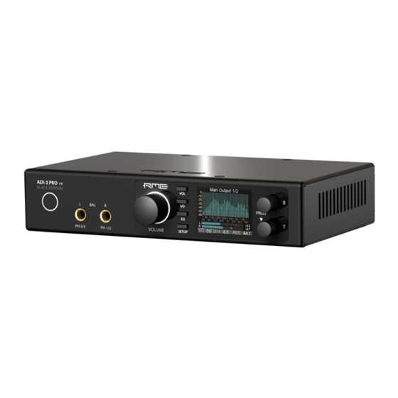
5. First Usage – Quick Start 5.1 Connectors and Controls The front of the ADI-2/4 Pro SE has 3 hi-precision rotary encoders with push function, 4 buttons, a standby power button, a high resolution IPS display, and two TRS headphone outputs plus one Pentaconn. -
Page 8: Quick Start
5.2 Quick Start Connect the unit to the included power supply and push the Standby button to start. The ADI-2/4 Pro SE ships with Basic Mode Auto activated (SETUP – Options – Device Mode / DSD – Basic Mode). The input selection for SPDIF (coaxial or optical), and the source selection for Phones Out 3/4 are also set to Auto, the SRC is activated for the SPDIF input. -
Page 9: Overview Menu Structure
The unit has several informative screens on the top level. These are Global Level Meters, Ana- lyzer Analog Input, Analyzer Line Output 1/2, Analyzer Phones Out 3/4, State Overview and Dark Volume. Change between them by pushing encoder 1 or 2 whenever any of them is dis- played. -
Page 10: Playback
5.5 Playback In the audio application being used, the ADI-2/4 Pro SE must be selected as output device. It can often be found in the Options, Preferences or Settings menus, as Playback Device, Audio De- vices, Audio etc. After selecting a device, audio data is sent to an analog or digital port, depending on which has been selected as playback device. -
Page 11: Power Supply
6. Power Supply In order to make operating the ADI-2/4 Pro SE as flexible as possible, the unit has a universal DC input socket, accepting voltages from 9.5 Volts up to 15 Volts. An internal switching regulator of the latest technology with high efficiency (> 90%) prevents internal hum noise by operating above audible frequencies. -
Page 12: Features Explained
8. Features Explained 8.1 Extreme Power Headphone Outputs During the development of the ADI-2 Pro an extensive research on today’s headphone amp tech- nology as well as headphones has been carried out. Many (many!) headphones later a maximum output level of +22 dBu (10 Volt) was set as development goal, as it will drive even insensitive headphones sufficiently, while a maximum output current of around 320 mA per channel will result in lots of power for lower impedance phones (2.1 Watts @ 32 Ohm). -
Page 13: Dual Phones Outputs
8.2 Dual Phones Outputs Many features and design decisions on the ADI-2/4 Pro SE come from personal usage and ex- perience. For example when comparing headphones: it turns out to be very difficult when having just one headphone output. Changing the phones on the head is already a disrupting process which hinders easy comparison, but without proper level adjustment first, and the need to unplug one and to plug the other, comparisons are only possible for coarse differences. -
Page 14: Bass / Treble
This is one of many major features not found on any similar device: a high-quality 5-band para- metric EQ, usable at up to 768 kHz sample rate, easy to set up and adjust, with a graphical display showing the resulting curve, and multiple storage places including individual naming. So whatever EQ setting you need, it is loaded and modified quickly. -
Page 15: Src (Sample Rate Conversion)
Here is an example on how it works: the user’s typical lowest level listening volume is at -35 dB at the unit. This value is now set by the user as Low Vol Ref in the Loudness menu. Then Bass and Treble Gain can be set between 0 and +10 dB. -
Page 16: Riaa Mode
Details on internal settings The Crossfeed effect is mainly defined by the filter frequency and the amount of crossfeed, here given as damping factor: 1: 650 Hz, -13.5 dB (just a touch) 2: 650 Hz, -9.5 dB (Jan Meier emulation) 3: 700 Hz, -6 dB (Chu Moy emulation) 4: 700 Hz, -4.5 dB (30°... -
Page 17: Dsp Limitations
8.8 DSP Limitations There is never enough DSP power – no matter how much you add (frustrated developer). That is true even for the ADI-2/4 Pro SE. Although being equipped with a quite capable 2.17 Giga FLOPS DSP chip, plus using the FPGA to perform further calculations (RME’s virtual DSP for mixing/routing, level meters, filtering, Crossfeed), 768 kHz sample rate takes its toll. - Page 18 User’s Guide ADI-2/4 Pro SE - v 1.0...
-
Page 19: Basic And Stand-Alone Operation Details
User’s Guide ADI-2/4 Pro SE Basic and Stand-Alone Operation Details User’s Guide ADI-2/4 Pro SE – v 1.0... -
Page 20: Rme Multi-Remote Control (Mrc)
9. RME Multi-Remote Control (MRC) The included infrared remote control, manufactured exclusively for RME, offers an almost com- plete remote control in a clear way. It is pre-set to control the ADI-2 DAC. Pressing a button therefore causes the SEL(ect) LED to light up green. To control the ADI-2/4 Pro SE code table 3 needs to be activated so that the SEL LED lights up in red color. -
Page 21: Other Remote Controls
9.2 Other Remote Controls The ADI-2/4 Pro SE can also be remotely controlled using third-party remote controls and custom IR transmitters. The well-known manufacturer Logitech has added the ADI-2/4 Pro SE to its re- mote control database. Others can use the codes documented here: http://www.rme-audio.de/downloads/adi24pro_ir_commands.zip Available are the original keys of the MRC and 52 Remap commands with direct access (without remapping). -
Page 22: Vol
Example: Press the key SETUP. The menu Setups is now shown. 1 within the circle on the right side indicates that by turning encoder 1 more pages are available. Turn encoder 1 left to enter Options. Now turn encoder 2 to scroll horizontally through all the subpages offered under Options: SPDIF / Remap Keys, Device Mode / DSD, Clock, Phones, Display. -
Page 23: Analog Input
12. I/O The I/O menu has all the settings for the analog stereo I/Os Analog Input, Line Output 1/2, Phones Output 1/2 and Phones Out 3/4. The submenu Parametric EQ mirrors the settings done in the graphical EQ screen. The submenus Bass/Treble and Loudness as well as some phase functions are only found on the two analog stereo outputs. -
Page 24: Parametric Eq
DC Filter RME (default), None. RME is a < 0.1 Hz filter in the FPGA with minimal phase error. In RIAA mode this filter is always active. For DSD recording DC filters are not available. 12.1.2 Parametric EQ Subpage Parametric EQ has the following entries: EQ Enable ON, OFF. - Page 25 Ref Level Sets the reference level for the analog outputs 1/2. Choices are +1 dBu, +7 dBu, +13 dBu, +19 dBu, +24 dBu, referenced to digital full scale level (0 dBFS). The RefLevel of the phones outputs are independently switchable to IEM (+1 dBu), Low Power (+7 dBu) and High Power (+19 dBu). Auto Ref Level ON, Off.
-
Page 26: Bass/Treble
Loopback OFF, Pre FX to 1/2 – 5/6, Post FX to 1/2 – 5/6, Post 1/2 – 5/6 -6 dB. Routes the current output signal to the corresponding USB record channels. For more details see chapter 17.4.3. Digital DC Protection ON, OFF, Filter. -
Page 27: Phones Output 1/2 And 3/4
12.3 Phones Output 1/2 and 3/4 Subpage Settings has the same settings as listed for Line Output 1/2, plus: Source Default: Auto. The source of the output Phones Out 3/4 can be chosen manually anytime. Available options are: Auto, AES, SPDIF, Analog, USB 1/2, USB 3/4. Auto here not only means current or available signal, but also channels 1/2. - Page 28 Notes The frequency graphics give a precise overview of the filter results. Overlapping filters influence each other. This can be used to achieve more than 12 dB gain, or to generate difficult frequency response optimizations. The ADI-2/4 Pro SE has an internal headroom of 24 dB. Extreme boosts with overlapping filters could cause an internal overload.
-
Page 29: Setup
Name Allows to edit the name of the current preset and to edit the name during the store process. Turn encoder 2 to select a let- ter, number or symbol, then press encoder 2 briefly to enter the next sign. After the last sign the cursor jumps to the field Store to. -
Page 30: Expert Settings
Optical Out Available settings are: SPDIF, ADAT. While the input adapts to the received signal automatically, the output needs to be switched manually. In Dig Thru mode with an ADAT signal received, the output is switched to ADAT automatically with all 8 input channels passed through. Remap Keys OFF, ON, Remote. -
Page 31: Clock
14.1.3 Device Mode / DSD Basic Mode Choices are Auto, AD/DA, USB, Preamp, Dig Thru and DAC. See chapter 17. CC-Mode Choices are Stereo and Multi-channel. The ADI-2/4 Pro SE supports two Class Compliant modes: 2 channel I/O, which allows to use sample rates up to 768 kHz even with iOS de- vices, and 6/8 channel mode to give access to all I/Os simul- taneously. -
Page 32: Display
Toggle Ph/Line OFF, 1/2, 3/4, 1/2+3/4, All Plugged, Line/Digital. Default: OFF. Activates the ability to toggle mute between Phones Out, rear Line Out and digital outputs. Pushing the VOLUME knob for half a second will then switch between loudspeakers connected to the rear and phones plugged into the front. -
Page 33: Load/Store All Settings
14.2 Load/Store all Settings This option allows to save the whole state of the unit as Setup in 9 memory slots. The EQ Presets are not included, they are stored separately and are available for any setup. The current state of the EQ is also stored, and written to the EQ memory slot Manual during load of a Setup. -
Page 34: Top Screens
15. Top Screens The ADI-2/4 Pro SE has four different meter screens: a global level meter that shows all signal levels of all I/Os simultaneously, an Analyzer showing the audio signal content on the analog inputs and both analog outputs 1/2 and 3/4, a state overview showing the digital states of AES, SPDIF and USB, and a dark Volume screen with comprehensive information. -
Page 35: State Overview
The most important application using a Spectral Analyzer is the visualization of frequencies and levels found in music or speech. The Analyzer shows levels and frequencies even at the edge of the human ear's abilities – or that of the used speakers and headphone. The visual display helps to train ones ears, makes coarse errors visible, and shows what sometimes might stay unnoticed. -
Page 36: Dark Volume
But SPDIF and AES can also transport AC-3 and DTS encoded surround sound. This signal sounds like chopped noise at full volume. Therefore the ADI-2/4 Pro SE receiver circuit checks the Non-Audio flag within the Channel Status. If found the signal is already muted directly in the receiver. -
Page 37: Warning Messages
16. Warning Messages The ADI-2/4 Pro SE will show different warning messages and provide guidance in certain cases. Hi-Power Mode Active When Hi-Power mode is active with the Volume set higher than -15 dB and a phone is plugged in, this message reminds the user to check the current volume setting, and to make sure the used headphone will stand the high output power without get- ting destroyed. - Page 38 DC detected (Digital) This warning message appears when the digital source signal has too high DC component and the current VOLUME setting exceeds a certain value. The digital DC detection protects all analog outputs from faulty digital signals. They will be discon- nected (relais) until the DC in the source signal has been re- duced or eliminated.
-
Page 39: Modes
17. Modes 17.1 Auto The ADI-2/4 Pro SE is an AD/DA converter, USB audio interface, USB DAC, analog headphone amp, format converter and digital monitoring device, with extended flexibility and versatility, equipped with 5 input sources and 8 output paths. Usually that means an overflowing menu struc- ture and endless searches in the menus to get it working in even simple applications. -
Page 40: Preamp
17.2 Preamp Preamp: Analog in to Analog out (internal digital routing). This mode can be activated manually by selecting Basic Mode – Preamp. The device enters Preamp mode automatically when Basic Mode is set to Auto and no digital input signal and no USB is detected. -
Page 41: Ad/Da Converter
17.3 AD/DA Converter AD/DA: Converter Mode, analog in to all digital outs, digital in to all analog outs. This mode can be activated manually by selecting Basic Mode – AD/DA. The device enters AD/DA mode automatically when Basic Mode is set to Auto and a digital input signal is detected. The detected digital input signal will also become the signal source. -
Page 42: Usb
17.4 USB USB: interface mode. This mode can be activated manually by selecting Basic Mode – USB. The device enters USB mode automatically when Basic Mode is set to Auto and a USB connection is detected. USB has priority over AD/DA mode. In USB mode all inputs are routed to USB, all outputs are fed from USB. -
Page 43: Multichannel Mode
17.4.2 Class Compliant Multi-channel mode With USB connected all digital and analog inputs (6 channels) are routed to USB recording. In the same way USB playback will feed all outputs separately (8 channels). In 6/8 channel mode all I/Os can be used separately. Phones output 3/4 provides USB playback of channels 1/2 when its Source is set to Auto (default). -
Page 44: Loopback Analog Out To Usb Record
17.4.3 Loopback Analog Out to USB Record Loopback is an optional internal routing of the analog outputs 1/2 and 3/4 to USB Record 1/2, 3/4 and 5/6. This can be used to send playback data to DIGICheck Mac, process and re-record audio and much more. -
Page 45: Digital Through
17.5 Digital Through Mode This additional mode is a manual option only, it is not available via Basic Mode Auto. It has to be activated manually by selecting Basic Mode – Dig Thru. The purpose of the Digital Through Monitor is exactly what its name describes. A single digital input signal is passed through the unit and can be monitored on the analog outputs at the same time. -
Page 46: Dac
17.6 DAC This additional mode is a manual option and not available via Basic Mode Auto. It must be acti- vated manually by choosing Basic Mode – DAC. DAC simplifies operation and source selection when the ADI-2/4 Pro SE is used like a typical HiFi DAC: ... -
Page 47: Balanced Phones Mode
18. Balanced Phones Mode In balanced operation, two identical power amplifiers are used to drive one side of the phones each. Compared to normal, grounded operation, the voltage seen by the phone driver/speaker is doubled. The power sent to it is even quadrupled. With the comparatively low power required by headphones, and its already powerful Extreme Power outputs, the balanced phones mode of the ADI-2/4 Pro SE has not been optimized for more power, but more fidelity. -
Page 48: General
19. DSD 19.1 General DSD (Direct Stream Digital) is a stream with single bit resolution, but multiple times the sample rate of the CD. DSD64 equals 64 times 44.1 kHz = 2.8 MHz, DSD128 5.6 MHz, DSD256 11.2 MHz. Versions with multiples of 48 kHz also exist, up to 12.2 MHz. To transfer DSD data over SPDIF, AES or even USB, DSD over PCM (DoP) is the de-facto stand- ard. -
Page 49: Dsd Record
19.3 DSD Record The ADI-2/4 Pro SE converts the analog input data not only to PCM, but optionally also to DSD. Via I/O - Analog Input - AD Conversion the AD-converter can be switched from PCM (Default) to DSD. Based on the current mode the DSD data are then sent to the outputs AES and SPDIF (DoP), USB (DoP via ASIO or ASIO native), and the analog outputs 1/2 and 3/4 (re-converted by the DAC). -
Page 50: Beyond
19.5 Beyond… The ADI-2/4 Pro SE enables configurations, settings and applications that might give answers to a lot of questions. Is there really a sonic difference between different DA-filters with different im- pulse response properties? Just try it! Does an AD/DA converter chain sound different with differ- ent sample rates? Just try it! Does the same converter chain sound different - and how does it sound at all - if one uses DSD? Just try it! User’s Guide ADI-2/4 Pro SE - v 1.0... -
Page 51: Inputs And Outputs
User's Guide ADI-2/4 Pro SE Inputs and Outputs User’s Guide ADI-2/4 Pro SE – v 1.0... -
Page 52: Analog Inputs
20. Analog Inputs The ADI-2/4 Pro SE has two analog line inputs that can operate with levels up to +24 dBu. The electronic input stage uses a servo balanced design which handles unbalanced (TS jacks) and balanced signals (TRS / XLR) correctly, automatically adjusting the level reference. When using unbalanced cables with the XLR inputs, pin 3 of the XLR jack should be con- nected to ground. -
Page 53: Line Out Trs 1/2
21.2 Line Out TRS 1/2 The ADI-2/4 Pro SE has two impedance balanced, short-circuit protected analog Line outputs that can operate with levels up to +21.5 dBu (Ref Lev +19 dBu with Volume set to +2.5 dB). Using a stereo (TRS) jack the output uses two 100 Ohm resistors internally to achieve impedance balanc- ing. -
Page 54: Ph Out 3/4
If operation of the phones output 1/2 is desired, the Dual Phones mode has to be switched on. The menu has the additional option to turn off the rear outputs as soon as PH 1/2 is plugged in. Default is Mute On when plugged. While these outputs are praised as ideal head- phone outputs, eventually as well as technically they also are ideal line outputs. -
Page 55: Digital Connections
22. Digital Connections 22.1 AES The ADI-2/4 Pro SE provides one XLR AES/EBU input and output each via the included breakout cable when connected to the D-sub 9 pin socket on the back of the unit. Connection is accom- plished using balanced cables with XLR plugs. Input and Output are transformer-balanced and ground-free. -
Page 56: Adat
To receive signals in AES/EBU format on the coaxial input, an adapter cable can be used. Pins 2 and 3 of a female XLR plug are connected individually to the two pins of a phono plug. The cable shielding is only con- nected to pin 1 of the XLR - not to the phono plug. -
Page 57: Installation And Operation - Windows
User's Guide ADI-2/4 Pro SE Installation and Operation – Windows User’s Guide ADI-2/4 Pro SE – v 1.0... -
Page 58: Driver Installation
23. Driver Installation Note: When operated in CC mode Stereo the ADI-2/4 Pro SE is fully compatible to Windows 10 (1709 or newer). An installation of RME drivers is still recommended. They add ASIO (PCM, DSD DoP and DSD Native) and 768 kHz WDM. They are also required for firmware updates and DIGICheck. -
Page 59: Configuring The Adi-2/4 Pro Se
24. Configuring the ADI-2/4 Pro SE 24.1 Settings Dialog Configuration of the ADI-2/4 Pro SE is usually done directly at the unit. For ASIO operation sample rate and buffer size (latency) can be set via a dedicated settings dialog. The panel 'Settings' can be opened by clicking on the fire symbol in the Task Bar's notification area Any changes made in the Settings dialog are applied immediately - con- firmation (e.g. -
Page 60: Clock Modes - Synchronization
24.2 Clock Modes - Synchronization In the digital world, all devices must be either Master (clock source) or Slave (clock receiver). Whenever several devices are linked within a system, there must always be a single master clock. A digital system can only have one master! If the ADI-2/4 Pro SE’s clock mode is set to 'In- ternal', all other devices must be set to ‘Slave’. -
Page 61: Dvd-Playback (Ac-3/Dts)
Loudspeaker in the Sound panel. 25.3 Multi-client Operation RME audio interfaces support multi-client operation. Several programs can be used at the same time. The formats ASIO and WDM can even be used on the same playback channels simultane- ously. -
Page 62: Asio
25.5 ASIO Start the ASIO software and select ASIO MADIface USB as the audio I/O device or the audio driver. The sample rate is set by the ASIO application. The buffer size (latency) is set in the RME Settings dialog. The number of available channels depends on the current Class Compliant mode: 2 channels I/O when set to Stereo, 6 in / 8 out when set to Multi-channel. -
Page 63: Installation And Operation - Mac Os X
User's Guide ADI-2/4 Pro SE Installation and Operation – Mac OS X User’s Guide ADI-2/4 Pro SE – v 1.0... -
Page 64: General
27. General The ADI-2/4 Pro SE is a UAC 2.0 Class Compliant device. Mac OS X has full UAC support built- in, there is no driver installation required. Connect computer and ADI-2/4 Pro SE with a USB cable. Mac OS X detects the new hardware as ADI-2/4 Pro SE (serial number). The number of available channels depends on the current Class Compliant mode: 2 channels I/O when set to Stereo, 6 in / 8 out when set to Multi-channel. -
Page 65: Clock Modes - Synchronization
27.2 Clock Modes - Synchronization In the digital world, all devices must be either Master (clock source) or Slave (clock receiver). Whenever several devices are linked within a system, there must always be a single master clock. A digital system can only have one master! If the ADI-2/4 Pro SE’s clock mode is set to 'In- ternal', all other devices must be set to ‘Slave’. - Page 66 User’s Guide ADI-2/4 Pro SE - v 1.0...
-
Page 67: Installation And Operation - Ios
User's Guide ADI-2/4 Pro SE Installation and Operation – iOS User’s Guide ADI-2/4 Pro SE – v 1.0... -
Page 68: General
29. General The ADI-2/4 Pro SE operates in Class Compliant mode (UAC 2.0), a standard that is natively supported by operating systems like iOS, Mac OS X, Linux and Windows 10 (since 1709). No proprietary drivers are required, the device will be directly recognized. The ADI-2/4 Pro SE provides iOS devices with the professional analog I/O connections they lack. -
Page 69: Technical Reference
User's Guide ADI-2/4 Pro SE Technical Reference User’s Guide ADI-2/4 Pro SE – v 1.0... -
Page 70: Technical Specifications
33. Technical Specifications 33.1 Analog Inputs XLR/TRS Input: XLR and 6.3 mm TRS jack, servo-balanced Input impedance @ 1 kHz, balanced: 90 kOhm, unbalanced: 45 kOhm Input sensitivity switchable +24 dBu, +19 dBu, +13 dBu, +7 dBu, +1 dBu @ 0 dBFS ... -
Page 71: Digital Inputs
THD @ 0 dBFS: < -120 dB, 0.0001 % THD+N @ 0 dBFS: -116 dB, 0.00016 % Channel separation: > 130 dB Output impedance @ 1 kHz @ +24/+19/+13 dBu: 213 Ohm Output impedance @ 1 kHz @ +7/+1 dBu: 113 Ohm 1/2 TRS (rear) As 1/2 XLR, but: ... -
Page 72: Digital Outputs
AES/EBU 1 x XLR, transformer-balanced, galvanically isolated, according to AES3-1992 Input sensitivity 1.0 Vpp SPDIF coaxial 1 x RCA, transformer-balanced, according to IEC 60958 High-sensitivity input stage (< 0.3 Vpp) AES/EBU compatible (AES3-1992) SPDIF optical ... -
Page 73: Connector Pinouts
33.7 Connector Pinouts Pin assignment of the 9-pin D-sub connector, breakout cable SPDIF / AES Note: The digital breakout cable is identical to the one used in HDSPe series cards. Name Name Name AES Out + SPDIF In - SPDIF Out + AES In + AES Out - SPDIF In +... -
Page 74: Technical Background
34. Technical Background 34.1 Lock and SyncCheck In the analog domain one can connect any device to another device, a synchronization is not necessary. Digital audio is different. It uses a clock base. The signal can only be processed and transmitted when all participating devices share the same clock. -
Page 75: Latency And Monitoring
Under Windows RME provides the MADIface series driver to use the ADI-2/4 Pro SE like any other RME audio interface, with the same spectacular performance, although being a Class Com- pliant device. Both WDM and ASIO are available. Latency under ASIO mainly depends on the buffer size set in the driver’s Settings dialog. -
Page 76: Usb Audio (Windows)
34.3 USB Audio An ADI-2/4 Pro SE can achieve a performance similar to a PCI or PCI Express based soundcard when used with an optimal PC. Low CPU load and click-free operation even at 64 samples buffer size are indeed possible on current computers. However, using older computers a simple stereo playback will begin to cause a CPU load of more than 30%. -
Page 77: M/S-Processing
Now it should be clear why the above advice can be quite important even for an ADI-2/4 Pro SE. In Multi-channel mode the numbers are even higher: Base 48 kHz 96 kHz 192 kHz/DSD64 384 kHz/DSD128 768 kHz/DSD256 Channels Although on the edge, 384 kHz would work. But 768 kHz - no way. As the ADI-2/4 Pro SE should work under iOS as well, which has a system limit in transfer bandwidth, its USB transfer mode is limited to 192 kHz in Multi-channel mode. -
Page 78: Emphasis
34.5 Emphasis In the early times of digital audio, with AD and DA converters of only 14 bit resolution, a technique was used that is also known from radio transmission: pre- and de-emphasis. The audio signal is equalized to have treble boosted before the conversion. When played back an analog treble filter (the term high cut seems a bit strong) is required. -
Page 79: True Balanced Phones Mode
34.6 True Balanced Phones Mode Headphones usually share one wire between left and right channel: the common ground, hence operation is unbalanced. A different way to build a powerful output stage uses a balanced design. Both wires to the speaker are ‘phase’, there is no ground connection. This technique is mostly used in car audio, as the operating voltage is limited to 12 Volt, and balanced operation, here called bridging, delivers double the output voltage and four times the output power to the speaker. - Page 80 This design, as common as it is, has several disadvantages: an analog inverter stage has to be added to the signal path the common mode situation of the signal at the phones is compromised by the difference between + and – phase, caused by the analog inverter ...
-
Page 81: Crosstalk At The Trs Phones Outputs
The whole signal path from DAC to the headphone speaker is balanced (!) Signal inversion happens fully transparent and lossless within the digital domain Signal inversion is completely transparent and lossless The entire signal path from the DAC to the headphones is balanced ... - Page 82 But how relevant are these 'low' values anyway? At what point do you actually hear crosstalk? LPs only manage 25 dB and subjectively already offer full stereo, FM radio is at 30 to 35 dB. Fortunately, the ADI allows you to try this out for yourself! ...
-
Page 83: Steadyclock Fs
34.8 SteadyClock FS RME’s SteadyClock technology guarantees an excellent performance in all clock modes. Its highly efficient jitter suppression refreshes and cleans up any clock signal. Thanks to the efficient jitter suppression, the AD- and DA-conversion always operates on highest sonic level, being com- pletely independent from the quality of the incoming clock signal. -
Page 84: Adi-2/4 Pro Se As Measurement Frontend
34.9 ADI-2/4 Pro SE as Hardware I/O for Measurements Audio measurement systems have been (and still are) quite expensive. Several years ago much cheaper software based solutions started to replace the expensive references, whenever the measurements did not require absolute accuracy. Although the software itself might be 100% accurate, the hardware used as generator and analyzer is often just a consumer soundcard. - Page 85 DC and detection of very low frequencies Audio AD-converters always have a DC filter, because the ADCs operate with a fixed bias voltage (VCOM), and any deviation from this leads to a degradation of their performance. An externally supplied DC voltage would do exactly that. In all Pro, two unipolar Nichicon audio electrolytic capacitors, directly at the input jack, prevent external DC voltage from entering.
-
Page 86: Noise Level In Hi-Speed Modes
34.10 Noise Levels in Hi-Speed Modes The outstanding signal to noise ratio of the ADI-2/4 Pro SE AD-converters can be verified even without expensive test equipment, by using record level meters of various software. But when activating higher sample rates, the displayed noise level will rise from about -121 dBFS to -118 dBFS at 96 kHz, and –115 dBFS at 192 kHz, etc. -
Page 87: Ad Impulse Responses
34.11 AD Impulse Responses On the AD side the ADI-2/4 Pro SE offers four oversampling filters, shown to the right from top to bottom: Short Delay Sharp, Short Delay Slow, Sharp and Slow. Basi- cally these behave and operate exactly the same way as the DAC filters described in the next chapter. -
Page 88: Impulse Responses
SD Slow and Slow work best at 88.2 and up, because the decrease in the high frequency area then happens outside the audible range. At the same time the impulse response is near perfect – caused by both the filter as well as the doubled sample rate. Note: At 705.6 and 768 kHz sample rate the filter selection is not available. - Page 89 Brickwall All the above filters intentionally violate a rule of digital technology - at half the sample rate the filter should already have maximum stop- band attenuation, i.e. at 44.1 kHz sample rate at an audio frequency of 22.05 kHz. But in practice there are no disadvantages with a slightly higher filter (24 kHz).
-
Page 90: Frequency Response Preamp Mode (Ad/Da)
34.13 Frequency Response Preamp Mode (AD/DA) Note: 44.1 kHz to 192 kHz measured with filter Sharp on AD and DA. 34.14 AD Frequency Response and Filter Curves User’s Guide ADI-2/4 Pro SE - v 1.0... -
Page 91: Filter Curves @ 44.1 Khz
34.15 DA Filter Curves @ 44.1 kHz Note: Sharp/SD Sharp and Slow/SD Slow are very similar, but not fully identical. NOS shows a very early drop. SD Low Dispersion shows a somewhat early treble drop, but also a very good stopband attenuation, see next measurement. -
Page 92: Loudness
34.16 Loudness 34.17 Bass / Treble User’s Guide ADI-2/4 Pro SE - v 1.0... -
Page 93: Distortion Measurements Analog I/O
34.18 Distortion Measurements Analog I/O The following measurements show spectral analysis of the AD and DA conversion of the ADI-2/4 Pro SE, which includes the analog input and output stages. While the noise and modulation be- havior is identical for all devices, the AD and DA chips used have tolerances in the height and distribution of the harmonics. - Page 94 Output Phones TRS +20 dBu output level @ 32 Ohm equal 1.9 W (per channel) Crosstalk Phones Balanced / Unbalanced From top to bottom (all 32 Ohm load): TRS extension cord 3 meter (9.8 ft). TRS Phones Out 1/2 and 3/4. Phones Balanced mode using 2 x TRS Out or Pentaconn. No load: XLR Out 1/2. User’s Guide ADI-2/4 Pro SE - v 1.0...
- Page 95 34.19 Extreme Power Charts Note: Since the maximum undistorted output level is reached at VOLUME +2.5 dB, the Hi-Power measurements (unbalanced and balanced) were taken at this setting. Low Power and IEM were measured at VOLUME 0 dB. User’s Guide ADI-2/4 Pro SE – v 1.0...
-
Page 96: Extreme Power Charts
34.20 Phones Distortion Comparison The Extreme Power output stage remains virtually distortion-free under load until the maximum level is reached (clipping), which leads to an increasingly lower THD+N as the level increases. This is not the case with many other headphone amplifiers. So much for our marketing department. - Page 97 User’s Guide ADI-2/4 Pro SE – v 1.0...
-
Page 98: Impedance Based Level Meters Ph 1-4
34.22 Impedance based Level Meters PH 1-4 The horizontal level meters in various screens of outputs 1 to 4 show the digital level fed to the DAC. With loads higher than 32 Ohms the level meter's display matches the real analog output level (0 dBFS = +19 dBu). -
Page 99: Digital Volume Control
34.23 Digital Volume Control The ADI-2/4 Pro SE deliberately avoids an analog level adjustment by means of a potentiometer. Its digital level control in TotalMix technology surpasses an analog one in practically every con- ceivable point. Typical disadvantages of setting with potentiometers: ... - Page 100 The following measurement shows a digital full-scale sine of 1 kHz, 16 bits without dither, which is reduced in level by 40 dB. Also shown are a full-scale sine of 1 kHz with 24 bit, at 60 dB and 93.8 dB level attenuation, which is the lowest volume setting the ADI-2/4 Pro SE offers. A high-resolution FFT makes it possible to disassemble the signal into individual frequencies, and to identify unwanted components down to a level of -190 dBFS.
-
Page 101: Bit Test
34.24 Bit Test A bit test is used to check the playback path for unwanted changes in the playback data. Playback software can cut bits, add dither, or change the level - without these changes becoming noticed easily. A poorly programmed driver can manipulate bits, and a playback hardware could be both badly designed and defective (hanging bits, swapped bits). -
Page 102: Digital Dc Protection
34.25 Digital DC Protection A protective circuit that detects DC voltage at the output of an amplifier, and cuts off the speakers if it is too high, is standard in power amplifiers. DC voltage not only means that the speaker's diaphragm does not remain in the ideal center position (instead it is permanently stuck out or retracted), but also that the speaker is subjected to a larger, constant current flow. - Page 103 In the digital domain, the threshold of detection lies between -31 dBFS and -16.5 dBFS, depend- ing on the volume setting, reference level and respective hardware output. DC affected sources If you just want to listen to music, you expect (and rightly so) that it does not contain inaudible signal components that can cause effects ranging from slight distortion to destruction.
-
Page 104: Operation In The Hi-Fi Environment
34.26 Operation in the Hi-Fi Environment The ADI-2/4 Pro SE is a gem not only with professional applications but also when using it at home with the stereo system. While users working in the studio environment know everything about reference levels and all kinds of connectors, others get confused by the missing RCA sock- ets and have doubts that the unit can be used with Hi-Fi at all - and how to connect it then. - Page 105 How do I connect the device to my other devices that have only RCA? By a simple adapter mono 6.35 mm to RCA (also called Phono and Cinch). The adapters are plugged into the rear inputs and outputs - done. Now the existing RCA cables can be used with the ADI-2/4 Pro SE.
- Page 106 Doesn't such a low level cause a significant increase in noise? Usually yes - but not with the ADI-2/4 Pro SE. Switching the reference levels is done in the analog domain, in hardware. The circuit has been optimized for near maximum signal to noise ratio even at +1 dBu.
- Page 107 First, the current state is stored as Setup 1 during USB playback: Press the SETUP key, turn encoder 1 (menu Setups appears), turn encoder 2 until the field Setup Select shows the choice Store 1. Now press encoder 2 until the cursor has jumped down to the lowest field and the setup has been saved (or alternatively enter a different name in-between - but this can also be done later).
-
Page 108: Using A Turntable
34.27 Using a Turntable The ADI-2/4 Pro SE is directly compatible to turntables with MM cartridge (Moving Magnet). See also chapter 8.8. Thus it allows digitizing the precious vinyl discs in highest quality. Connection To connect a turntable to the two combo XLR/TRS jacks, two RCA to TS adapters are required, see also photo on page 105. - Page 109 In this regard it is very helpful that the ADI-2/4 Pro's level meter reacts to every single sample. When recording at 192 kHz, pops up to 96 kHz are detected, which thus only need to be about 11 µs long to become visible. But in practice nothing happens, and you can be sure: where you see nothing, there is nothing.
-
Page 110: Block Diagram
34.28 Block Diagram User’s Guide ADI-2/4 Pro SE - v 1.0... - Page 111 User's Guide ADI-2/4 Pro SE Miscellaneous User’s Guide ADI-2/4 Pro SE – v 1.0...
-
Page 112: Accessories
35. Accessories There are several items available for the ADI-2/4 Pro SE: Part Number Description NT-ADI24ProSE Power supply for ADI-2/4 Pro SE. Robust and light-weight switching power supply, 100 V-240 V AC, 12 V 3.3 A DC. Lockable DC connector. BO968 Digital breakout cable (9-pin D-sub to 2 x XLR and 2 x RCA) RME USB 2 cable, length 78”... -
Page 113: Appendix
37. Appendix RME news, driver updates and further product information are available on RME’s website: https://www.rme-audio.com Worldwide distribution: Audio AG, Am Pfanderling 60, D-85778 Haimhausen, Tel.: (49) 08133 / 918170 Support via e-mail: support@rme-audio.com List of international supporters: https://www.rme-audio.de/support.html RME user forum: https://forum.rme-audio.de Acknowledgements The Bauer Binaural Crossfeed effect in the ADI-2/4 Pro SE was inspired by Boris Mikhaylov’s... -
Page 114: Declaration Of Conformity
38. Declaration of Conformity This device has been tested and found to comply with the limits of the European Council Directive on the approximation of the laws of the member states relating to electromagnetic compatibility according to RL2014/30/EU, and European Low Voltage Directive RL2014/35/EU. This device complies with Part 15 of the FCC Rules.
Need help?
Do you have a question about the ADI-2 Pro SE and is the answer not in the manual?
Questions and answers