Table of Contents
Advertisement
User's Guide
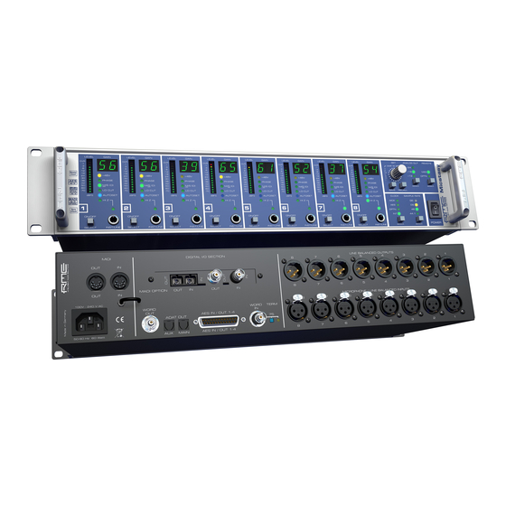
Micstasy
The Professional's Full Range Solution
™
™
TotalGain
I64 Option Slot
™
™
™
SteadyClock
SyncCheck
AutoSet
Professional Mic/Line/Instrument Preamp and AD-Converter
8-Channel Microphone / Line Preamp with Line Outputs
8-Channel Analog to AES / ADAT Interface
Optional 64-Channel MADI Interface
24 Bit / 192 kHz Digital Audio
MIDI Remote Control
AES-3
AES-10
24 Bit Interface
Advertisement
Table of Contents

Related Manuals for RME Audio Micstasy


Summary of Contents for RME Audio Micstasy
- Page 1 User’s Guide Micstasy The Professional’s Full Range Solution ™ ™ TotalGain I64 Option Slot ™ ™ ™ SteadyClock SyncCheck AutoSet Professional Mic/Line/Instrument Preamp and AD-Converter 8-Channel Microphone / Line Preamp with Line Outputs 8-Channel Analog to AES / ADAT Interface Optional 64-Channel MADI Interface 24 Bit / 192 kHz Digital Audio MIDI Remote Control...
-
Page 2: Table Of Contents
11.10 Pro Tools MIDI Compatibility (pt) ......23 11.11 Digital Output (do) ..........23 11.12 Word Clock Out (Co)..........23 11.13 Display Auto Dark (dArk) ........24 11.14 Oscillator (oSC)............24 Remote Control 12.1 MIDI..............25 12.2 MIDI over MADI............25 12.3 Remote Control Software........26 User’s Guide Micstasy © RME... - Page 3 18.10 SteadyClock............54 Block Diagram............55 MIDI Implementation Micstasy 20.1 Basic SysEx Format ..........56 20.2 Message Types ........... 56 20.3 Table ..............57 20.4 Pro Tools MIDI Compatibility ....... 59 20.5 Yamaha MIDI Compatibility ......... 60 User’s Guide Micstasy © RME...
-
Page 4: Important Safety Instructions
When mounting in a rack, leave some space between this device and others for ventilation. Unauthorized servicing/repair voids warranty. Only use accessories specified by the manufacturer. Read the manual completely. It includes all information necessary to use and operate this device. User’s Guide Micstasy © RME... -
Page 5: General
User’s Guide Micstasy General User’s Guide Micstasy © RME... -
Page 6: Introduction
Although the Micstasy breaks into a price category which is quite unusual for an RME product, it still offers the typical, outstanding price/performance ratio known from RME. Micstasy's features will excite you – but even more the performance and smartness that it shows in solving any given task. -
Page 7: First Usage - Quick Start
After pressing the RECALL button, selecting a preset with the rotary encoder and pressing RECALL a second time, the selected preset is loaded and the state of the channels is updated. In the CLOCK SECTION the current clock reference and frequency multiplier is chosen. User’s Guide Micstasy © RME... - Page 8 Micstasy operate in the range of 100V to 240V AC. It is short- circuit-proof, has an integrated line-filter, is fully regulated against voltage fluctuations, and sup- presses mains interference. With installed I64 MADI Card: MADI I/O optical: Standard MADI ports. MADI I/O koaxial (BNC): Standard MADI ports. User’s Guide Micstasy © RME...
-
Page 9: Quick Start
The storing process is triggered 4 seconds after the last change, and is signalled in the Gain display as quickly moving point. 5. Accessories RME offers several optional components for the Micstasy: Part Number Description OK0050 Optical cable, Toslink, 0.5 m (1.7 ft) -
Page 10: Warranty
All entries in this User's Guide have been thoroughly checked, however no guarantee for cor- rectness can be given. RME cannot be held responsible for any misleading or incorrect informa- tion provided throughout this manual. Lending or copying any part or the complete manual or its contents as well as the software belonging to it is only possible with the written permission from RME. - Page 11 For this the device has to be sent free to the door to: IMM Elektronik GmbH Leipziger Straße 32 D-09648 Mittweida Germany Shipments not prepaid will be rejected and returned on the original sender's costs. User’s Guide Micstasy © RME...
- Page 12 User’s Guide Micstasy © RME...
-
Page 13: Usage And Operation
User’s Guide Micstasy Usage and Operation User’s Guide Micstasy © RME... -
Page 14: Front Panel Controls
* The factory default order when stepping through the functions is as described. Hold Select button 8 pressed from power-on until the Gain displays show up to change the order of Hi Z and I. The factory default mode is set by holding Select button 7 on power-up. User’s Guide Micstasy © RME... -
Page 15: Clock Section
AD-converters, thus matching the front panel level meters level indication. Reference 0 dBFS @ Analog Headroom +24 dBu 3 dB +19 dBu 8 dB +13 dBu 14 dB User’s Guide Micstasy © RME... -
Page 16: Remote
Micstasy. The phantom power of the Micstasy is short-circuit proof. With a maximum load on all eight channels the internal voltage from the power supply does not drop below 47 Volts. User’s Guide Micstasy © RME... -
Page 17: Phase
0.03 %. Thus the sum of all generated harmonics is 69 dB below the fundamental, which is again already lowered by 22 dB – and is therefore without any meaning. User’s Guide Micstasy © RME... -
Page 18: Autoset
The front input INST/LINE has an input impedance of 5.6 kOhm. Connecting passive instru- ments like bass and guitar, an activation of HI Z changes the input impedance to 470 kOhm, providing perfect conditions for these types of signal sources. User’s Guide Micstasy © RME... -
Page 19: Instrument / Line
Save and Recall by pushing these buttons, ANY setup process can be exited immediately by a quick double-push on either Save or Recall. Also it is not necessary to wait 6 seconds until the flashing stops or the setup menu is exited automatically – just do the double-push. User’s Guide Micstasy © RME... -
Page 20: The Setup Menu
In Double Speed the delay is 18, in Quad Speed 12 samples. The in most cases slightly increased delay is outweighed by the big advan- tage of sample-aligned I/Os when using multiple units. User’s Guide Micstasy © RME... -
Page 21: Id (Id)
As soon as the current value is met, AutoSet starts to reduce the Gain. This way a headroom equalling the threshold value is created, because the level can not be higher than the current value. User’s Guide Micstasy © RME... -
Page 22: Follow Clock (Fc)
AutoSet will light up. The only way to determine whether channels are linked or not is to open the Setup menu. Even when Downlink is activated, the values determined by AutoSet can be changed manually without changing relative levels. To do so, all linked channels must be selected when changing gain. User’s Guide Micstasy © RME... -
Page 23: Pro Tools Midi Compatibility (Pt)
S/MUX method the device else can not know which of the incoming 2 (DS) or 4 (QS) word clock edges is the right one. * With the Micstasy this limitation is also valid for the AES output, as the device internally handles all the data streams in S/MUX mode. User’s Guide Micstasy © RME... -
Page 24: Display Auto Dark (Dark)
With activated test tone the numerical display of the corresponding channel will show ‘to’ (test oscillator) instead of the Gain value. Note: oSC is available since firmware version 2.1. User’s Guide Micstasy © RME... -
Page 25: Remote Control
But what about MIDI? Be it remote control commands or sequencer data, in practice only a single MADI line will not suffice. Daher entwickelte RME die MIDI over MADI Technolo- gie. The data at the MIDI input are being included into the MADI signal invisibly, and can be collected at the MIDI output of another Micstasy, ADI-6432, ADI-642, ADI-648, ADI-8 QS or a HDSP MADI, at the other end of the MADI line. -
Page 26: Remote Control Software
MADI to the Micstasy. 12.3 Remote Control Software A free remote software for Windows and Mac OS X can be downloaded from the RME website. It can use any existing MIDI port within the system to perform remote control and status re- quests of any number of Micstasy via a simple mouse click. - Page 27 MADI Bridge. The following settings are not supported under MIDI, therefore can not be set using MIDI Remote: - The order of the functions (Select key 7/8) - Pro Tools MIDI compatibility On/Off (Setup menu) User’s Guide Micstasy © RME...
- Page 28 User’s Guide Micstasy © RME...
-
Page 29: Inputs And Outputs
User’s Guide Micstasy Inputs and Outputs User’s Guide Micstasy © RME... -
Page 30: Analog Inputs / Outputs
When using unbalanced cables with TRS jacks: be sure to connect the 'ring' contact of the TRS jack to ground. Otherwise noise may occur, caused by the unconnected negative input of the balanced input User’s Guide Micstasy © RME... -
Page 31: Line Out
– distortion, frequency response and signal to noise ratio do not change, or rather exactly like the analog overall gain. Set to +13 dBu and +19 dBu the Micstasy is fully compatible to all RME devices having +4 dBu and Lo Gain as input reference. -
Page 32: Digital Outputs
2 channels per AES wire. The effective sample frequency equals the clock on the AES wire. In case a conversion from/to Single, Double and Quad Wire is required, the RME ADI-192 DD, an 8-channel universal sample rate and format converter, is highly recommended. -
Page 33: Adat Optical
ADAT outputs is only half the frequency of the AES outputs. As interesting as this is – you don't need to think about it. 96 kHz capable ADAT hardware, like all current RME digital interfaces, re-combine the data automatically. The user (and the DAW software) does not see any split data, but just single channels at the expected double sample rate. -
Page 34: I64 Madi Card
The problem of this offset is solved by the function Delay Compensation, see chapter 11.3. It delays the signals in a way that they are sample-synchronous in multi-device operation. The diagram on the next page shows a serial setup with HDSP MADI card, three Micstasy and acti- vated Delay Compensation. User’s Guide Micstasy © RME... -
Page 35: Differences Micstasy / Adi-642
ID, and with this the according channel routing. Mixed setups: Auto ID and Auto are compatible. In contrast (A)DC is automatic only with the 642. The Micstasys require to activate Delay Compensation manually in each unit. User’s Guide Micstasy © RME... -
Page 36: Word Clock
As soon as a valid signal is detected, the WCK LED is constantly lit, oth- erwise it is flashing. Thanks to RME's Signal Adaptation Circuit, the word clock input still works correctly even with heavily mis-shaped, dc-prone, too small or overshoot-prone signals. Thanks to automatic signal centering, 300 mV (0.3V) input level is sufficient in principle. -
Page 37: Technical Description And Background
22 MHz from a slow word clock of 44.1 kHz is no problem anymore. Additionally, jitter on the input signal is highly rejected, so that even in real world usage the re-gained clock signal is of highest quality. User’s Guide Micstasy © RME... -
Page 38: Cables And Termination
DIN jack each. The MIDI I/O is used for: • remote control of the Micstasy, see chapter 12.1 • transmission of MIDI data and remote control commands over MADI, in case the optional I64 MADI Card has been fitted, see chapter 12.2. User’s Guide Micstasy © RME... -
Page 39: Technical Reference
User’s Guide Micstasy Technical Reference User’s Guide Micstasy © RME... -
Page 40: Technical Specifications
• Maximum input level, Gain 50 dB: -29 dBu Line Out 1-8, rear • Maximum output level: +27 dBu • Output: XLR, balanced • Output impedance: 150 Ohm • Output level switchable +13 dBu, +19 dBu, +24 dBu User’s Guide Micstasy © RME... -
Page 41: Digital Inputs
• Quad Wire: up to 16 channels 24 bit 192 kHz • Lock range: 28 kHz – 54 kHz • Jitter when synced to input signal: < 1 ns • Jitter suppression: > 30 dB (2.4 kHz) User’s Guide Micstasy © RME... -
Page 42: Digital Outputs
• Supported sample rates: 28 kHz up to 200 kHz 17.5 MIDI • 16 channels MIDI • 5-pin DIN jacks • Optocoupled, ground-free input I64 MADI Card • Invisible transmission via User bit of channel 56 (48k frame) User’s Guide Micstasy © RME... -
Page 43: General
Firmware 2.1 includes the new functions Display Auto Dark and Test Oscillator. Firmware Updates: The firmware itself is free of charge. However, the costs of shipment and flashing the unit in the factory have to be paid by the costumer. Please contact the RME support or your local dealer. -
Page 44: Connector Pinouts
3/4+ 3/4- 5/6+ 5/6- 7/8+ 7/8- D-Sub Signal 1/2+ 1/2- 3/4+ 3/4- 5/6+ 5/6- 7/8+ 7/8- D-Sub GND is connected to pins 3, 6, 9, 12, 14, 17, 20, 23. Pin 1 is not connected. User’s Guide Micstasy © RME... - Page 45 Ring = – (cold) Sleeve = GND The servo balanced input circuitry allows to use monaural TS jacks (unbalanced) with no loss in level. This is the same as when using a TRS-jack with ring connected to ground. User’s Guide Micstasy © RME...
-
Page 46: Technical Background
The Quad Wire method allows to transmit two channels at up to 192 kHz via ADAT. The method is referred to as S/MUX4. Note: All conversions of the described methods are lossless. The existing samples are just spread or re-united between the channels. User’s Guide Micstasy © RME... -
Page 47: Lock And Synccheck
In practice, SyncCheck allows for a quick overview of the correct configuration of all digital de- vices. This way one of the most difficult and error-prone topics of the digital studio world finally becomes easy to handle. User’s Guide Micstasy © RME... -
Page 48: Level References And Gain
SMPTE (+24 dBu @ 0 dBFS, +4 dBu with 20 dB of headroom). The above levels are also found in our ADI-8 series of AD/DA converters, the Multiface, Fire- face, and even in our Mic-Preamps QuadMic and OctaMic. Therefore all RME devices are fully compatible to each other. -
Page 49: Latency And Monitoring
18.4 Latency and Monitoring The term Zero Latency Monitoring has been introduced by RME in 1998 for the DIGI96 series and describes the ability to pass-through the computer's input signal at the interface directly to the output. Since then, the idea behind has become one of the most important features of mod- ern hard disk recording. -
Page 50: Ds - Double Speed
An implementation of the ADAT format as double S/MUX (S/MUX4) results in only two channels per optical output. Therefore in Quad Speed mode the Micstasy is limited to 4 chan- nels at the ADAT outputs. The AES outputs provide 192 kHz as Single Wire only. User’s Guide Micstasy © RME... -
Page 51: Aes/Ebu - Spdif
The table shows that a Professional-coded signal would lead to malfunctions for copy prohibi- tion and emphasis, if being read as Consumer-coded data. Nowadays many devices with SPDIF input can handle Professional subcode. Devices with AES3 input almost always accept Consumer SPDIF (passive cable adapter required). User’s Guide Micstasy © RME... -
Page 52: Signal To Noise Ratio In Ds- / Qs-Operation
When limiting the measurement's frequency range to 22 kHz (audio bandpass, weighted) the value would be -115 dB again. This can be verified even with RME's Windows tool DIGICheck. Although a dBA weighted value does not include such a strong bandwidth limitation as audio bandpass does, the displayed value of –107 dBFS is nearly identical to the one at 48 kHz. -
Page 53: Madi Basics
2 km. Single mode allows for much longer distances, but it uses a completely different fibre (8 µm). By the way, due to the wave-length of the light being used (1300 nm), the opti- cal signal is invisible to the human eye. User’s Guide Micstasy © RME... -
Page 54: Steadyclock
Latest circuit designs like hi-speed digital synthesizer, digital PLL, 100 MHz sample rate and analog filtering allow RME to realize a completely newly developed clock technology, right within the FPGA at lowest costs. The clock's performance exceeds even professional expectations. -
Page 55: Block Diagram
19. Block Diagram User’s Guide Micstasy © RME... -
Page 56: Midi Implementation Micstasy
F0 00 20 0D 68 (bank no. / dev ID) 31 (ch.1) (ch.2) (ch.3) (ch.4) (ch.5) (ch.6) (ch.7) (ch.8) F7 The peak level value will be stored and transmitted with the next level meter data request, and the stored value will be reset. User’s Guide Micstasy © RME... -
Page 57: Table
Level: 13 = > -0.1 dBFS (over) AutoSet Link: 0 = off, 1 = link to lower channel Channel 1: digital out AES/ADAT (Channels 2…8) 0 = analog, 1 = Option LSB / Gain fine: 0 = 0dB, 1 = +0.5dB User’s Guide Micstasy © RME... - Page 58 Level: 1..12 = < -60 / -50 / -42 / -36 / -30 / -24 / Level: -18 / -12 / -6 / -3 / -1 / -0.1 dBFS LSB / 0 LSB / 0 Level: 13 = > -0.1 dBFS (over) User’s Guide Micstasy © RME...
-
Page 59: Pro Tools Midi Compatibility
Phase 00h = normal, 7Fh = inverted Low Cut 00h = off, 7Fh = on Mute not used Gain (coarse) 00h = 0dB, 01h = +3dB, ..., 19h = +75dB (orig. PT 00h...17h = 0dB...+69dB) User’s Guide Micstasy © RME... -
Page 60: Yamaha Midi Compatibility
On the ‘Remote 1’ or ‘Remote 2’ page, enter the SysEx commands described below for each channel. In the ‘Layer’ section, select the ‘Remote 1’ or ‘Remote 2’ layer and select each re- spective channel with the ‘select’ button. User’s Guide Micstasy © RME... - Page 61 8 channels (Micstasy Bank = 1, ID = 2), set bank / ID to 01, and so on. The Banks 2..8 can be addressed by setting bank / ID to 1x..7x, if necessary. User’s Guide Micstasy © RME...
- Page 62 Examples Micstasy No. 1, Channel 1: Micstasy No. 1, Channel 2: Micstasy No. 2, Channel 3: Micstasy No. 3, Channel 4: User’s Guide Micstasy © RME...
Need help?
Do you have a question about the Micstasy and is the answer not in the manual?
Questions and answers