Table of Contents

Related Manuals for RME Audio ADI-4 DD


Summary of Contents for RME Audio ADI-4 DD
- Page 1 User's Guide ADI-4 DD SyncAlign SyncCheck Intelligent Clock Control SteadyClock Hi-Precision 24 Bit / 96 kHz AES / ADAT Dual Format Converter ® 8-Channels ADAT optical from / to AES/EBU Interface AES-3 24 Bit Interface...
-
Page 2: Table Of Contents
8-channel ADAT to 2 x ADAT Splitter (48 kHz)..........18 Technical Background 11.1 DS – Double Speed..................19 11.2 AES/EBU – SPDIF ..................20 Controls and Connectors ................21 Connector Pinouts ...................22 Block Diagram ....................24 Warranty......................25 Appendix ......................25 User's Guide ADI-4 DD © RME... -
Page 3: Introduction
These options being available for both directions are intelligently cou- pled in a way typical for RME and easy to apply thanks to a clear and easily understandable display of the Lock and Sync states. Besides, the unique Copy Mode allows for operation as digital patchbay and signal distributor. -
Page 4: Technical Specifications
• Level range: 1.0 Vss – 5.6 Vss • Lock range: 27 kHz – 112 kHz • Jitter when synced to input signal: < 1 ns • Jitter suppression: > 30 dB (2.4 kHz) User's Guide ADI-4 DD © RME... -
Page 5: Outputs
• BNC • Max. output voltage: 5 Vss • Output voltage @ 75 Ohm: 4.0 Vss • Impedance: 10 Ohm • Frequency range: 27 kHz – 56 kHz, DS Mode 54 kHz – 112 kHz User's Guide ADI-4 DD © RME... -
Page 6: First Usage Quick Start
A quick guide for operation and functionality of the ADI-4DD can be found on the next page. For transmission of the digital signals into a computer with PCI-bus, we recommend RME's ® interface cards of the Hammerfall DSP Series. -
Page 7: Operation
RME's intelligent clock control (ICC) offers professional means. To start with, the clock source can be set to word clock, ADAT (IN 1) and AES, where AES lets you select between the inputs XLR, D-Sub and optical. -
Page 8: The Aes To Adat Converter
OUT 2 If a signal in Double Wire format is present at the input, technically no special processing is activated, because the output signals will be in Sample Split format (S/MUX, Double Line) right away. User's Guide ADI-4 DD © RME... -
Page 9: Input State Display
Copy of the data at the output OUT 1. When sending a Double Speed signal, this port carries the channels 5 to 8. When AES STATE OPT is selected, OUT 2 is used to send channels 1/2 in SPDIF format. User's Guide ADI-4 DD © RME... -
Page 10: The Adat To Aes/Ebu Converter General
The ADAT optical inputs of the ADI-4 DD are fully compatible with all ADAT optical outputs. RME's unsurpassed Bitclock PLL prevents clicks and drop outs even in extreme varipitch op- eration, and guarantees a fast and low jitter lock to the digital input signal. A usual TOSLINK cable is sufficient for connection. -
Page 11: Input State Display
Note that most consumer-orientated equipment (with optical or phono SPDIF inputs) will only accept signals in ‘Consumer’ format! The status 'Professional' should always be active when sending data to a device with AES/EBU input (when XLR connectors are used). User's Guide ADI-4 DD © RME... -
Page 12: Double Wire Conversion
4 channels will be converted to 8 channels Double Wire (32 to 48 kHz). Both conversions are loss-less, the available samples will only be put together or distributed between the channels. User's Guide ADI-4 DD © RME... -
Page 13: Clock Section Clock Configuration
PLLs and data buffers. Therefore there can be a random error of ± 1 sample difference between the stereo pairs. The ADI-4 DD's exclusive SyncAlign technology avoids this effect and guarantees sample synchronicity among all 4 stereo channels. User's Guide ADI-4 DD © RME... -
Page 14: Word Clock Input And Output
WC LED is constantly lit, otherwise it is flashing slowly. Thanks to RME's Signal Adaptation Circuit, the word clock input still works correctly even with heavily mis-shaped, dc-prone, too small or overshoot-prone signals. Thanks to automatic signal centering, 300 mV (0.3V) input level is sufficient in principle. -
Page 15: Word Clock
11 MHz from a slow word clock of 44.1 kHz is no problem anymore. Additionally, jitter on the input signal is highly rejected, so that even in real world usage the re-gained clock signal is of highest quality. User's Guide ADI-4 DD © RME... -
Page 16: Cabling And Termination
T-adapter, but to use the ADI's word clock output instead. Thanks to SteadyClock, the input signal will both be freed from jitter and - in case of loss or drop out – be held at the last valid frequency. User's Guide ADI-4 DD © RME... -
Page 17: Conversion Modes And Notes
AES outputs transmit 4 channels of Double Speed Single Wire data. For this application, the ADAT ports have to be bridged with a loop-back cable (OUT 1 to IN 1, OUT 2 to IN 2). ADAT must not be chosen as clock source (SYNC). User's Guide ADI-4 DD © RME... -
Page 18: 4-Channel Aes Single Wire To Aes Double Wire Converter (96 Khz)
Remark: For sample rates below 56 kHz the outputs OUT 1 and OUT 2 will carry the same data. Thus two ADAT outputs can be used (splitter). This application requires a loop-back ca- bling of all 4 AES inputs and outputs (AES1 Out to AES 1 In etc). User's Guide ADI-4 DD © RME... -
Page 19: Technical Background
48 kHz. In case a Double Speed word clock is needed (88.2 or 96 kHz), press the key DS MODE until the LED WCK is lit. User's Guide ADI-4 DD © RME... -
Page 20: Aes/Ebu - Spdif
Nowadays many devices with SPDIF input can handle Professional subcode. Devices with AES3 input almost always accept Consumer SPDIF (passive cable adapter necessary). User's Guide ADI-4 DD © RME... -
Page 21: Controls And Connectors
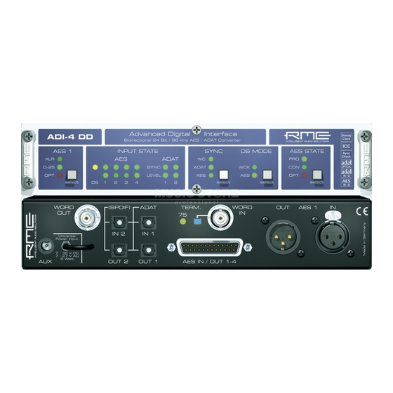
Word Clock Professional Double Speed ADAT Consumer Audio level Optical output Rear Wordclock ADAT/SPDIF Wordclock AES 1 input / output outputs input output Power supply AES inputs and outputs connector via D-sub 25 pin User's Guide ADI-4 DD © RME... -
Page 22: Connector Pinouts
3/4- 5/6+ 5/6- 7/8+ 7/8- D-Sub Signal 1/2+ 1/2- 3/4+ 3/4- 5/6+ 5/6- 7/8+ 7/8- D-Sub GND is connected to pins 2, 5, 8, 11, 16, 19, 22, 25. Pin 13 is not connected. User's Guide ADI-4 DD © RME... - Page 23 AES/EBU and SPDIF are biphase modulated signals, therefore polarity doesn't matter. Pins 2 and 3 are neither hot nor cold, they carry the same signal. But as AES3 uses a balanced trans- mission they are inverted in polarity. User's Guide ADI-4 DD © RME...
-
Page 24: Block Diagram
14. Block Diagram User's Guide ADI-4 DD © RME... -
Page 25: Warranty
All entries in this User’s Guide have been thoroughly checked, however no guarantee for correctness can be given. RME cannot be held responsible for any misleading or incorrect information provided throughout this manual. Lending or copying any part or the complete manual or its contents as well as the software belonging to it is only possible with the written permission from RME. - Page 26 For this the device has to be sent free to the door to: IMM Elektronik GmbH Leipziger Straße 32 D-09648 Mittweida Germany Shipments not prepaid will be rejected and returned on the original sender's costs. User's Guide ADI-4 DD © RME...
Need help?
Do you have a question about the ADI-4 DD and is the answer not in the manual?
Questions and answers