Table of Contents
Advertisement
Quick Links
One Technology Way • P.O. Box 9106 • Norwood, MA 02062-9106, U.S.A. • Tel: 781.329.4700 • Fax: 781.461.3113 • www.analog.com
Evaluating the
FEATURES
FMC connector for MII interface, MDIO signals, and status
signals
Accessible, surface-mount configuration resistors and dial
switches
Operates from a single, external 5 V supply
EVALUATION KIT CONTENTS
EVAL-ADIN1300FMCZ evaluation board
MDIO interface dongle
EQUIPMENT NEEDED
Power supply (choose one of the following):
5 V power supply rail to connect to the EXT_5V connector
5 V barrel adaptor to connect to the P4 plug
Ethernet cable
USB cable
PC running Windows 7 and upward
SOFTWARE NEEDED
Ethernet PHY software and GUI (available to download on
the
ADIN1300
product page)
DOCUMENTS NEEDED
ADIN1300
data sheet
PLEASE SEE THE LAST PAGE FOR AN IMPORTANT
WARNING AND LEGAL TERMS AND CONDITIONS.
ADIN1300
Robust, Industrial, Low Latency, and Low Power
10 Mbps, 100 Mbps, and 1 Gbps Ethernet PHY
EVAL-ADIN1300FMCZ
GENERAL DESCRIPTION
The EVAL-ADIN1300FMCZ allows simplified evaluation of the
key features of the
gigabit, 10 Mbps, 100 Mbps, and 1 Gbps, Ethernet physical layer
(PHY). The EVAL-ADIN1300FMCZ is powered by a single,
external, 5 V supply rail that can be supplied either via the
EXT_5V connector or via the P4 plug.
All chip supplies are regulated from the 5 V rail providing
supply rails required for AVDD3P3, VDD0P, and VDDIO.
The P3 field programmable gate array (FPGA) mezzanine
connector (FMC) connector is provided for connection to a
master FPGA system for the media access control (MAC)
interface and management data input/output (MDIO) control.
The P5 connector provides an alternative means for MDIO
control. The EVAL-ADIN1300FMCZ is fitted with a 25 MHz
crystal (Y1).
For complete specifications for the
ADIN1300
data sheet, which must be consulted in conjunction
with this user guide when using the EVAL-ADIN1300FMCZ.
Rev. 0 | Page 1 of 30
User Guide
ADIN1300
robust, industrial, low latency
ADIN1300
device, see the
UG-1635
Advertisement
Table of Contents

Related Manuals for Analog Devices EVAL-ADIN1300FMCZ


Summary of Contents for Analog Devices EVAL-ADIN1300FMCZ
-
Page 1: Features
5 V barrel adaptor to connect to the P4 plug The P5 connector provides an alternative means for MDIO Ethernet cable control. The EVAL-ADIN1300FMCZ is fitted with a 25 MHz USB cable crystal (Y1). PC running Windows 7 and upward... -
Page 2: Table Of Contents
Framechecker Tab ..............14 Revision History ................2 Cable Diagnostics Tab ............... 14 EVAL-ADIN1300FMCZ with Optional MDIO Interface Dongle Activity Window and Linking Status ........15 Connected ..................3 Activity Log Information Section ..........15 ... -
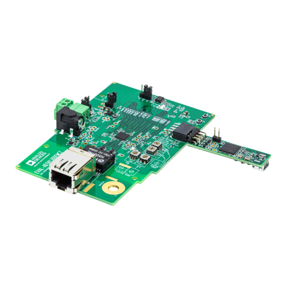
Page 3: Eval-Adin1300Fmcz With Optional Mdio Interface Dongle Connected
EVAL-ADIN1300FMCZ User Guide UG-1635 EVAL-ADIN1300FMCZ WITH OPTIONAL MDIO INTERFACE DONGLE CONNECTED Figure 1. Rev. 0 | Page 3 of 30... -
Page 4: Evaluation Board Hardware
JUMPER OPTIONS The VDDIO voltage rail defaults to 2.5 V with the installed A number of jumpers on the EVAL-ADIN1300FMCZ must be components, and may be adjusted if other VDDIO voltages are set for the required operating setup before using the EVAL- required by changing the value of the R16 resistor accordingly, ADIN1300FMCZ for evaluation. -
Page 5: On-Board Eeprom And Leds
Table 4 describes how S1 should be configured for the appropriate S4 PHY_CFG0 pin setting. The LED_0 pin is driven from the AVDD3P3 supply rail, see Figure 2. Figure 3. Simplified Overview of EVAL-ADIN1300FMCZ with MDIO Interface Dongle Connected Table 4. S1 Switch Positions... -
Page 6: Mdio Interface Dongle
ADIN1300FMCZ, DS7 and DS8 flash. The LEDs continue to The speed configuration is configured via two rotary switches, flash while the GUI is active and the EVAL-ADIN1300FMCZ is S3 and S4, and the media defined interface configuration is selected as the local board within the GUI. - Page 7 Forced Speed LED_0/COL/TX_ER/PHY_CFG0 Default configuration: PHY_CFG1/S3 = 1 or 2. Note that the EVAL-ADIN1300FMCZ boards are shipped in pairs with one board set to 1 and the other set to 2. PHY_CFG0 and S4 = 4, and LED_0 and S1 = 1.
-
Page 8: Software Overview
Ethernet PHY software and the installation of the USB Next (see Figure 8). communications drivers. Both installations must be complete before connecting the EVAL-ADIN1300FMCZ to the USB port of the PC to ensure that the evaluation system is properly recognized when connected to the PC. -
Page 9: Initial Setup
Select a location to install the Ethernet PHY software and INITIAL SETUP then click Install (see Figure 10). To set up the EVAL-ADIN1300FMCZ and use it with the Ethernet PHY software GUI, take the following steps: Connect a 5 V power supply to the EVAL-ADIN1300FMCZ via the EXT_5V connector or the 5 V barrel connector. -
Page 10: Using The Evaluation Software
Label Description Select Local section. Shows connected evaluation hardware. The board name shown corresponds to the MDIO interface dongle that is connected to the EVAL-ADIN1300FMCZ. User buttons. Link Properties tab. Use this tab to change the PHY configuration. Register Access tab. Allows the user read or write device registers. -
Page 11: Gui Detailed Overview
GUI DETAILED OVERVIEW BOARD DISPLAY SHOWING CONNECTED Software Power-Down and Power-Up EVAL-ADIN1300FMCZ HARDWARE Click Software Power Down to place the selected device into software power-down mode where the analog and digital circuits In the Select Local section (see Figure 12), a unique hardware are placed into a low power state. -
Page 12: Link Properties Tab
UG-1635 EVAL-ADIN1300FMCZ User Guide Reset Speed Mode Click Reset to use the dropdown menu to initiate different For the selected device, advertised speed or forced speed can be resets. The reset options include the following: chosen. The speed selection prepopulates the remaining user controls for the Link Properties tab with the following: ... -
Page 13: Register Access Tab
EVAL-ADIN1300FMCZ User Guide UG-1635 REGISTER ACCESS TAB CLOCK PIN CONTROL TAB The Browse tab within the Register Access tab allows the user Use this tab to control which clock is applied to the GP_CLK pin, to review the bank of registers and edit the register fields or bit and to enable the CLK25_REF pin (see Figure 21). -
Page 14: Framechecker Tab
UG-1635 EVAL-ADIN1300FMCZ User Guide FRAMECHECKER TAB CABLE DIAGNOSTICS TAB This tab provides access to the frame generator and frame The cable diagnostic feature allows the user to diagnose issues checker features of the ADIN1300 (see Figure 24). with the link. Various features within the device are available... -
Page 15: Activity Window And Linking Status
ACTIVITY LOG INFORMATION SECTION The activity log reports status information and register write issues to the selected EVAL-ADIN1300FMCZ board (see Figure 32). The activity log captures the activity in the GUI corresponding to the activity on the local PHY, which indicates the various reads, writes, and information on whether a link is established. -
Page 16: Loading A Script File
UG-1635 EVAL-ADIN1300FMCZ User Guide LOADING A SCRIPT FILE The register commands can be loaded with either the register name or the register address, as shown in the simple examples The GUI allows the user to load a sequence of register in the file. -
Page 17: Troubleshooting
Figure 35. Example Activity Log when MDIO Interface Dongle is Not Ethernet PHY software. Responding If the EVAL-ADIN1300FMCZ does not appear in the GUI HARDWARE TIPS window, ensure that the following steps have been competed: Ensure that power is applied to the MDIO interface dongle and ... -
Page 18: Layout Guidelines
Each pair must be routed together with trace widths the same throughout. Trace lengths must be kept equal where possible The EVAL-ADIN1300FMCZ consists of a 4-layer PCB: the top and any right angles on these traces must be avoided (use curves or layer, Layer 2, Layer 3, and the bottom layer. -
Page 19: Evaluation Board Schematics And Artwork
EVAL-ADIN1300FMCZ User Guide UG-1635 EVALUATION BOARD SCHEMATICS AND ARTWORK Figure 37. PHY Schematic Rev. 0 | Page 19 of 30... - Page 20 UG-1635 EVAL-ADIN1300FMCZ User Guide 100Ω DIFFERENTIAL; 5 MIL TRACES, 10 MIL SPACING ( 5 / 10 / 5 ); MATCH AND MINIMIZE TRACE LENGTH 100Ω DIFFERENTIAL; 5 MIL TRACES, 10 MIL SPACING ( 5 / 10 / 5 ); MATCH AND MINIMIZE TRACE LENGTH...
- Page 21 EVAL-ADIN1300FMCZ User Guide UG-1635 Figure 39. Power Supplies Rev. 0 | Page 21 of 30...
- Page 22 UG-1635 EVAL-ADIN1300FMCZ User Guide Figure 40. FMC Connector Rev. 0 | Page 22 of 30...
- Page 23 EVAL-ADIN1300FMCZ User Guide UG-1635 VBAT_DIG1 VBAT_ANA2 VBAT_ANA1 Figure 41. MDIO Interface Dongle Rev. 0 | Page 23 of 30...
- Page 24 UG-1635 EVAL-ADIN1300FMCZ User Guide Figure 42. Schematic Silkscreen, Top Figure 43. Schematic Silkscreen, Bottom Rev. 0 | Page 24 of 30...
- Page 25 EVAL-ADIN1300FMCZ User Guide UG-1635 Figure 44. Top Layer Figure 45. Layer 2, Ground Layer Rev. 0 | Page 25 of 30...
- Page 26 UG-1635 EVAL-ADIN1300FMCZ User Guide Figure 46. Layer 3, Power and Ground Layer Figure 47. Bottom Layer Rev. 0 | Page 26 of 30...
-
Page 27: Ordering Information
EVAL-ADIN1300FMCZ User Guide UG-1635 ORDERING INFORMATION BILL OF MATERIALS Table 7. Reference Designator Description Manufacturer Part Number C1, C10, C11, C15, C19, C21, Ceramic capacitors, 0.1 μF, 16 V, 10%, American Technical 530L104KT16T C23, C26, C54, C55, C57 to C62... - Page 28 UG-1635 EVAL-ADIN1300FMCZ User Guide Reference Designator Description Manufacturer Part Number PCB connector, straight, male, 2-pin Amphenol FCI 69157-102HLF header PCB connector, single-ended array, Samtec ASP-134604-01 male, 160-position, FMC PCB connector, CNCUI-PJ-002A_A, PJ-002AH-SMT-TR power jack Samtec SSW-104-02-T-D-RA PCB connector, 8-position, socket strip, double-row, right angled, 2.54 mm pitch...
- Page 29 EVAL-ADIN1300FMCZ User Guide UG-1635 Reference Designator Description Manufacturer Part Number S3, S4, S9 16 V, single-pole, 4 throw, rotary NIDEC COPAL CS-4-14NA switches, SP4T Electronics Transformer 1000BASE-T magnetic Pulse Electronics H5007NL modules IC robust, low latency gigabit Ethernet Analog Devices...
- Page 30 By using the evaluation board discussed herein (together with any tools, components documentation or support materials, the “Evaluation Board”), you are agreeing to be bound by the terms and conditions set forth below (“Agreement”) unless you have purchased the Evaluation Board, in which case the Analog Devices Standard Terms and Conditions of Sale shall govern. Do not use the Evaluation Board until you have read and agreed to the Agreement.
Need help?
Do you have a question about the EVAL-ADIN1300FMCZ and is the answer not in the manual?
Questions and answers