Table of Contents
Advertisement
Quick Links
Advertisement
Table of Contents

Related Manuals for COMAC FLEXY 70BS


Summary of Contents for COMAC FLEXY 70BS
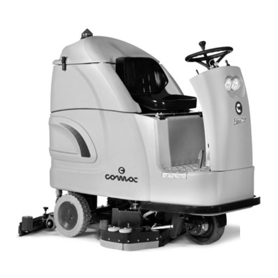
- Page 1 MANUAL USE AND MAINTENANCE FLEXY 70BS-85BS ED. 04-2009 Doc. 10016974 Ver.
- Page 2 The contained descriptions in the present publication are not binding. The company therefore reserves itself the right to bring in whatever moment possible organs changes, details or supplies of accessories, that it holds convenient for an improvement, or for any demand of constructive or commercial character.
-
Page 3: Table Of Contents
CONTENTS SERIAL NUMBER PLATE ................... 4 ON CONSIGNMENT OF THE MACHINE INTRODUCTORY COMMENT..................................4 TECHNICAL DESCRIPTION ..................................4 SYMBOLS USED ON THE MACHINE................................5 GENERAL SAFETY REGULATIONS ................................8 MACHINE PREPARATION..................................... 9 1. HANDLING THE PACKED MACHINE ..............................9 2. HOW TO UNPACK THE MACHINE ................................9 3.FITTING THE BATTERIES INTO THE MACHINE ............................... -
Page 4: On Consignment Of The Machine Serial Number Plate
On consignment of the machine Serial number plate When the machine is consigned to the customer, an immediate check must be performed to ensure all the material mentioned in the shipping documents has been received, and also to check the machine has not suffered damage during transportation. -
Page 5: Symbols Used On The Machine
SYMBOLS USED ON THE MACHINE Symbol denoting solenoid valve open Used to indicate the solenoid valve switch Symbol denoting solution tank empty Symbol denoting base rise/fall Used to indicate the base rise/fall manipulator Symbol denoting suction motor Used to indicate the suction motor switch Symbol denoting battery electric charging Symbol denoting charge level of batteries Used to indicate the charge level (from 1 to 4) of the batteries... - Page 6 SYMBOLS USED ON THE MACHINE Symbol denoting forward/backward drive selector Main switch symbol (key switch) Used on the instrument panel, to indicate the key switch for machine operation on (I) or off (O) Symbol denoting the manual/automatic operating mode switch Symbol denoting the indicator light incorrect operation Symbol denoting acoustic alarm Used to indicate the acoustic alarm button...
- Page 7 SYMBOLS USED ON THE MACHINE Label with instructions for using standard or concentrated detergents SYMBOLS USED IN THE MANUAL Indicates how to carry out the work correctly Indicates danger of gas exhalation and leakage of corrosive liquids Indicates the danger of fire Do not go near with free flames Indicates the disposal methods Respect the regulations...
-
Page 8: General Safety Regulations
The machine does not cause harmful vibrations When your COMAC machine has reached the end of its long working life, dispose of the materials it contains (especially oils, batteries and electronic components) in an appropriate manner, and bearing in mind that the machine itself was constructed using 100% recyclable materials (see the paragraph "MACHINE DISPOSAL"). -
Page 9: Machine Preparation
MACHINE PREPARATION 1. HANDLING THE PACKED MACHINE The machine is contained in specific packaging with a pallet for the handling with fork trucks. The packages cannot be placed on top of each other. The total weight is 410kg (without batteries) The Flexy 70 / 85 BS overall dimensions of the package are: 1550mm 1000mm... -
Page 10: Fitting The Batteries Into The Machine
MACHINE PREPARATION 3. FITTING THE BATTERIES INTO THE MACHINE The batteries must be housed in the special compartment beneath the recovery tank. They should be handled using lifting equipment that is suitable in terms of both weight and hook-up system. They must also satisfy the requirements of Standard CEI 21-5. The dimensions of the battery compartment are: 538 x 620 x H460mm. -
Page 11: Connecting The Battery Charger
MACHINE PREPARATION 5. CONNECTING THE BATTERY CHARGER The battery connector is placed under the operator's seat. The lower part (1), connected to the batteries, must be detached from machine connector (2) and hooked up to the battery charger connector for charging. The coupling connector (3) is consigned inside the bag containing this instruction booklet, and must be assembled on the cables of the battery charger as indicated in the instructions (see the battery charger manual). -
Page 12: Battery Charge Level Indicator
MACHINE PREPARATION 7. BATTERY CHARGE LEVEL INDICATOR The digital battery indicator has 4 fixed positions and a flashing one. The numbers which appear on the display show the approximate charge level. 4 = maximum charge, 3 = 3/4 charge, 2 = 2/4 charge, 1 = 1/4 charge, 0 = discharged batteries (flashing) ATTENTION! A few seconds after the appearance of the flashing “0”, the brush motor will switch off automatically. -
Page 13: Adjusting The Height Of The Splash Guard Rubber Supports
MACHINE PREPARATION 11. ADJUSTING THE HEIGHT OF THE SPLASH GUARD RUBBER SUPPORTS During operation, the splash guard of the base must touch the floor lightly To alter the height of the support, and therefore of the splash guard rubbers, tighten or loosen the regulating knobs (1) so the rubber is parallel with the floor. -
Page 14: Recovery Tank
MACHINE PREPARATION 13. RECOVERY TANK Check that the squeegee tube (1) and drainage tube are correctly positioned. Check that the plug (2) knob on the drainage tube is screwed 14. DETERGENT SOLUTION Unscrew the tank plug (1) and fill with clean water at a temperature of not more than 50°C. -
Page 15: Work
WORK PREPARING TO WORK 1. Carry out the operations to prepare the machine 2. Sit on the driver’s seat 3. Check the parking brake is released (1) 4. Connect the connector to the batteries (2) 5. Turn the key of the main switch (3) a quarter of a turn clockwise. The main green indicator light (4) on the instrument panel will immediately turn on and the display will show the battery charge level (5) 6. -
Page 16: Regulating The Automatic Water/Detergent Dosing System (Optional)
WORK REGULATING THE AUTOMATIC WATER/DETERGENT DOSING SYSTEM (OPTIONAL) The machine is supplied with the switches (on the instrument panel) already integrated. Two rubber caps are also supplied. Once the regulation has been made, you can remove the knobs and cover the holes with the rubber caps. -
Page 17: Overflow Device
WORK OVERFLOW DEVICE The machine is fitted with an overflow switch that intervenes when the recovery tank is full, causing the suction tube to close. In this case you must empty the tank. To start working again turn the main key- operated switch off and on again TRACTION This machine is equipped with electronically commanded traction, with three speeds... -
Page 18: Brakes
WORK BRAKES The machine has an electronic braking system. To brake, in normal conditions, just remove your foot from the accelerator pedal. If the service brake does not operate properly or in case of need (parking, danger, etc.) actuate the pedal-operated mechanical brake by pushing it down and pulling it towards yourself until the lever is hooked up (1). -
Page 19: At The End Of The Work
AT THE END OF THE WORK At the end of the work, and before carrying out any type of maintenance, perform the following operations: 1. turn off the tap 2. set the “AUTO/MAN” switch on manual (yellow indicator light off) 3. -
Page 20: Daily Maintenance
DAILY MAINTENANCE CLEANING THE RECOVERY TANK 1. Empty the tank through the hose, turning the knob a few turns and then pulling out the drain plug This operation must be carried out using gloves to protect against contact with dangerous solutions. 2. -
Page 21: Cleaning The Solution Tank And Filter
DAILY MAINTENANCE CLEANING THE SOLUTION TANK AND FILTER With the solution tank empty: 1. turn on the tap 2. unscrew and carefully rinse the filter 3. remove the plug from the solution tank refill opening 4. rinse the inside of the tank with a jet of water 5. -
Page 22: Weekly Maintenance
WEEKLY MAINTENANCE REPLACING THE REAR SQUEEGEE RUBBER If the squeegee rear rubber is worn and does not dry well, it is possible to change the drying edge, proceeding as follows: 1. push and rotate the fixing plates (1) 2. remove the rubber-pressing blade and the rubber itself 3. -
Page 23: Extraordinary Maintenance
4. Unthread the splash guard rubber, rotating it by 180° so the worn part can be replaced with a new one. If the splash guards are worn on all sides, replace them with new rubbers (contact the COMAC Technical Assistance Centre) 5. Reassemble everything, carrying out the above-mentioned operations in the... -
Page 24: Troubleshooting
TROUBLESHOOTING INSUFFICIENT WATER ON THE BRUSHES 1. Check the tap is turned on 2. Check the solenoid valve switch is on 3. Check there is water in the solution tank 4. Clean the solution filter THE SQUEEGEE DOES NOT DRY PERFECTLY 1. -
Page 25: The Suction Motor Does Not Function
6. Press the working operation command pedal to activate the brush motors. If the problem persists, contact the COMAC Technical Assistance Centre. IT IS IMPOSSIBLE TO RAISE OR LOWER THE BASE OR SQUEEGEE 1. The machine is fitted with electrical protection devices that control the base and squeegee ascent/descent motor reducers. -
Page 26: Electric Fuses And Thermal Cut-Outs
TROUBLESHOOTING ELECTRIC FUSES AND THERMAL CUT-OUTS The machine is fitted with the following electrical protection systems: power fuses arranged in the electrical box, to protect against short-circuiting thermal trip units arranged on the outside, on the column, to protect: • General 50 A trip unit for two base motors •... -
Page 27: Choosing And Using The Brushes
CHOOSING AND USING THE BRUSHES POLYPROPYLENE BRUSH (PPL) Used on all types of floors. Good resistance to wear and tear, and hot water (no greater than 60°C.). The Polypropylene brush is non-hygroscopic and therefore retains its characteristics even when working in wet conditions. ABRASIVE BRUSH The bristles of this type of brush are charged with highly aggressive abrasives. -
Page 28: Machine Disposal
MACHINE DISPOSAL MACHINE DISPOSAL To dispose of the machine, take it to a demolition centre or an authorised collection centre. Before scrapping the machine it is necessary to remove and separate the following materials and send them to the appropriate collection centres in accordance with the environmental hygiene regulations currently in force: •... -
Page 29: Ec Declaration Of Conformity
San Giovanni Lupatoto (VR), 05/02/2007 COMAC S.p.A. Legal representative Giancarlo Ruffo COMAC spa Via Cà Nova Zampieri, 5 – 37057 San Giovanni Lupatoto – Verona – ITALY Tel. +39 045 8774222 – Fax +39 045 8750303 – E-mail: com@comac.it or info@comac.it - www.comac.it...
Need help?
Do you have a question about the FLEXY 70BS and is the answer not in the manual?
Questions and answers