Sign In
Upload
Download
Table of Contents
Contents
Add to my manuals
Delete from my manuals
Share
URL of this page:
HTML Link:
Bookmark this page
Add
Manual will be automatically added to "My Manuals"
Print this page
×
Bookmark added
×
Added to my manuals
Manuals
Brands
COMAC Manuals
Scrubber
OPTIMA 85
Use and maintenance manual
COMAC OPTIMA 85 Use And Maintenance Manual
Scrubbing machines
Hide thumbs
1
2
Table Of Contents
3
4
5
6
7
8
9
10
11
12
13
14
15
16
17
18
19
20
21
22
23
24
25
26
27
28
29
30
31
32
page
of
32
Go
/
32
Contents
Table of Contents
Troubleshooting
Bookmarks
Table of Contents
Table of Contents
Contents
General Safety Regulations
Recharging the Batteries
Using the Machine
Deactivation of the Machine
Maintenance
Transport
Symbols Used on the Machine
Symbols Present on the Registration Plate
Symbols Printed on the Machine
Labels on the Machine
Symbols Present on the Command Panel
Symbols Present on the Control Panel
Symbols Used in the Manual
Purpose and Content of the Manual
Target Group
Storing the Use and Maintenance Manual
On Consignment of the Machine
Introductory Comment
Identification Data
Technical Description
Intended Use
Safety
Special Equipment
Registration Plate
Technical Data (International System)
Technical Data (Imperial System)
Brush Type
Preparation of Machine
Handling the Packaged Machine
How to Unpack the Machine
How to Move the Machine
Machine Safety
Type of Battery to be Used
Battery Maintenance and Disposal
Recharging the Batteries
Filling the Solution Tank with Water
Detergent Solution
Assembling the Squeegee Body
Assembling the Brush Head Body Brushes
User Seat Adjustment
Preparing to Work
Starting Work
Water Flow Adjustment Function
Detergent Solution Flow Adjustment Function (Cds Version)
Eco-Mode Function
Buzzer
Movement Speed Adjustment
Extra-Pressure Function Exerted on the Brushes
Brush Release Function
Dipped Headlights
Hour Meter
Battery Charge Level Indicator
Emergency Button
Alarm Screen
Service Brake
Overflow Device
At the End of the Work
Routine Maintenance
Emptying the Recovery Tank
Cleaning the Squeegee Body
Cleaning the Recovery Tank Filter-Float
Cleaning the Brush Head Body Brushes
Cleaning the Recovery Tank
Emptying the Solution Tank
Cleaning the Water System Filter
Cleaning the Vacuum Tube
Cleaning the Detergent Tank (Cds Versions)
Extraordinary Maintenance Work
Replacing the Squeegee Body Rubber Blades
Replacing the Brush Head Body Brushes
Adjustment Interventions
Adjusting the Squeegee Body's Rubber Blades
Disposal
Ec Declaration of Conformity
Troubleshooting
Browsing the Command Display Menu
Advertisement
Quick Links
1
Table of Contents
2
Maintenance
3
Alarm Screen
4
Troubleshooting
Download this manual
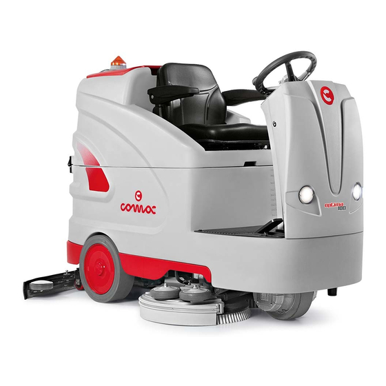
SCRUBBING MACHINES
USE AND MAINTENANCE MANUAL
ORIGINAL INSTRUCTION DOC. 10043695 - Ver. AD - 07-2018
Table of
Contents
Previous
Page
Next
Page
1
2
3
4
5
Advertisement
Table of Contents
Need help?
Do you have a question about the OPTIMA 85 and is the answer not in the manual?
Ask a question
Questions and answers
Related Manuals for COMAC OPTIMA 85
Scrubber COMAC OMNIA 26 Manual
(124 pages)
Scrubber COMAC OMNIA 26 Use And Maintenance Manual
Floor scrubber (28 pages)
Scrubber COMAC Optima 90 Use And Maintenance Manual
Scrubbing machines (32 pages)
Scrubber COMAC OPTIMA 100B Use And Maintenance Manual
Scrubbing machines (32 pages)
Scrubber COMAC OPTIMA 100 Use And Maintenance Manual
Scrubbing machines (32 pages)
Scrubber COMAC C85B-C100B Instruction Manual
(27 pages)
Scrubber COMAC ULTRA100 BS Use And Maintenance Manual
(64 pages)
Scrubber COMAC Innova Comfort Use And Maintenance Manual
Scrubbing machines (44 pages)
Scrubber COMAC SIMPLA 50 B Use And Maintenance Manual
(31 pages)
Scrubber COMAC Vispa 35B Manual Use And Maintenance
Scrubbing machine (20 pages)
Scrubber COMAC C85 ESSENTIAL Series Use And Maintenance Manual
Scrubbing machines (40 pages)
Scrubber COMAC Tripla 60B Use And Maintenance Manual
2009 year floor scrubber-dryer (32 pages)
Scrubber COMAC ANTEA 50 B Use And Maintenance Manual
Scrubbing machines (44 pages)
Scrubber COMAC Vega 2019 Use And Maintenance Manual
Scrubbing machines (40 pages)
Scrubber COMAC SCRUB 45D Use And Maintenance Manual
Scrubbing machines (24 pages)
Scrubber COMAC ANTEA 50 B Use And Maintenance Manual
Antea series; versa series scrubbing machines (64 pages)
This manual is also suitable for:
Optima 100
Optima 85b
Optima 100b
Table of Contents
Print
Rename the bookmark
Delete bookmark?
Delete from my manuals?
Login
Sign In
OR
Sign in with Facebook
Sign in with Google
Upload manual
Upload from disk
Upload from URL


Need help?
Do you have a question about the OPTIMA 85 and is the answer not in the manual?
Questions and answers