
Related Manuals for COMAC Optima 90


Summary of Contents for COMAC Optima 90
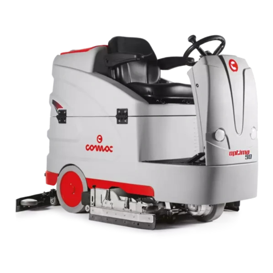
- Page 1 SCRUBBING MACHINES USE AND MAINTENANCE MANUAL ORIGINAL INSTRUCTION DOC. 10081741 - Ver. AA - 07-2018...
-
Page 3: Table Of Contents
CONTENTS CONTENTS .......................3 CLEANING THE RECOVERY TANK ..................24 GENERAL SAFETY REGULATIONS ............... 4 EMPTYING THE SOLUTION TANK ..................24 CLEANING THE WATER SYSTEM FILTER ................25 RECHARGING THE BATTERIES ....................4 CLEANING THE VACUUM TUBE ..................... 25 USING THE MACHINE ........................ 5 CLEANING THE DETERGENT TANK (CDS VERSIONS) ............ -
Page 4: General Safety Regulations
GENERAL SAFETY REGULATIONS The following symbols are used to indicate any potentially hazardous situations. Always read this information carefully and take the necessary precautions to protect any people and/or objects that may be present. Operator cooperation is paramount for accident prevention. No accident prevention programme can be effective without the full cooperation of the person directly responsible for the machine's operation. -
Page 5: Using The Machine
• Keep the battery charger's cable at a safe distance from any hot surfaces. • Never smoke in the machine's vicinity while the batteries are charging. • Before starting the charging operation, carefully read the use and maintenance manual of the batteries and the battery charger that you want to use. - Page 6 • The machine must only be powered with a voltage equal to that shown on the serial number plate. • Read the labels on the machine carefully. Do not cover them for any reason, and replace them immediately if they become damaged. •...
-
Page 7: Deactivation Of The Machine
• Before starting to work check that all the safety devices have been installed and are working correctly. • Before starting work check that the brakes and steering are working correctly. • Before starting work adjust the seat and steering wheel, and also the seat belt if there is one. DEACTIVATION OF THE MACHINE WARNING: •... - Page 8 All repairs must be carried out by qualified personnel. • Do not physically change the design characteristics of the machine. • Use spare parts supplied by Comac or by Comac service centres. • Wear personal protective equipment as required and as suggested in the manual.
-
Page 9: Transport
TRANSPORT WARNING: • Use hoists or jacks capable of supporting the weight of the machine. • Do not push or tow the machine without an operator on the seat who can control the machine. • The ramp gradient must not be such as to cause damage to the machine as it moves up onto the vehicle or from the vehicle to the ground. -
Page 10: Symbols Used On The Machine
SYMBOLS USED ON THE MACHINE SYMBOLS PRESENT ON THE REGISTRATION PLATE Direct current symbol: Used on the appliance's registration plate to indicate that the appliance is powered by a DC power supply. Battery symbol: Used on the appliance's registration plates to indicate the mass of the batteries used to power the appliance (expressed in Kg). The value refers to the batteries that the manufacturer offers. Maximum gradient symbol: Used on the registration plate of the device, to indicate the maximum gradient that can be safely handled by the device in work mode. -
Page 11: Symbols Present On The Command Panel
Braking system oil level check label: Located near the braking system oil basin, to remind the operator to check the level of oil in the basin. The bottom part of the label shows the recommended oil for the braking system. SYMBOLS PRESENT ON THE COMMAND PANEL Main switch symbol: Used on the command panel to indicate in which direction to turn the key to activate or deactivate the machine's general switch. -
Page 12: Symbols Used In The Manual
The descriptions contained in this document are not binding. The company therefore reserves the right to make any modifications at any time to elements, details, or accessory supply, as considered necessary for reasons of improvement or manufacturing/commercial requirements. The reproduction, even partial, of the text and drawings contained in this document is prohibited by law. The company reserves the right to make any technical and/or supply modifications. -
Page 13: Special Equipment
SPECIAL EQUIPMENT Each design is created with the aim of giving the customer a new reason to choose Comac spa products, this type of scrubbing machines in particular can be equipped with the following devices: • ECO-MODE: a device that decreases the noise level and lowers energy consumption. -
Page 14: Technical Data (Imperial System)
TECHNICAL DATA (IMPERIAL SYSTEM) OPTIMA 90BS Rated power 3340 Working width 34.25 Squeegee width 44.09 Working capacity, up to sq.ft/h 74916.81 Diameter and width of front brush Ø in x in 5.91 x 33.66 Diameter and width of rear brush Ø... -
Page 15: Preparation Of Machine
PREPARATION OF MACHINE HANDLING THE PACKAGED MACHINE Gross weight of machine with packaging is: • Optima 90BS= 410 Kg or else 904 lb The overall dimensions of the package are: • A= 1130 mm or 44.49 in • B= 1880 mm or 74.02 in •... -
Page 16: Recharging The Batteries
RECHARGING THE BATTERIES The batteries must be charged prior to the first use, and when they don't provide enough power for tasks that could formerly be performed without difficulty. ATTENTION: To avoid any permanent damage to the batteries, it is essential to avoid their complete discharge; begin recharging them within a few minutes of noting the “discharged batteries” signal. ATTENTION: Never leave the batteries completely run down, even if the machine is not being used. -
Page 17: Detergent Solution
DETERGENT SOLUTION After filling the solution tank with clean water add the liquid detergent to the tank in the concentration and manner indicated on the detergent manufacturer's label. To prevent the formation of an excessive amount of foam that could damage the vacuum motor, use the minimum percentage of detergent required. CAUTION: Protective gloves should always be worn when handling detergents or acidic or alkaline solutions, to avoid serious injury to the hands. -
Page 18: User Seat Adjustment
USER SEAT ADJUSTMENT The proper adjustment of the driving position provides a greater sense of comfort when using the machine. Seat backrest adjustment: Make sure you sit upright and that your back and that your lower back and spine are at 90°. Use the lever (1) located on the left side of the seat (Fig. 1) to adjust the backrest of the seat. -
Page 19: Starting Work
STARTING WORK To start working, do as follows: 1. Make all the checks listed in “PREPARING TO WORK”. 2. Sit in the driver's seat, to adjust the driving position read paragraph “USER SEAT ADJUSTMENT”. 3. Move the main switch (1) to position “I” and turn the key a quarter turn clockwise (Fig. 1). 4. -
Page 20: Water Flow Adjustment Function
WATER FLOW ADJUSTMENT FUNCTION The water flow function in the machine's water system is regulated by the button (1) on the control panel (Fig. 1). By pressing the button (1) for the first time, you can display in the control display the status of the water flow set in the machine at that precise moment (Fig. -
Page 21: Battery Charge Level Indicator
BATTERY CHARGE LEVEL INDICATOR The machine's control panel contains the control display. At the top right of the work screen, there is a graphic symbol (13) representing the battery charge level indicator (Fig. 14). The indicator is composed of 5 charge levels, each of which represents about 20% of residual charge. With a residual charge of 20% the graphic symbol starts to flash and after a few second it will appear in larger dimensions in the middle of the screen, under these conditions take the machine to the usual place to charge the batteries. -
Page 22: At The End Of The Work
AT THE END OF THE WORK At the end of the work, and before carrying out any type of maintenance, perform the following operations: 1. Select the TRANSFER mode using the knob (1) (Fig. 1) on the control panel. 2. Press the drive pedal (2) (Fig. 2) to begin moving the machine. 3. -
Page 23: Emptying The Debris Hopper
EMPTYING THE DEBRIS HOPPER To empty the debris hopper, proceed as follows: 1. Take the machine to the maintenance area. N.B.: The place designated for this operation must comply with current environmental protection regulations. 2. Make sure the machine has been secured (see the section titled “SECURING THE MACHINE”). -
Page 24: Cleaning The Recovery Tank
N.B.: If the polyurethane ring on the float body (Fig. 5) is excessively worn or damage contact the nearest service centre. Repeat the operations in reverse order to reassemble all the parts and move on the second float filter. CLEANING THE BRUSH HEAD BODY BRUSHES Careful cleaning of the brush guarantees better cleaning of the floor as well as a longer brush head gearmotor lifespan. -
Page 25: Cleaning The Water System Filter
CLEANING THE WATER SYSTEM FILTER In order to clean the water system's filter, do the following: Take the machine to the maintenance area. Make sure the machine has been secured (see the section titled “SECURING THE MACHINE”). CAUTION: Users are advised to always wear protective gloves, to avoid the risk of serious injury to hands. Tighten the outlet flow of the tap, turn the lever (1) on the back of the steering column anti-clockwise (Fig. -
Page 26: Extraordinary Maintenance Work
EXTRAORDINARY MAINTENANCE WORK REPLACING THE SQUEEGEE BODY RUBBER BLADES The careful cleaning of the whole vacuum unit ensures better drying and cleaning of the floor as well as a longer vacuum motor life. To carry out the cleaning of the squeegee body, proceed as follows: Take the machine to the designated maintenance place. -
Page 27: Adjustment Interventions
ADJUSTMENT INTERVENTIONS ADJUSTING THE SQUEEGEE BODY'S RUBBER BLADES The careful adjustment of the squeegee body rubber blades guarantees better cleaning of the floor. To adjust the squeegee body blades, proceed as follows: Sit on the driver’s seat. Insert the key (1) into the main switch on the control panel. Set the main switch to “I” (Fig. 1). Select the “SCRUBBING WITH DRYING”... -
Page 28: Ec Declaration Of Conformity
EC DECLARATION OF CONFORMITY The undersigned manufacturer: COMAC S.p.A. Via Maestri del Lavoro, 13 37059 Santa Maria di Zevio (VR) Declares under its sole responsibility that the products FLOOR SCRUBBING MACHINES mod. OPTIMA 90BS Comply with the requirements of the following Directives: •... -
Page 29: Browsing The Command Display Menu
BROWSING THE COMMAND DISPLAY MENU To access the programming pages it is necessary to turn on the machine keeping buttons (4) and (6) pressed (Fig. 1). The first general menu item will appear after the first screens. The active keys within the programming procedures are: Scroll: access to the next parameter. - Page 30 SETTABLE MENU DEFAULT DESCRIPTION VALUES 5 - 50 Allows to adjust the control display contrast. 0 - 10 Allows to adjust the control display brightness. Allows to exit the operator menu.
- Page 32 COMAC S.p.A. Via Maestri del Lavoro, 13 - 37059 Santa Maria di Zevio - Verona - ITALY Tel. 045 8774222 - Fax 045 8750303 - www.comac.it - com@comac.it Organisation certified by Q.C.B. Italia ISO 9001:2008, ISO 14001:2015, OHSAS 18001:2007...
Need help?
Do you have a question about the Optima 90 and is the answer not in the manual?
Questions and answers