
Subscribe to Our Youtube Channel
Related Manuals for COMAC ULTRA100 BS


Summary of Contents for COMAC ULTRA100 BS
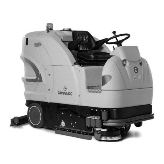
- Page 1 USE AND MAINTENANCE MANUAL ULTRA100 BS ULTRA100 GS BI-FUEL ED. 02-2012 ORIGINAL INSTRUCTIONS Doc. 10033331 Ver.
- Page 2 The descriptions contained in this document are not binding. The company therefore reserves the right to make any modifications at any time to elements, details, or accessory supply, as considered necessary for reasons of improvement or manufacturing/commercial requirements. The reproduction, even partial, of the text and drawings contained in this document is prohibited by law.
-
Page 3: Table Of Contents
CONTENTS ON CONSIGNMENT OF THE MACHINE............................. 5 SERIAL NUMBER PLATE ................................. 5 INTRODUCTORY COMMENT ................................5 INTENDED USE ....................................5 COMBUSTION ENGINE TECHNICAL DATA (HONDA IGX 440) ......................5 TECHNICAL DESCRIPTION ................................6 SYMBOLS USED ON THE MACHINE ..............................7 ... - Page 4 DAILY MAINTENANCE ................................... 40 44. CLEANING THE SUCTION MOTOR FILTER ........................................40 45. CLEANING THE SQUEEGEE ..............................................40 46. CLEANING THE SOLUTION TANK FILTER ........................................41 47. CLEANING THE DEBRIS HOPPER AND HOPPER SUCTION FILTER ..............................41 ...
-
Page 5: On Consignment Of The Machine
On consignment of the machine Serial number plate When the machine is delivered to the customer, an immediate check must be performed to ensure all the material mentioned in the shipping documents has been received, and also to check the machine has not been damaged during transportation. -
Page 6: Technical Description
TECHNICAL DESCRIPTION ULTRA100 BS ULTRA100 GS BI-FUEL Working width (without side brush) Working width (with side brush) 1080 1080 Squeegee width 1265 1265 Working capacity, up to 8640 8640 No. / 1 / 340 1 / 340 Side disc brush... -
Page 7: Symbols Used On The Machine
SYMBOLS USED ON THE MACHINE Symbol for the main switch or key switch (only on versions with a battery-operated motor) Used on the instrument panel, to indicate the key switch for machine operation on (ON-I) or off (OFF-0) Base/squeegee operating symbols Used to indicate the I-DRIVE programs selector Symbol denoting pressure applied to the brushes Used to indicate the knob for increasing the brush pressure... - Page 8 SYMBOLS USED ON THE MACHINE Symbol denoting incorrect functioning Used on the instrument panel to indicate the red warning light showing incorrect machine functioning Symbol denoting brake Used on the instrument panel to indicate the red warning light showing the absence of oil in the work braking system Symbol denoting brake Used on the instrument panel to indicate the red warning light showing parking brake on Symbol denoting solution tank empty...
- Page 9 SYMBOLS USED ON THE MACHINE Symbol for sideways movements of the side brush Used on the instrument panel to indicate the green warning light, showing that the side brush has returned to its normal position Symbol indicating movement of the squeegee unit Used on the instrument panel to indicate the green warning light showing the brush head has reached its operating position Symbol denoting left-hand suction motor Used on the instrument panel to indicate the green warning light showing that the left-hand suction motor is in operation...
- Page 10 SYMBOLS USED ON THE MACHINE Label warning that squeegee should be cleaned every day Label warning that recovery tank and solution tank should be cleaned every day Symbol indicating the position for inserting the battery charger connector (only on battery versions) Symbol denoting tap regulation Used on the central panel of the steering cover, to indicate the tap lever to regulate the water Label warning operator to take safety measures to avoid damage to limbs...
- Page 11 SYMBOLS USED ON THE MACHINE Label indicating the position of the recovery tank drain pipe Indicates the maximum gradient Indicates the risk of burns due to the hot surface Indicates the display service screen confirmation button Indicator showing battery charge level on the upper line and hour meter on the lower line Indicator showing the type of hour meter (total) on the upper line and the type of service (none) on the lower line Indicator showing the type of technology of the batteries used (lead) Label with instructions for the use of standard or concentrated detergents (CDS system only)
- Page 12 SYMBOLS USED ON THE MACHINE Label with Ph value of the detergent to use (CDS system only) Symbol indicating regulation of water and detergent quantity (CDS system only) Used on the left-hand panel, to indicate the knobs for adjusting the percentage level of detergent dissolved in the water, and the level of water distributed on the brushes Detergent symbol (CDS system only) Used on the detergent tank cap, to indicate the presence of chemical substances...
-
Page 13: General Safety Regulations
GENERAL SAFETY REGULATIONS The regulations below must be carefully followed in order to avoid harm to the operator and damage to the machine. WARNING: Read the labels on the machine carefully. Do not cover them for any reason and replace them immediately if they become damaged. ... -
Page 14: Machine Preparation
The machine is contained in specific packaging with a pallet for the handling with fork trucks. The packages cannot be placed on top of each other. The total weight of the machine with packaging is 930kg (Ultra100 BS without batteries). The total weight of the machine with packaging is 1030kg (Ultra100 GS without cylinder). - Page 15 MACHINE PREPARATION 4. 3-way switch to set working speed 5. Main key switch (battery versions) 6. 3-way switch to set force applied to brushes during operation 7. Display service confirmation button 8. Battery level / hour-counter display 9. Working program adjustment switch, I-Drive device Choose the desired operating program with the I-Drive device: A.
-
Page 16: Steering Column Components
MACHINE PREPARATION 16. Green warning light indicating that the main switch of the machine is active 17. Green warning light indicating that the machine headlights are on 18. Green warning light indicating that the solenoid valve is in operation 19. Green warning light indicating that the brush head motor is in operation 20. -
Page 17: Footboard Components
MACHINE PREPARATION The components of the steering column (right side) are as follows: 28. Green warning light indicating that the main switch of the machine is active (on versions with combustion engine) 29. Knob for adjusting the combustion engine rpm (on versions with combustion engine) 30. -
Page 18: Machine's Rear Components
MACHINE PREPARATION The components on the front/side of the machine are identified as follows: 39. Step to assist getting on to machine The components on the rear/side of the machine are identified as follows: 40. Suction cover release hinge 41. Recovery tank release hinge 8. -
Page 19: Machine's Front Components
MACHINE PREPARATION 48. Rear lights 9. MACHINE'S FRONT COMPONENTS The front components of the machine are identified as follows: 49. Headlights 10. TYPE OF BATTERY To power the machine it is necessary to use: liquidelectrolyte lead traction batteries; sealed traction batteries with gas recombination or gel technology. OTHER TYPES MUST NOT BE USED. -
Page 20: Maintenance And Disposal Of The Combustion Engine
MACHINE PREPARATION 13. MAINTENANCE AND DISPOSAL OF THE COMBUSTION ENGINE WARNING: For the maintenance and disposal of the combustion engine, observe the instructions given by the engine manufacturer (for maintenance) and current environmental hygiene norms (for disposal). 14. MAINTENANCE AND DISPOSAL OF THE LPG CYLINDER WARNING: For the maintenance and disposal of the LPG cylinder, observe the instructions given by the cylinder manufacturer (for maintenance) and current environmental hygiene norms (for disposal). -
Page 21: Connecting The Batteries And Battery Connector (Battery Version)
3. Connect the battery connector cable to the machine connector WARNING: You are advised to have the electric connections made by a qualified, COMAC-trained technician. WARNING: You are advised to always wear protective gloves, to avoid the risk of serious injury to your hands. -
Page 22: Indicator For Battery Charge Level And Hour Meter (Battery Version)
MACHINE PREPARATION The coupling connector of the battery charger is supplied inside the bag containing this instruction booklet, and must be fitted to the battery charger cables as shown in the instructions. WARNING: This process must be carried out by qualified personnel. Incorrect connection of the connector may cause machine malfunctions. -
Page 23: Connecting The Lpg Cylinder (Combustion Engine Version)
MACHINE PREPARATION 3. Lift the handle (3) to access the motor compartment 4. Raise the seat mounting plate by turning it as far as it will go 5. With regard to the safe filling of the combustion engine fuel tank, you must scrupulously observe the indications given in the motor use and maintenance manual (supplied with the machine) WARNING: The machine does not have a fuel level indicator, so you must always check the level before using it. -
Page 24: Hour Meter (Version With Combustion Engine)
MACHINE PREPARATION 5. Tighten the tube (7) to the tap (3). Remember to insert the seal that's supplied with the cylinder 6. Fully open the cylinder tap (3) 21. HOUR METER (VERSION WITH COMBUSTION ENGINE) On the instrument panel of the machine there is a display (1) indicating the effective number of working hours. -
Page 25: Working Forward Speed
MACHINE PREPARATION To engage the parking brake pull the lever (4) located near the seat, the red warning light (3) on the instrument panel will come on. 24. WORKING FORWARD SPEED This machine is equipped with electronic traction control. To move the machine, after turning the ignition key to "ON - I", you must select the direction of movement by operating the switch (1) located on the instrument panel. -
Page 26: Solution Tank
MACHINE PREPARATION 27. SOLUTION TANK Remove the filler plug (1) at the back of the seat and check that the solution filter is installed properly. Check that the drain pipe cap (2) located at the rear of the machine is properly closed. WARNING: The recovery tank must be completely empty each time the solution tank is filled. -
Page 27: Detergent Regulation (Version Without Cds)
MACHINE PREPARATION 5. Check that the quick coupling (4) under the detergent tank is properly inserted. 6. Unscrew the cap (3) of the tank on the right-hand side of the machine and fill with liquid detergent as indicated on the label supplied with the machine. Check the screw cap is well closed, to avoid any liquid leaking out while the machine is being used. -
Page 28: Detergent Regulation (Version With Cds)
ATTENTION: before regulating the solution, check there is detergent in the inner can, and that the side water tap is turned on. To resolve any malfunctioning of the CDS system, contact the COMAC assistance centre. WARNING: If the CDS system fails to function, or you want to work without this device, turn the lever of the tap (4) - on the front right-hand side of the machine - clockwise. -
Page 29: Assembling The Squeegee
MACHINE PREPARATION 33. ASSEMBLING THE SQUEEGEE The squeegee, that for reasons of packaging comes disassembled from the machine, must be assembled while assembling the machine. Proceed as follows for assembly: 1. Make sure the squeegee unit is raised, and that the selected work programme is "Transport" (position 2. - Page 30 MACHINE PREPARATION 5. Use a suitable tool to remove the right-hand splash guard pre-assembly (2), loosening the screws (3) that fix it to the brush head 6. Remove the nuts (4) from the right-hand carter 7. Remove the screw (5) from the right-hand carter 8.
-
Page 31: Side Brush Assembly
MACHINE PREPARATION 9. Remove the right-hand carter (7) from the brush head unit, and place it on the ground 10. Push the rear brush into the tunnel until it couples with the drive hub on the opposite side of the tunnel WARNING: Pay attention to the direction of the brush bristles during assembly, the point of the brush viewed from the above should be towards the front of the... -
Page 32: Detergent Pump Priming (Versions With Cds)
MACHINE PREPARATION 5. With the brush head up, insert the brush in the brush-holder plate seat, and turn it clockwise until the three studs are inserted in the notches on the plate itself. Turn, so the stud is pushed towards the coupling spring and the plate is locked in place WARNING: Check the brush is correctly inserted. -
Page 33: Work
“service” setting (in this case there is no setting) 8. The second screen displays what battery technology has been set for machine operation; in this case it is lead batteries (to set another type of battery - for instance gel - contact the qualified, COMAC-trained personnel) 9. - Page 34 WORK If you have a combustion engine version, before starting to work you must: 1. Make sure the recovery tank is empty, otherwise empty it completely 2. Check the parking brake is engaged; if it is not, engage it by means of the lever (3) near the left side of the seat 3.
- Page 35 WORK After starting up the machine, proceed as follows: 1. Choose the desired operating program with the I-Drive device: A. Transfer: movement of the machine without working B. Drying: use the squeegee only C. Washing / Drying: use both the brushes and the squeegee D.
- Page 36 WORK For the battery version, as the batteries run out, the battery charge indicators on the command display will go blank. When the batteries are fully discharged, the brush motor automatically switches off, so it is necessary to recharge them as soon as possible. A residual charge remains available to complete the drying process and to move the machine to the charging point;...
-
Page 37: Movement Of The Side Brush
WORK When the brush motor overload limit is exceeded, the red warning light (17) on the instrument panel begins to flash. After a few seconds the motor stops and the indicator light of the brush switch goes off. To restart the motor, turn the main switch key off and on again. If the motor stops again, check the reason of the overload in order to prevent damage to the motor. -
Page 38: At The End Of The Work
AT THE END OF THE WORK 43. AT THE END OF WORK At the end of work, and before carrying out any type of maintenance, perform the following operations: 1. Close the tap (1) for machine versions without the CDS system or turn the knobs (2-3) to OFF for machine versions with the CDS system Turn the I-DRIVE selector to the “Transfer”... - Page 39 AT THE END OF THE WORK 13. Release the clamp (7) and pull on the handle (8) to remove the debris hopper; place it on the ground, then take it to the appropriate disposal point and empty it WARNING: This operation must be carried out using gloves to protect against contact with dangerous solutions.
-
Page 40: Daily Maintenance
DAILY MAINTENANCE PERFORM ALL MAINTENANCE OPERATIONS IN SEQUENCE 44. CLEANING THE SUCTION MOTOR FILTER Check the electric system connector is disconnected from the battery connector (for battery versions) or from the generator connector (for the combustion engine version) Ensure that the main switch is in the “0” position Ensure the parking brake is engaged Check the recovery tank is empty (if necessary, empty it) Release the recovery tank stop hinges (1) and rotate as far as possible... -
Page 41: Cleaning The Solution Tank Filter
DAILY MAINTENANCE After cleaning, replace the squeegee on its support: 1. Insert the squeegee right-hand pin (1) into the right-hand slot of the squeegee support (2), secure it by means of the handwheel (3) 2. Insert the squeegee left-hand pin into the left-hand slot of the squeegee support, secure it by means of the handwheel 3. -
Page 42: Daily Maintenance - Combustion Engine
DAILY MAINTENANCE 4. Check the parking brake is engaged. If it is not, engage it by means of the lever (1) 5. Release the clamp (2) and pull on the handle (3) to remove the debris hopper; place it on the ground, then take it to the appropriate emptying point WARNING: This operation must be carried out using gloves to protect against contact with dangerous solutions. -
Page 43: Checking The Motor Oil Level
DAILY MAINTENANCE 49. CHECKING THE MOTOR OIL LEVEL Using the combustion engine with insufficient oil may seriously damage it. You are therefore advised to check the level at least once a day, in the following way: 1. Check the parking brake is engaged; if it is not, engage it by means of the lever (1) near the left side of the seat 2. -
Page 44: Weekly Maintenance
WEEKLY MAINTENANCE 51. CLEANING THE SUCTION HOSE Whenever suction seems to be unsatisfactory, check that the suction tube is not obstructed. If necessary clean with a jet of water as follows: 1. Connect the electric system connector to the battery connector (for battery versions) or to the generator connector (for versions with a combustion engine) 2. -
Page 45: Cleaning The Solution Tank
WEEKLY MAINTENANCE 7. Release the recovery tank stop hinges (4), located at the side of the tank 8. Rotate the recovery tank as far as it will go. Release the suction cover stop hinges (5) on the side of the cover 9. -
Page 46: Cleaning The Solution Tank Filter
WEEKLY MAINTENANCE 1. Remove the right-hand carter (2) by unscrewing the nuts (3) 2. Disconnect the quick release coupling (4) located behind the side cover, to prevent damage to the coupling itself 3. Remove the detergent tank (5) by unscrewing the nuts (6) 4. -
Page 47: Cleaning The Cylindrical Brushes
WEEKLY MAINTENANCE 56. CLEANING THE CYLINDRICAL BRUSHES Proceed as follows for cleaning: 1. Make sure the brush head unit is raised off the ground (if necessary, turn the I-DRIVE selector to the “Transfer” position to raise both the brush head and the squeegee) 2. -
Page 48: Cleaning The Side Brush
WEEKLY MAINTENANCE 9. Remove the right-hand carter (7) from the brush head unit, and place it on the ground 10. Take the rear brush out of the tunnel and rest it on the ground. Clean it with a jet of water 11. -
Page 49: Cleaning The Detergent Solution Distribution Basin
WEEKLY MAINTENANCE 5. Turn the knobs (2) on the brush head unit, to adjust the height of the side splash guards During working operation, the side rubber splash guard is slightly but evenly tilted outwards (by about 5mm) along its whole length. 59. - Page 50 WEEKLY MAINTENANCE 6. Remove the screw (4) from the right-hand carter 7. Remove the tube (5) connected to the distribution basin cover 8. Push the distribution basin towards the left side of the machine, then lift it and remove it from the brush head unit 9.
-
Page 51: Extraordinary Maintenance
EXTRAORDINARY MAINTENANCE 60. REPLACING THE CYLINDRICAL BRUSHES If the cylindrical brushes in the brush head base are worn, they will no longer clean the floor efficiently. To replace them, proceed as follows: 1. Make sure the brush head unit is in its idle position (if necessary, turn the I-DRIVE selector to the “Transfer”... -
Page 52: Replacing The Side Brush
EXTRAORDINARY MAINTENANCE 9. Remove the right-hand carter (7) from the brush head unit, and place it on the ground 10. Take the rear brush out of the tunnel and rest it on the ground. Push the new brush in, until it couples with the drive hub on the opposite side of the tunnel WARNING: Pay attention to the direction of the brush bristles during assembly, the point of the brush viewed from the above should be towards the front of the... -
Page 53: Replacing The Front Squeegee Rubber
EXTRAORDINARY MAINTENANCE 5. With the brush head up, release the brush from the brush-holder plate seat, and turn it anticlockwise until the three studs slip out of the notches on the plate itself. Turn, so the stud is pushed away from the coupling spring WARNING: You are advised to always wear protective gloves, to avoid the risk of serious injury to your hands. -
Page 54: Replacing The Rear Squeegee Rubber
EXTRAORDINARY MAINTENANCE 63. REPLACING THE REAR SQUEEGEE RUBBER If the squeegee rear rubber is worn and does not dry well, it is possible to change the drying edge using one of the 4 edges of the rubber. This can be done with the squeegee removed, proceeding as follows: 1. -
Page 55: Replacing The Splash Guard Rubber Of The Side Brush
EXTRAORDINARY MAINTENANCE 5. Use a suitable tool to remove the rubber-pressing blade (2), loosening the screws (3) that fix it to the splash guard support. 6. Take the rubber (4) out, and turn or replace it 7. To replace the rubber, proceed in reverse order 8. -
Page 56: Replacing The Starter Battery
EXTRAORDINARY MAINTENANCE 4. Fully close the cylinder tap (3) 5. Remove the straps (5) by releasing the springs (6) from the screws (7) on the cylinder support, then take off the cylinder 6. Position the new cylinder as shown in the figure. If it is in the right place, the tap (3) will be on the left side of the machine 7. -
Page 57: Washing The Dosing System (Versions With Cds)
EXTRAORDINARY MAINTENANCE 5. Lift the handle (2) to access the motor compartment 6. Turn the seat mounting plate as far as it will go 7. Use a suitable tool to disconnect the battery from the machine system WARNING: The first cable to be disconnected is the “+” pole, followed by the “-“... - Page 58 EXTRAORDINARY MAINTENANCE 5. Unscrew the cap of the detergent canister (1) and fill it with clean water 6. Refit the cap of the detergent tank 7. Check there is clean water in the solution tank 8. Check that the tap lever is fully opened, the lever is positioned at the rear of the machine 9.
-
Page 59: Troubleshooting
TROUBLESHOOTING 69. THE MACHINE DOES NOT START 1. Check the batteries are charged (battery version) 2. Check the starter battery is charged (combustion engine version) 3. Check the starter battery is connected to the machine system (combustion engine version) 4. Check the electric system connector is connected to the battery connector (battery version) 5. -
Page 60: The Brush Motor Does Not Work
With the dosing system out-of-use, the water flow is regulated via the tap on the steering column. Contact a COMAC authorised dealer to have the system repaired. 79. ALARMS The machine is fitted with a flashing warning light (1) for diagnosing faults in the traction motor control system. -
Page 61: Disposal
DISPOSAL To dispose of the machine, take it to a demolition centre or an authorised collection centre. Before scrapping the machine it is necessary to remove and separate the following materials and send them to the appropriate collection centres in accordance with the environmental hygiene regulations currently in force: ... -
Page 62: Choosing And Using The Brushes
CHOOSING AND USING THE BRUSHES POLYPROPYLENE BRUSH (PPL) Used on all types of floors. Good resistance to wear and tear, and hot water (no greater than 60°C). The Polypropylene brush is non-hygroscopic and therefore retains its characteristics even when working in wet conditions. NYLON BRUSH Used on all types of floors. -
Page 63: Ec Declaration Of Conformity
Via Maestri del Lavoro, 13 37059 Santa Maria di Zevio (VR) declares under its sole responsibility that the product ULTRA100 BS FLOOR SCRUBBING MACHINES comply with the requirements of the following Directives: 2006/42/EC: Machinery Directive 2006/95/EC: Low Voltage Directive ... -
Page 64: Ec Declaration Of Conformity
EC DECLARATION OF CONFORMITY The undersigned manufacturer: COMAC S.p.A. Via Maestri del Lavoro, 13 37059 Santa Maria di Zevio (VR) declares under its sole responsibility that the product ULTRA100 GS FLOOR SCRUBBING MACHINES comply with the requirements of the following Directives: ...
Need help?
Do you have a question about the ULTRA100 BS and is the answer not in the manual?
Questions and answers