
Subscribe to Our Youtube Channel
Summary of Contents for JENESIS SHS Series
- Page 1 ISIEVİ Makina Sanayi ve Ticaret Limited Şirketi İkitelli OSB Eskoop Sanayi Sitesi C7-4 Blok No : 479 Başakşehir - İstanbul - TÜRKİYE Tel : +90 212 595 16 56 ● Fax : +90 212 595 42 39 www.jenesis.com.tr●info@jenesis.com.tr...
-
Page 2: Table Of Contents
PAGE TABLE OF CONTENTS ASSEMBLY & MAINTENANCE & WARRANTY ASSEMBLY WHICH MUST BE DONE ON-SITE a – Putting the Steam Generator in Place b – Burner Fuel Line Connection c – Smokestack Connection d – Steam Connection e – Condensate Return Connection f –... -
Page 4: Assembly & Maintenance & Warranty
Installation, Operating and Maintenance Instructions, Warranty Certificate, Operating Principle ✓ Jenesis Steam Generators are delivered with one operating instructions folder. ✓ The folder contains the installation instructions, the general operating and maintenance instructions for the steam generator, the operating instructions for all parts used on the steam generator (burner, pump, etc.) and the warranty documents. -
Page 5: Assembly Which Must Be Done On-Site
PLACEMENT & CONNECTIONS ✓ WARNING!!! For the commissioning of your steam generator, several assemblies and connections must be made on site. You must send the photos of the gas opening certificate and the installations / connections made on site (steam installation, condensate installation, water installation, electricity installation, blowdown installation and smokestack connection) to our company. -
Page 6: B - Burner Fuel Line Connection
b - Burner Fuel Line Connection For Burners Functioning with Liquid Fuel ✓The installation of fuel line system to the indicated parts of the burner. ✓Use preheating tank in the heater and fuel lines on the Fuel-Oil tank. ✓Use a heater on the preheating tank. ✓Use valve and filter on the fuel feed installation. - Page 7 For Burners Functioning with Gaseous Fuels ✓The pressure of the gas being fed to the burner must have an appropriate value. (For the natural gas, this value is 21 millibars or 300 millibars.) ✓A suitable manometer should be used at a place close to the burner, on the gas inflow line of the burner.
-
Page 8: C - Smokestack Connection
c – Smokestack Connection ✓In the production of the smokestack, it is necessary to choose the diameter of the smokestack according to the fuel to be used. ✓Best possible production of the smokestack is necessary for the release of gas waste, for the burner to burn in the effectively and for your vapor generator to function with the highest efficiency. - Page 9 d – Vapor Connection ✓The best quality of the steam produced in the steam generator depends on the quality of the steam installation in the process. ✓The steam generator steam outlet valve size is given in the table below. The steam installation must always be one dimension above the steam outlet diameter used.
-
Page 10: D - Steam Connection
Steam Distribution Connection Diagram Buhar Dağılım Kollektörü... -
Page 11: E - Condensate Return Connection
e – Condensate Return Connection ✓Attach the condensate return line you are going to use in your process to the indicated entry on the condensate tank, after checking the necessary installation slopes. ✓Use suitable types and diameters of steam traps on your machine’s condensate outlets. ✓Condensate return diameters should be one diameter less than the diameter of gas installation entering to the unit. - Page 12 Condensate Return Connection Diagram...
-
Page 13: F - Electric Connections
f – Electricity Connection ✓Compact electric control panel is used on the steam generator. ✓All the control elements on the steam generator are connected to the electric control panel. ✓The process to be performed on-site on the electrical control panel is to connect the mains electricity (380V, 50Hz) to the R, S, T and neutral terminals left in the panel. -
Page 14: G - Vent Connection
g – Vent Connection ✓With the return of the condensate, 10% flash steam is delivered to the condensate tank. If this flash steam generation is not carried out of the condensate tank, it creates pressure in the tank and causes deformation. ✓At the same time, the flash steam increases the condensate tank water temperature to very high values, in which case overheated water will damage your feed pump. - Page 15 Vent Connection and Blowdown Connection Diagram...
-
Page 16: I - Safety Valve Connection
i – Safety Valve Connection ✓Safety valve is located on the vapor generator vapor outlet separator section. ✓When the pressure of the vapor generator passes the maximum operating pressure, safety valve discharges the surplus vapor and releases it to outside. ✓During the process of connections being done in place, safety valve should be taken to a dead spot and outside where people cannot be harmed. -
Page 17: J- Water Softening Device Connection (Optional)
j – Water Softening Device Connection ✓At the entrance of the water softener, there is a sediment filter, valve and manometer which are left by the factory. ✓The on-site connection is to connect the mains water to the valve on the inlet of the water softener. -
Page 18: Usage And Maintenance Instructions
– Introduction ✓Thank you for choosing ISIEVİ. ✓In this brochure, the assembly, usage and maintenance instructions of JENESIS SHS Type Vapor Generators are found, which are produced by ISIEVİ. ✓If you wish to use your device with high efficiency, comfortably and without any problems, observe the directives in this brochure carefully. -
Page 19: C - Warranty And Service
It has a highly advanced security equipment. The body of the steam generator is insulated by covering the static powder coated hair on rock wool. ✓With JENESIS Steam Generators, high efficiency monoblock burners with widespread service networks which have CE and TSE are preferred. SPECK triplex piston pumps are used as feed water pumps. -
Page 20: E - Operation Conditions
e – Operating Conditions ✓Type SHS Vapor Generators are designed to generate vapor. ✓Water should be supplied with appropriate hardness through the feed water inlet. ✓The feed water inlet hardness value used should be 0 ˚Fr. ✓Daily, weekly and monthly controls and maintenance should be carried out according to the instructions for use. -
Page 21: H - Feed Water Characteristics
h – Feed Water Characteristics ✓Considering a lime furring of 1 mm. thickness causes a 7% fuel loss; for a long-lasting and efficient operation of your Steam Generator, feed water input hardness value should be 0˚Fr hardness. BOILER SOFT WATER CONDENSATE ANALYZES BOILER LIMITS... -
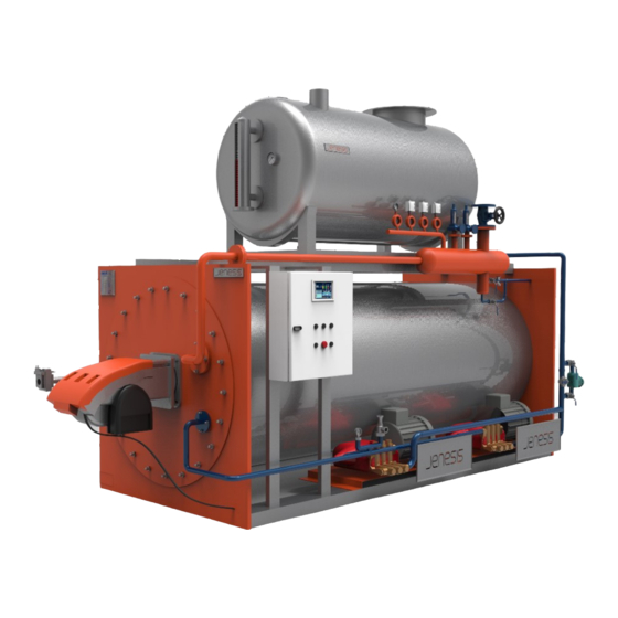
Page 22: I - Steam Generator Sections
ATTENTION!!! Steam Generator, i – Jenesis Vapor Generator Sections steam installation, condensate installation ✓Generator main body and the process in which the steam will be ✓Combustion chamber used may contain various wastes from production; since they newly ✓Front cover refractory manufactured. -
Page 23: Safety & Control
SAFETY AND CONTROL Safety measures have been taken in case the used steam exceeds the maximum operating temperature and pressure. These are; Safety Switch If the device is single-stage, it has one operating and one safety switch. The safety switch turns the burner on or off according to the pressure it takes from the produced steam. -
Page 24: Warranty Conditions
WARRANTY CONDITIONS Warranty Duration: The steam generator and all its parts are Consumer Rights: In the event of failure of the product due to defects warranted against defects in materials and workmanship for a in materials and workmanship within the warranty period; the product period of 2 (two) years from the date of delivery. -
Page 25: Start-Up
Commissioning of the Vapor Generator NOTE : The operating instructions folder contains a 3-page operating instruction to be hung in the workspace. A) Controls Which Must Be Done Before Start-Up 1 - Perform the hardness analysis of the water to be used. It must be 0 F !!! Before starting the steam generator, hardness analysis of the water must be performed and 0 F should be seen. - Page 26 2 - Check the fuel line for fuel. * For liquid fuel devices, verify that there is fuel in the fuel tank to which your fuel line coming to the burner is connected. * For gas-fired appliances, check the gas pressure at the inlet of the burner. (Figure 4) Figure 4 Figure 4 3 - Check the condensate tank for water.
- Page 27 4 - Check if there is a closed valve on the supply system. For example, fuel supply valve, condensate tank filling installation, pump supply installation. Before starting the steam generator, check that the valves on the device are in operational condition. First, the fuel valve must be opened.
- Page 28 6 - Check that the oil level is within the proper range and that water is not mixed into the oil from the oil level dipstick of the feed water pump. Before starting the steam generator, the pump oil is checked from the Speck pump dipstick. The pump oil level is normal at the points between the top and bottom paddles of the dipstick.
- Page 29 7 - Change the pump oil every 3 months. Type of oil to be used is SAE 90 GL 4 Speck pump oil is changed every 3 months. SAE 90 (gear oil 90) GL 4 (refers to the field of application) must be use as pump oil.
-
Page 30: B - Start-Up
B) Running the Steam Generator 1 – Close the main steam valve. 2 – Open the steam trap by-pass valve. 3 – Switch on the main switch 4 – Turn on the burner switch and supply electricity to the on the electrical control panel. system. - Page 31 5 – Turn the pump switch on the electrical control panel to the initial operating (MANUEL) position. 6 – Observe the operation of the pump. The pump will start to fill the coil. Continue this process until the first start-up valve (By- Pass) receives water.
- Page 32 NOTE : Check the pump pressure from the pressure gauge on the pump during the initial filling. The pressure should be between bars depending on the steam generator capacity. If higher pressures are encountered, this is a precursor to the formation of blockage in the coil.
- Page 33 9 – The burner will start operating. Check the burner flame through the sight glass. 10 – Wait until the steam temperature reaches 105 ˚C and the water from the bypass valve outlet runs out.
- Page 34 11 – Introduce the steam into the process by slowly opening the main steam valve and then close the bypass valve. NOTE: It is expected that the sound will decrease when the passage sound of the steam is heard by opening the valve slightly.
-
Page 35: C - Stopping
C) Stopping the Steam Generator 1 – Set the 2 - After the pump switch on pressure value on the electrical the steam control panel to manometer is Manual “0”, (Manuel). Let the pump run until water comes Close the main steam valve Open the steam trap by-pass valve out of the by-pass valve outlet... - Page 36 3 - When you see 4 - Turn the water coming out burner control of the by-pass switch on the valve outlet, turn electric control the pump control panel to the off switch off via the position. electric control panel. 5 –...
-
Page 37: D - Fault Codes
D) Fault Code Descriptions, Causes and Solutions Failures in the steam generator are indicated by the “failure indicator” on the electrical control panel. Codes are represented by numbers. Operator can come to see the error code of the device, check and eliminate the malfunction, then reset and run the device again. - Page 38 Fault #1 - High Pressure Description : Indicates that the specified operation pressure is exceeded. Solution * The setpoint for which the safety pressure switch is set must be checked. * It may be set below the specified operating pressure. * The operating pressure switch may fail and the device may rise above the set pressure, reaching the value of the safety pressure switch.
- Page 39 Fault Nb. 2 - High Vapor Temperature Description : Steam generators are devices operated by pressure control. The steam thermostat on the electrical control panel is used to inform the temperature of the steam going into operation and is used for safety. The steam temperature increases according to the set operating pressure.
- Page 40 Check that the strainer on the pump supply system is clean. Check that the pressurization pump in front of the device feed water pump (Speck pump) is operating. The hydrometer at the pump outlet will help you understand whether the pump is working.
- Page 41 If there is no problem up 1 - First, we remove the 3 blind plugs of the speck pump ,which are situated horizontally. to this point, if the water comes to the inlet of the feed water pump (speck) but you cannot get water from the feed water pump outlet, the check valves of the piston pump must be...
- Page 42 Fault Nb. 3 - High Smokestack Temperature Description : The smokestack thermostat on the electrical control panel is used for information on the waste smokestack temperature and for safety purposes. The factory setting is 250 C set value. The fault indicates that the set value specified in the smokestack temperature thermostat is exceeded and the device increases to the high smokestack temperature.
- Page 43 Fault Nb. 5 - Inverter Malfunction Description : The inverter in the electrical control panel is used to operate the Speck pump motor at different speeds. When the inverter fault code (5) is displayed, refer to the inverter's main display. The fault code printed on the inverter main screen must be checked in the inverter fault codes manual in the device operating instructions folder.
- Page 44 Fault Nb. 6 - Pressurization Pump Malfunction Description : Thermal failure of the pressurization pump used to increase suction line pressure in front of the feed water pump (Speck pump). Pressurization Pump Hydrometer Pompa Termiği Fault Code Indicator Solution * Install the pressurization pump thermal inside the electrical control panel. The thermal is installed by pressing the blue button as shown in the picture.
- Page 45 Fault Nb. 7 - Burner Malfunction Description : Gas (Natural Gas, LPG, CNG, LNG etc.) or liquid (Fuel-Oil, diesel etc.) burners are used on the steam generator. Burner failures vary according to the type of fuel you are using. Burner malfunctioned and stopped for some reason.
-
Page 46: S. 37 - # 2 S. 38 - # 3 S. 41- # 5 S. 42 - # 6 S. 43- # 7 S. 44 - # 8 S
Fault Nb. 8 - Flow Switch - No Water Malfunction Description : Fault related to the Flow Switch located at the output of the feed water pump (Speck Pump). After the pump is activated, the pump flow is controlled by the flow switch. If the flow switch does not feel the passage of water within the specified time, the device switches off with fault number 8. - Page 47 PROBLEM DESCRIPTION POSSIBLE REASON SOLUTION Check whether the safety switch is set to a higher pressure Indicates that the specified operation Fault Nb. 1 High Pressure than the operation switch. pressure is exceeded. The thermostat setpoint, pump flow, condensate tank water level and pump strainer must be checked.
-
Page 48: Fast Start-Up
QUICK START INSTRUCTIONS Before Operation 1 - Perform the hardness analysis of the water to be used, it should be “0” 2 - Check the fuel line for fuel. 3 - Check the condensate tank for water . 4 - Check the supply system for closed valves. (Fuel supply valve, condensate tank filling installation, pump supply installation) 5 - Check the feed pump connections (oil, water) for leaks. -
Page 49: Daily Maintenance
STEAM GENERATOR DAILY, WEEKLY AND MONTHLY MAINTENANCE JENESIS SHS SERIES STEAM GENERATOR DAILY CONTROL AND MAINTENANCE 1 - Check whether there is 2 - Check that water is sufficient amount of salt in coming water the water softening device softener inlet. - Page 50 3 - Perform the hardness analysis of the water to be used. Empty the condensate tank if the water is not at the desired hardness. After manual washing of the water softener, fill condensate tank when hardness value is reached. 300 mbars 21 mbars 4 - Check the fuel line for fuel.
-
Page 51: Weekly Maintenance
JENESIS SHS SERIES STEAM GENERATOR WEEKLY CONTROL AND MAINTENANCE 1 - Check the salt level by opening the lid of the water softener salt tank and add salt if necessary. Water Softening Device Salt Tank 2 - Open and clean the filter at the inlet of the feed water... - Page 52 4 – Clean the dirt trap on the fuel line. 3 - The float of the condensate tank must be checked by hand movement. should Gas Filter Liquid Fuel Filter checked whether the float, which is reached by removing 5 - Remove and clean the the condensate tank cap, cuts sight glass.
- Page 53 Inlet Valve Bleeder Screw Body Nut (Purger) 6 - Replace the sediment filter at 7 - Clean the trap group dirt catcher. It should be the water softener inlet. Close the checked when the pressure is zero and the device is supply valve at the water softener cold.
-
Page 54: Monthly Maintenance
JENESIS SHS SERIES STEAM GENERATOR MONTHLY CONTROL AND MAINTENANCE 1 - Perform all weekly control and maintenance operations respectively. 2 - Empty the condensate tank to remove sediment, sludge and other deposits. Refill the condensate tank. Tank Cover Tank with cover removed Tank Blowdown Valve 3 - Clean the salt tank of the water softener.
Need help?
Do you have a question about the SHS Series and is the answer not in the manual?
Questions and answers