Table of Contents
Advertisement
Advertisement
Table of Contents

Subscribe to Our Youtube Channel
Related Manuals for Vislink Microlite 3


Summary of Contents for Vislink Microlite 3
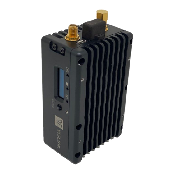
- Page 1 Microlite 3 HD Ultra Compact Wireless Video System Camera Transmission System...
-
Page 2: Conventions
Document Information 1.1. Document Disclaimer The information contained in this manual remains the property of VISLINK and may not be used, disclosed, or reproduced in any other form whatsoever without the prior written permission of VISLINK. VISLINK reserves the right to alter the equipment and specification appertaining to the equipment described in this manual without notification. -
Page 3: Document History
Operators Manual Document History Document History Version Date Modification Firmware Version 6/26/2020 First release of document. M55-ML3-UG, Rev A... -
Page 4: Table Of Contents
Connecting Power ..............................20 Operation ..........................21 Power Up the Microlite 3 ............................21 Using the Local User Interface to Control the Microlite 3 ............22 Power settings from OLED Display ....................... 24 SCAN Feature ................................. 25 Using the Web Page to Control the Microlite 3 .................. 26 Connecting to the Web Page .......................... - Page 5 Figure 3: MLT3 Connectors ..........................18 Figure 4: Power and Serial Lemo Mating Connector ..............19 Figure 5: Powering up Microlite 3 ........................21 Figure 6: Green LED indicators and OLED Display ................22 Figure 7: No Video Input Sensed and RF is on Standby ............... 22 Figure 8: User Interface Wire Frame ......................23...
- Page 6 Figure 20: MLT3 Device Status ........................29 Figure 21 - Microlite 3 Options Menu ......................29 Figure 22 - Microlite 3 Transmitter Settings Page (Tablet View) ........... 30 Figure 23 - Microlite 2 Channel Drop-down Menu ................31 Figure 24 – Microlite 2 Frequency Plans ....................33 Figure 25: MLT3 Connectors ..........................
-
Page 7: Safety Information
RF power may be present. CAUTION: Users are strongly recommended to return any equipment that requires RF servicing to VISLINK. WARNING- GaAs / BeO Hazard: Certain components inside the equipment contain Gallium Arsenide and Beryllium Oxide that are toxic substances. Whilst safe to handle under normal circumstances, individual components must not be cut, broken apart, incinerated, or chemically processed. -
Page 8: Health & Safety
It is important to note that the guidelines adopted differ throughout the world and are from time-to-time re-issued with revised guidelines. For VISLINK use, a maximum power density limit (w) of 1w/m² is to be applied when calculating minimum safe working distances. Appendix A refers. -
Page 9: Maximum Rf Power Density Limits
Operators Manual Safety Information 3.5. Maximum RF Power Density Limits The RF Radiation Power Density limit figure recommended by VISLINK is based upon guideline levels published in: • IEEE standard C95.1 1999 - IEEE Standard for Safety Levels with respect to Human Exposure to Radio Frequency Electromagnetic Fields, 3 kHz to 300 GHz. -
Page 10: Introduction
PoV cameras as well as drone, robitic and mobile solutions. The transmitter features HD/SD-SDI and HDMI inputs with COFDM transmission in a small, lightweight chassis. The Microlite 3 delivers up to 200mW of power in a small package, providing long range, reliable HD video transmission. -
Page 11: Product Description
Product Description Product Description This chapter describes the Microlite 3 features and theory of operation. It also includes a block diagram of the Microlite 3 and a description of the internal circuits. The Microlite 3 is a mini transmitter used for various wireless camera system applications that provides superior wireless transmission over the broad spectrum of camera sizes, platforms and markets. -
Page 12: Power Consumption
Operators Manual Product Description Table 2: MLT3 Frequency Bands, Power and Power Consumption Power Power Out Base Model Number Frequency (GHz) Consumption (mW) Watts 23MLT3-23 2.0 - 2.5 24MLT3-20 2.4-2.483 33MLT3-23 3.1 – 3.5 23/33MLT3-23 2.0-2.5/3.1-3.5 55MLT3-23 5.1- 6.0 23/55MLT3-23 2.0-2.5/5.1 –... -
Page 13: Figure 1: Mlt3 Functional Block Diagram
Operators Manual Product Description The IQ Modulator/RF board generates the carrier frequency, modulates, and amplifies the signal. The detected output from the amplifier is looped back for the ALC circuitry. It also carries both the Wi-Fi and 900 MHz transceivers with an embedded ARM Processor for the transmitters’... -
Page 14: Specifications
Operators Manual Specifications Specifications 6.1. Frequency Bands and RF Performance Power Power Out Base Model Number Frequency (GHz) Consumption (mW) Watts 23MLT3-23 2.0 - 2.5 24MLT3-20 2.4-2.483 33MLT3-23 3.1 – 3.5 23/33MLT3-23 2.0-2.5/3.1-3.5 55MLT3-23 5.1- 6.0 23/55MLT3-23 2.0-2.5/5.1 – 6.0 64MLT3-20 6.4 - 7.1 6.2. -
Page 15: Control
Operators Manual Specifications 6.4. Control Wireless Wi-Fi 2.4GHz ISM Band Android/iOS Web Local OLED/Joystick RS232 with Nucomm Commands 6.5. Wi-Fi Wireless Web page Settings Frequency, Bandwidth Modulation, Camera Status Power, Frequency Battery Run Time Meter Alarms Power Video Battery Temperature overheat 6.6. -
Page 16: Altitude
Operators Manual Specifications 6.8. Altitude Operating 20,000 ft. (6,000 m) Storage 50,000 ft. (15,000 m) 6.9. Physical Characteristics Size 4.21(D)” x 2.25(W)” x 1.51(H)” 107 (D) mm x 57 (W) mm x 38 (H)mm Volume 14.2 cubic inches 2318 cubic centimeters Weight <6.5 ounces (185 grams) M55-ML3-UG, Rev A... -
Page 17: Installation
7.1. Overview This chapter contains steps for installing the Microlite 3 in typical applications where it may be used. Due to the small size and power consumption of the MicroLite 3, it may be used in various applications. MicorLite 3’s low power consumption and small size make it an ideal solution for production and PoV cameras as well as a drone, robotic and mobile solutions. -
Page 18: Ship Kit And Accessories
Line Item Qty per Component Part Part Description Assembly M55-ML3-2L3 MicroLite 3 laminated quick start guide 863-E0053-001-R CABLE MICRO USB B TO STD A 1.5M 940-SCC2-18A-R SCC2-18; MicroLite 3 TX Kit Case 922-B1172-01A Cable, Super Slim High-Speed HDMI Cable M-M (1 foot) 921-B437-01A Cable, 1.0/2.3 DIN to BNC Male, 18";L-2.5CHD, 3G/HD-SDI... -
Page 19: Power Serial Port Connections (Item 5)
Operators Manual Installation Table 3: MLT3 Connectors Reference Name Description Physical Type Placement RF Output/ COFDM Output SMA – Female #1 Top of Unit Telemetry Telemetry SMA – Female #2 Top of Unit Input/output Video In #1 Bottom of unit Video In #2 HDMI HDMI... -
Page 20: Antenna Connection
L-Bracket 7.4.4. Connecting Power The Microlite 3 operating voltage with 6-28VDC. The MLT3 kit includes 2 power cable options: Lemo to D-Tap for connecting to a battery or camera. (Item 8 in the accessory kit) 2. Lemo to the bare tinned wire for application-specific or OEM installation. (Item 9 in the accessory kit. -
Page 21: Operation
Operators Manual Operation Operation This chapter covers operational information of the Microlite 3 and programming of the unit (including preset configuration) via the Web page. 8.1. Power Up the Microlite 3 When the installation or set-up is complete as shown in the installation section, connect the power. -
Page 22: Using The Local User Interface To Control The Microlite 3
Transmitting Figure 6: Green LED indicators and OLED Display Figure 7: No Video Input Sensed and RF is on Standby 8.2. Using the Local User Interface to Control the Microlite 3 The MLT3 local user interface displays the following: •... -
Page 23: Figure 8: User Interface Wire Frame
Operators Manual Operation Figure 8: User Interface Wire Frame Figure 9: Local User Interface M55-ML3-UG, Rev A... -
Page 24: Power Settings From Oled Display
Operators Manual Operation Figure 10 User Interface - Shadowing Shown on Parameters being Changed or Set The Local User Interface consists of an OLED display and a 4-way joystick. To make changes to these features you: 1) Click the center of the joystick to initiate 2) Click joystick Left/Right to outline the parameter you wish to change 3) Click the joystick Up/Down to scroll through values. -
Page 25: Scan Feature
8.2.2. SCAN Feature The scan feature is used by the Microlite 3 to select a non-adjacent, clear frequency channel based on an algorithm. To access this feature, long-press the center of the toggle button. A screen “DFS SCAN” would be displayed. Once the scan is complete, it would display the clear channel number of the OLED screen. -
Page 26: Using The Web Page To Control The Microlite 3
8.3. Using the Web Page to Control the Microlite 3 The Microlite 3 Web page is an intuitive GUI design for ease of use. It is connected over the Wi-Fi signal from the Microlite 3 integrated Wi-Fi antenna. All Microlite 3 parameters may be configured via the Web page. -
Page 27: Home
Operators Manual Operation Figure 17: Webpage Connection via Wi-Fi 8.3.2. Home Page Features • Transmission Mode • Device Status • System information • Alarms (No Video, Overheating, Low Voltage) – this appears as an orange banner across all pages. Figure 18: Home Page (RF Transmission in Standby) M55-ML3-UG, Rev A... -
Page 28: Transmission Mode
Operators Manual Operation 8.3.3. Transmission Mode There are 4 settings for MLT3 Transmissions: • HIGH - In this mode, the transmitter is transmitting on High Power • LOW - Transmits in Low Power • STANDBY - In this mode, the transmitter is OFF, but the power levels are kept up so that it could be turned ON within few seconds. -
Page 29: Figure 20: Mlt3 Device Status
Operators Manual Operation Figure 20: MLT3 Device Status Clicking this icon, on the top right corner of the Web page, opens the Options Menu. Figure 21 - Microlite 3 Options Menu M55-ML3-UG, Rev A... -
Page 30: Tx-Settings Page
Hover over the button to expose the parameters. • Long Range – Decent quality, but longer range. • Manual Modulation – Select constellation, bandwidth, code rate, and guard interval. Figure 22 - Microlite 3 Transmitter Settings Page (Tablet View) M55-ML3-UG, Rev A... -
Page 31: Channel Selection
Operation 8.3.5.2. Channel Selection This displays the current frequency of the Microlite 3 Transmitter along with the channel number. The Microlite 3 features programmable channels. These frequencies can be edited manually in the ‘Frequency Plan’ page. Figure 23 - Microlite 2 Channel Drop-down Menu 8.3.5.3. -
Page 32: Advanced Settings
Click Apply; a “setting saved” banner appears when changes have been saved. 8.3.7. Frequency Plan Page Ten channels may be programmed into the Microlite 3. Current frequencies have the option of editing or deleting, based on its usage for an application. The frequencies are in MHz. -
Page 33: Edit A Frequency
Operators Manual Operation Figure 24 – Microlite 2 Frequency Plans 8.3.7.1. Edit a Frequency On the Frequency Plan page, click the ‘pencil’ icon next to the frequency to be changed. Use the keypad to enter the frequency in MHz; do not use a decimal point. If the frequency is in the wrong format or out of range a warning is displayed. -
Page 34: Telemetry
Key Number. Place the Key Number in the space provided and hit enter. Your product will now be licensed. 8.5. Telemetry The ML3’s telemetry allows you to remote control and camera control using the Vislink Focal point kit and the integrated 920Mhz Telemetry Radio. 8.5.1. -
Page 35: Microlite 3 Connectors
Cable - FCDF to Antenna - LMR-400 10ft USB Stick USB stick with RC application and user guide MLT3-ASSY-2101 Power/Serial Cable - 7 Pin Lemo to Breakout 8.5.2. MicroLite 3 Connectors Figure 25: MLT3 Connectors Table 7: MLT3 Connectors Reference Name Description... -
Page 36: Set-Up
Operators Manual Operation 8.5.3. Set-Up Set the system as shown in the figure below. Note: The ULRX or L2174 must be on the ‘inverted’ spectrum for the video to lock with the MicroLite in LMST. Figure 26: MLT3 RC and CC Typical Set Up with Direct Connect M55-ML3-UG, Rev A... -
Page 37: Operation
1) Connect as shown in Figure 26, Figure 27, or as solution drawing provided by Vislink. 2) Install the Vislink Remote Control (VRC) application onto a laptop from the USB stick. Connect Laptop or Device to the serial input of the FCDT using the Serial Cable and the Rs232 USB-DB9 Dongle. -
Page 38: Figure 28: Adding Microlite To Rc Application
Operators Manual Operation Preprogramed channels Figure 28: Adding MicroLite to RC Application Enter DF name/SN and channel. Press ‘Add’. The laptop must have only one USB port running for the VRC to detect. Figure 29: Adding new Transmitter Getting the status of each transmitter . -
Page 39: Figure 30: Retrieving Mlt3 Status From Rc Application
Operators Manual Operation Press the ‘Control’ button to populate DF status Timeline bar. The DF parameters will load and populate when complete Figure 30: Retrieving MLT3 Status from RC Application 8) Setting a new parameter All parameters may be set by using a button, text box, or dropdown. b. -
Page 40: Figure 31: Applying Parameter Using The Rc Application
Operators Manual Operation Preset Tabs Managed MLT3 RF and Advanced tabs Apply Figure 31: Applying Parameter Using the RC Application Figure 32: Saved Presets 11) Sending commands to multiple transmitters. a. Check all the boxes you want to send the RC command to. b. -
Page 41: Remote Control Application
Operators Manual Operation 8.6. Remote Control Application The remote control application is broken into 4 sections. Tab 1 contains the following sections: 1) Manage Transmitters - DragonFly Connections 2) Parameter Settings 3) Action Keys The 2 tab shows stored presets. Figure 33: Remote Control Tab Sections 8.6.1. -
Page 42: Manage Selected Transmitters
Operators Manual Operation 8.6.2. Manage Selected Transmitters This section contains the remote-control commands for the dragonfly. It features two main tabs: RF Tab – Frequency and Power Advanced Tab – all other parameters. The following parameters may be controlled: Table 8: Remote Control Applications Settings Control Activator Description... -
Page 43: Remote Control
Operators Manual Operation Appendix A Remote Control Commands 8.7. Remote Control 8.7.1. Remote Control Commands Command String Nomenclature Literal <tt> Address of target (0x01 – 0xFF) <ss> Address of source (0x00 – 0xFF) <##> Packet length (Range: Command Length + Data Length) <cc>... - Page 44 Operators Manual Operation Command Command String 10 – Serial port mode 00 – remote control 01 – debug mode 20 – Response upper/lower frequency plan limit in kHz 2.<dd><dd><dd><dd>: upper limit 3.<dd><dd><dd><dd>: lower limit 26 – Response RF detector voltage (in mV) 2.<dd><dd>: RF detector voltage Request Factory NU<tt><ss><02><E0><dd><CS><CR><LF>...
-
Page 45: Usage Examples
Operators Manual Operation 8.7.1.1. Usage Examples Communication Overview To communicate with Nucomm equipment a standard ASCII byte-oriented packet is used over an RS232 link. RS232 settings: BAUD: 9600 (Default) Unit is selectable DATA: 8 STOP: 1 Flow: None Packet outline: <NU><Target address><source address><><Length><command><data>... -
Page 46: Alarm Reporting
Operators Manual Operation Request Serial # NU<01><00><01><F4><09><CR><LF> Send Serial # NU<00><01><09><74><32><31><31><32><2D><59><59><5A>< 82><CR><LF> The serial number is ”t2112-YYZ.” 8.7.2. Alarm Reporting Alarm reporting is handled through 2 commands. One reports a list of 2-byte alarm codes while a second command responds with an English description for specific alarm code. -
Page 47: Figure 34: Clamshell Goldmount Assembly Instruction
Operators Manual Operation Appendix B – Mounting Assembly Instruction Figure 34: Clamshell Goldmount Assembly Instruction M55-ML3-UG, Rev A... -
Page 48: Figure 35: Clamshell V-Clip Assembly Instruction
Operators Manual Operation Figure 35: Clamshell V-Clip Assembly Instruction Figure 36: L-Bracket Goldmount Assembly Instruction M55-ML3-UG, Rev A... - Page 49 Operators Manual Operation This page is intentionally unused. M55-ML3-UG, Rev A...
Need help?
Do you have a question about the Microlite 3 and is the answer not in the manual?
Questions and answers