Table of Contents
Advertisement
Quick Links
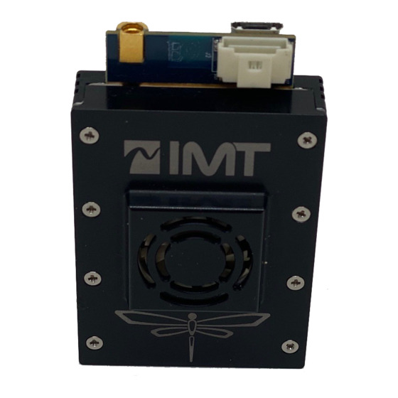
DragonFly
Transmitter
Installation and Integration Guide
Vislink, Waterside House, Earls Colne Business Park, Colchester, Essex, CO6 2NS, UK
Telephone: +44 (0)1442 431300 ● Facsimile: +44 (0) 1494 775356 ● Email: sales@vislink.com ● Website: www.vislink.com
Company Registered in England & Wales no. 10523708 ● VAT registration no. GB 260 012 169
Registered Office: Waterside House, Earls Colne Business Park, Colchester, Essex, CO6 2NS, UK
Advertisement
Table of Contents

Subscribe to Our Youtube Channel
Related Manuals for Vislink DragonFly


Summary of Contents for Vislink DragonFly
- Page 1 Vislink, Waterside House, Earls Colne Business Park, Colchester, Essex, CO6 2NS, UK Telephone: +44 (0)1442 431300 ● Facsimile: +44 (0) 1494 775356 ● Email: sales@vislink.com ● Website: www.vislink.com Company Registered in England & Wales no. 10523708 ● VAT registration no. GB 260 012 169...
- Page 2 Document Disclaimer The information contained in this manual remains the property of Vislink and may not be used, disclosed or reproduced in any other form whatsoever without the prior written permission of Vislink. Vislink reserves the right to alter the equipment and specification appertaining to the equipment described in this manual without notification.
- Page 3 Document History Version Date Modification Author 09/08/2019 First draft Issue No: A Page: iii Ref: DragonFly Installation Guide Copyright © 2020 IMT and Vislink are Vislink Technologies Inc. companies...
-
Page 4: Table Of Contents
3.7.1. Board Outlines ......................... 15 3.7.2. Physical Installation OEM DragonFly Board Model Kit..........18 Table of Figures Figure 3-1: OEM DragonFly Chassis Model Outline Drawing ........... 10 Figure 3-2: Connectors ........................10 Figure 3-3: OEM DF Chase Installation ..................12 Figure 3-4 - Supplied Battery ...................... -
Page 5: General Information
CAUTION: The unit is IPxx rated and must be protected from dripping or splashing water/fluids. When used outdoors, protect the unit using a rain cover. Issue No: A Page: 5 Ref: DragonFly Installation Guide Copyright © 2020 IMT and Vislink are Vislink Technologies Inc. companies... -
Page 6: Health & Safety
It is important to note that the guidelines adopted differ throughout the world and are from time-to-time re-issued with revised guidelines. For Vislink use, when calculating minimum safe working distances, apply a maximum power density limit (w) of 1w/m². Appendix A refers. -
Page 7: Maximum Rf Power Density Limits
Guide DF Integration 1.5. Maximum RF Power Density Limits The RF Radiation Power Density limit figure recommended by Vislink is based upon guideline levels published in: a. IEEE standard C95.1 1999 - IEEE Standard for Safety Levels with respect to Human Exposure to Radio Frequency Electromagnetic Fields, 3 kHz to 300 GHz. -
Page 8: Introduction
70ms, making it well-suited for remote control applications. The DragonFly was designed with a compact size and weight form factor and minimized power requirements, making it ideal for drone use. IMTDragonFly has an HD-SDI input for a high-quality camera interface. -
Page 9: Product Descriptions And Kits
3.2. Chassis Model Installation and Integration Overview This chapter contains steps for installing the DragonFly in typical applications where it may be used. Due to the small size and power consumption of the DragonFly, it may be used in various applications. -
Page 10: Connectors
Guide DF Integration Figure 3-1: OEM DragonFly Chassis Model Outline Drawing 3.4. Connectors Figure 3-2: Connectors Issue No: A Page: 10 Ref: DragonFly Installation Guide Copyright © 2020 IMT and Vislink are Vislink Technologies Inc. companies... -
Page 11: Power And Serial Connector
RS422/485 - plus (HDMI Version) Ground Serial - Remote Control RS232- RX In Serial - Remote Control RS232- TX In Issue No: A Page: 11 Ref: DragonFly Installation Guide Copyright © 2020 IMT and Vislink are Vislink Technologies Inc. companies... -
Page 12: Physical Installation
2) Place the thermal pad to align the through-holes with pattern in the DragonFly. 3) Fasten DragonFly in place using 4 2-56 screws supplied in the kit, or chose to fit. 4) Make or purchase cables need to run DragonFly. The following cable is needed to be made: a. -
Page 13: Oem Board Model Kits
Guide DF Integration Figure 3-4 - Supplied Battery Figure 3-5 – Antenna 3.7. OEM Board Model Kits There are currently 4 OEM DragonFly Board Kits depending on the frequency and video input type. DragonFly OEM 2GHz SDI Line Item Part Number... - Page 14 Cable, 8-P Power Conn to Bare Tinned Leads, 12", Dragonfly 922-B1264-01A-R Cable, 7.4VDC Tenergy Battery to 2-P Molex, 6", Dragonfly V3 922-B1265-01A-R Cable, TLP-2000 7.4VDC LI-Ion Charger with 2-P Molex, 6", Dragonfly V3 Cable,USB2.0 Micro Conn Cable, 0.5 Meter USB B Micro Male USB A 922-B1133-01A-R Male...
-
Page 15: Board Outlines
Cable, 8-P Power Conn to Bare Tinned Leads, 12", Dragonfly 922-B1264-01A-R Cable, 7.4VDC Tenergy Battery to 2-P Molex, 6", Dragonfly V3 922-B1265-01A-R Cable, TLP-2000 7.4VDC LI-Ion Charger with 2-P Molex, 6", Dragonfly V3 Cable,USB2.0 Micro Conn Cable, 0.5 Meter USB B Micro Male USB A 922-B1133-01A-R Male... -
Page 16: Figure 3-6: Encoder Board Top View
Guide DF Integration Figure 3-6: Encoder Board Top View Figure 3-7: Encoder Board Bottom View Figure 3-8: RF Board Top View Issue No: A Page: 16 Ref: DragonFly Installation Guide Copyright © 2020 IMT and Vislink are Vislink Technologies Inc. companies... -
Page 17: Figure 3-9: Rf Board Bottom View - Pink Denotes Rf Isolation
Guide DF Integration Figure 3-9: RF Board Bottom View - Pink Denotes RF Isolation Figure 3-10: Board Placement Cavity Issue No: A Page: 17 Ref: DragonFly Installation Guide Copyright © 2020 IMT and Vislink are Vislink Technologies Inc. companies... -
Page 18: Physical Installation Oem Dragonfly Board Model Kit
The Board model should be used only when the DragonFly needed to be embedded in the system because of space or when there is no other choice. There are two main reasons for this: 1) The RF sections must be isolated from each other for the unit to work correctly. - Page 19 Antenna extension cable – purchased or made. Issue No: A Page: 19 Ref: DragonFly Installation Guide Copyright © 2020 IMT and Vislink are Vislink Technologies Inc. companies...
- Page 20 Guide DF Integration Figure 3-11: DF Installation Diagram Issue No: A Page: 20 Ref: DragonFly Installation Guide Copyright © 2020 IMT and Vislink are Vislink Technologies Inc. companies...
- Page 21 Guide DF Integration Issue No: A Page: 21 Ref: DragonFly Installation Guide Copyright © 2020 IMT and Vislink are Vislink Technologies Inc. companies...
- Page 22 Guide DF Integration Issue No: A Page: 22 Ref: DragonFly Installation Guide Copyright © 2020 IMT and Vislink are Vislink Technologies Inc. companies...
Need help?
Do you have a question about the DragonFly and is the answer not in the manual?
Questions and answers