Sign In
Upload
Manuals
Brands
Vislink Manuals
Extender
Microlite 3
User Manuals: Vislink Microlite 3 Video Transmitter
Manuals and User Guides for Vislink Microlite 3 Video Transmitter. We have
1
Vislink Microlite 3 Video Transmitter manual available for free PDF download: Operator's Manual
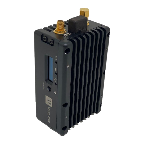
Vislink Microlite 3 Operator's Manual (49 pages)
HD Ultra Compact Wireless Video System Camera Transmission System
Brand:
Vislink
| Category:
Extender
| Size: 2 MB
Table of Contents
Conventions
2
Service/Support Contacts
2
Document History
3
Table of Contents
4
Safety Information
7
General Information
7
Disposal Instructions
7
Environmental
7
Health & Safety
8
Maximum RF Power Density Limits
9
Introduction
10
Product Description
11
Features and Benefit
11
Frequency Bands and Power
11
Table 1: Features and Benefits
11
Power Consumption
12
Wi-Fi Controller
12
Transmitter Electrical Description
12
Table 2: MLT3 Frequency Bands, Power and Power Consumption
12
Figure 1: MLT3 Functional Block Diagram
13
Specifications
14
Frequency Bands and RF Performance
14
Modulation Modes
14
MPEG Encoder
14
Control
15
Wi-Fi Wireless Web Page
15
Power Requirements
15
Environmental
15
Altitude
16
Physical Characteristics
16
Installation
17
Overview
17
Physical Description
17
Outline Drawing
17
Figure 2: Outline Drawing
17
Ship Kit and Accessories
18
Physical Installation
18
Connectors
18
Figure 3: MLT3 Connectors
18
Power Serial Port Connections (Item 5)
19
Figure 4: Power and Serial Lemo Mating Connector
19
Table 3: MLT3 Connectors
19
Antenna Connection
20
Connecting Power
20
Table 4: Power/Serial Connector Pinout
20
Operation
21
Power up the Microlite 3
21
Figure 5: Powering up Microlite 3
21
Using the Local User Interface to Control the Microlite 3
22
Figure 6: Green LED Indicators and OLED Display
22
Figure 7: no Video Input Sensed and RF Is on Standby
22
Figure 8: User Interface Wire Frame
23
Figure 9: Local User Interface
23
Power Settings from OLED Display
24
Figure 10 User Interface - Shadowing Shown on Parameters Being Changed or Set
24
Figure 11: Joystick for Control
24
SCAN Feature
25
Figure 12: HI, LO, STB Power Setting on the OLED Display
25
Figure 13: Last Power Setting
25
Figure 14: Microlite 3 Rebooting from Hibernate
25
Using the Web Page to Control the Microlite 3
26
Connecting to the Web Page
26
Figure 15: DFS Scan Feature
26
Figure 16: Clear Channel Number Is Displayed on the Screen
26
Home
27
Figure 17: Webpage Connection Via Wi-Fi
27
Figure 18: Home Page (RF Transmission in Standby)
27
Transmission Mode
28
Device Status
28
Figure 19: Power Modes
28
Figure 20: MLT3 Device Status
29
Figure 21 - Microlite 3 Options Menu
29
TX-Settings Page
30
Transmit Settings
30
Figure 22 - Microlite 3 Transmitter Settings Page (Tablet View)
30
Channel Selection
31
Modulation Selection
31
Manual Settings
31
Figure 23 - Microlite 2 Channel Drop-Down Menu
31
Advanced Settings
32
Baud Rate
32
Telemetry
32
Encryption (Optional)
32
Frequency Plan Page
32
Edit a Frequency
33
Adding a New Frequency to the List
33
Unit Info Page
33
Figure 24 - Microlite 2 Frequency Plans
33
Telemetry
34
Equipment Required
34
Table 5: Focal Point Telemetry Radio Selection
34
Microlite 3 Connectors
35
Figure 25: MLT3 Connectors
35
Table 6: MLT3 Camera Control Kit
35
Table 7: MLT3 Connectors
35
Set-Up
36
Figure 26: MLT3 RC and CC Typical Set up with Direct Connect
36
Operation
37
Figure 27: MLT3 Camera Control with Fiber Extension
37
Figure 28: Adding Microlite to RC Application
38
Figure 29: Adding New Transmitter
38
Figure 30: Retrieving MLT3 Status from RC Application
39
Figure 31: Applying Parameter Using the RC Application
40
Figure 32: Saved Presets
40
Remote Control Application
41
Manage Transmitters
41
Figure 33: Remote Control Tab Sections
41
Manage Selected Transmitters
42
Remote Control Action Keys
42
Table 8: Remote Control Applications Settings
42
Remote Control
43
Remote Control Commands
43
Usage Examples
45
Example 1 - to Request Unit Model Number
45
Example 2 - to Request Unit Serial Number
45
Alarm Reporting
46
Alarm Example
46
Figure 34: Clamshell Goldmount Assembly Instruction
47
Figure 35: Clamshell V-Clip Assembly Instruction
48
Figure 36: L-Bracket Goldmount Assembly Instruction
48
Advertisement
Advertisement
Related Products
Vislink HDT-1000
Vislink HDT-1000S2
Vislink HDX-1100C1
Vislink HDX-1100C2
Vislink HDX-1100C3
Vislink HDX-1100LS
Vislink HDX-1100S
Vislink HDX-1100X
Vislink NewStream
Vislink Categories
Receiver
Media Converter
Extender
Transmitter
Amplifier
More Vislink Manuals
Login
Sign In
OR
Sign in with Facebook
Sign in with Google
Upload manual
Upload from disk
Upload from URL