Table of Contents
Advertisement
Quick Links
Advertisement
Table of Contents

Related Manuals for DFI EC500-SD


Summary of Contents for DFI EC500-SD
- Page 1 EC500-SD User’s Manual A45100703 Chapter 1 Introduction www.dfi.com...
-
Page 2: Copyright
Product names or trademarks appearing in this manual are for identification purpose only and Shielded interface cables must be used in order to comply with the emission limits. are the properties of the respective owners. Chapter 1 Introduction www.dfi.com... -
Page 3: Table Of Contents
S/PDIF Connector ..........................30 Specifications ......................7 LPC Connector ............................30 Expansion Slots ............................31 Getting to Know the EC500-SD ................8 12V DC-out ............................... 32 Chapter 6 - Mounting Options ..........33 Mechanical Dimensions ..................9 Chapter 2 - Getting Started ............10 Chapter 7 - BIOS Setup ...............34... -
Page 4: About This Manual
After installation or servicing, cover the system chassis before plugging the power cord. Battery: • Danger of explosion if battery incorrectly replaced. • Replace only with the same or equivalent type recommend by the manufacturer. • Dispose of used batteries according to local ordinance. Chapter 1 Introduction www.dfi.com... -
Page 5: Safety Precautions
• Unplug the power cord before removing the system chassis cover for installation or servic- ing. After installation or servicing, cover the system chassis before plugging the power cord. • 1 EC500-SD system unit • 1 CD disk includes: Drivers/Manual •... -
Page 6: Chapter 1 - Introduction
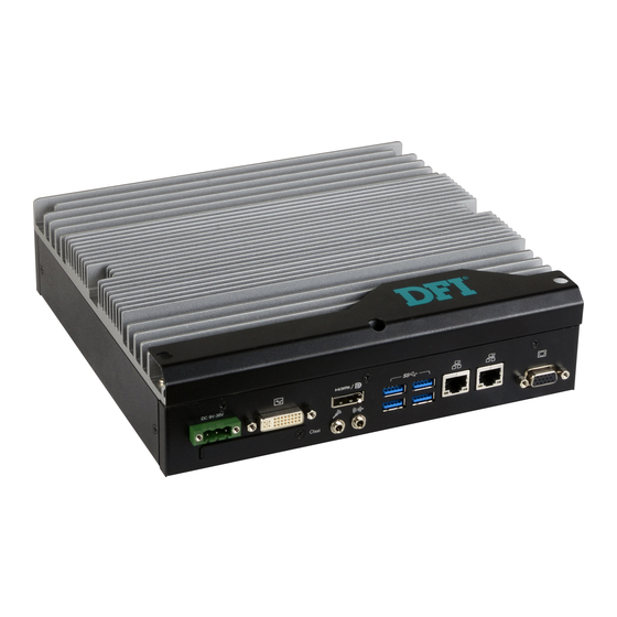
Chapter 1 Chapter 1 - Introduction Key Features Overview Model Name EC500-SD ® Processor 6th Generation Intel Core processors Chipset ® Intel Q170 Chipset 2 LAN ports 4 COM ports Audio Line-out and microphone jack Display DVI (DVI-D signal) HDMI or DP (DP available upon request) Front View 2 USB 2.0 Type A ports, 4 USB 3.0 Type A ports... -
Page 7: Specifications
• Windows 10 Other Features System Reset, Programmable via Software from 1 to 255 Seconds Standards and IEC68-2-64 Certifications Note: * Optional and is not supported in standard model. Please contact your sales repre- sentative for more information. Chapter 1 Introduction www.dfi.com... -
Page 8: Getting To Know The Ec500-Sd
Chapter 1 Getting to Know the EC500-SD Front View Rear View Power Button DVI-I DC-in (DVI-D Signal) Status LED USB 3.0 HDMI HDD LED USB 2.0 COM 4 COM 2 COM 1 COM 3 Remote power CFast Microphone LAN 1... -
Page 9: Mechanical Dimensions
Chapter 1 Mechanical Dimensions Chassis Dimensions Motherboard Dimensions Front View 209.55 Gold finger PCIE X4 Gold finger PCIE X16 mini PCIe 60.70 60.70 Left View Right View Rear View Chapter 1 Introduction www.dfi.com... -
Page 10: Chapter 2 - Getting Started
Installing the Drivers The system package includes a CD disk. The CD includes drivers that must be installed to pro- vide the best system performance. Refer to the Supported Software chapter for instructions on installing the drivers. Chapter 2 Getting Started www.dfi.com... -
Page 11: Chapter 3 - Installing The Devices
Remove these screws and put them in a safe place for later use. Mounting Screw The SODIMM sockets, Mini PCIe slot and SATA drive bay are accessible after removing the chassis cover. SATA drive bay Mini PCIe slot Mounting Screw SODIMM socket Chapter 3 Installing the Devices www.dfi.com... -
Page 12: Installing A Sodimm
SATA drive bay Notes: The system supports dual-channel configuration. To enable dual-channel, populate both SODIMM sockets. SODIMM socket The SODIMM sockets can only accept DDR4 memory modules. Please do not install other types of memory modules. Chapter 3 Installing the Devices www.dfi.com... -
Page 13: Installing A 2.5" Sata Drive
Place the SATA drive installed with the HDD bracket in the system. Align the mounting holes on the HDD bracket with the mounting holes on the drive bay and use the provided mounting screws to secure the drive in place. Mounting Screws Mounting hole Chapter 3 Installing the Devices www.dfi.com... -
Page 14: Installing A Cfast Card
Push the Mini PCIe card down and use the provided mounting screw to secure the card on the system board. Close the CFast card cover. To eject the card, push the card inward to release the lock and pull it out. Mounting screw Chapter 3 Installing the Devices www.dfi.com... - Page 15 The bottom side of a full-size Mini PCIe module should have a component height restriction of 0.82 mm and will sit flush against the connected half-size Mini PCIe module if such a component is used and the half-size slot is connected with a module. 0.82mm Chapter 3 Installing the Devices www.dfi.com...
-
Page 16: Installing A Cpu
LGA 1151 socket comes with the protective cap. 5. Unlock the socket by pushing the load lever down, move it sideways until it is released from the retention tab, and then lift the load lever up. Alignment key Gold triangular mark Chapter 3 Installing the Devices www.dfi.com... - Page 17 10. Close the load plate and push the load lever down to lock it under the retention tab. While closing the load plate, slide the front edge of the load plate under the retention tab. Retention knob Chapter 3 Installing the Devices www.dfi.com...
-
Page 18: Chapter 4 - Jumper Settings
2. Set the jumper pins 2 and 3 to On. Wait for a few seconds and set the jumper back to its default setting: 1-2 On. 3. Now plug the power cord and power on the system. Chapter 4 Jumper Settings www.dfi.com... -
Page 19: Com1/Com2 Rs232 Power Select
JP3 (for COM1) and JP2 (for COM2) are used to configure serial COM ports to normal RS232 or RS232 with power. The pin assignments (Pin 1: optional 12V and Pin 9: optional 5V) of COM1 and COM2 will vary according to JP3’s and JP2’s setting respectively. Chapter 4 Jumper Settings www.dfi.com... -
Page 20: Com1/Com2 Rs232/422/485 Select
BIOS setup utility. For more information, refer to Chapter 7. Note: When COM1 RS232/422/485 is selected, JP5 and JP12 must be set in accordance to JP6. And when COM2 RS232/422/485 is selected, JP7 and JP14 must be set in accor- dance to JP13. Chapter 4 Jumper Settings www.dfi.com... -
Page 21: Com3/Com4 Rs232/422/485 Select
When COM3 RS232/422/485 is selected, JP8 and JP15 must be set in accordance to 3-5, 4-6 On: 1-3, 2-4 On: JP9. And when COM4 RS232/422/485 is selected, JP10 and JP16 must be set in ac- RS422 Full Duplex/RS485 RS232 (default) cordance to JP4. Chapter 4 Jumper Settings www.dfi.com... -
Page 22: Chapter 5 - Ports And Connectors
3 USB 2.0 ports through the internal pin headers. • BIOS Setting Configure the onboard USB in the Advanced menu (“USB Configuration” submenu) of the BIOS. Refer to Chapter 7 for more information. Chapter 5 Ports and Connectors www.dfi.com... -
Page 23: Com (Serial) Ports
Configure the serial ports in the Advanced menu (“Super IO Configuration” submenu) of the BIOS. You can use the BIOS setup utility to configure RS485 auto flow mechanism. Refer to Chapter 7 for more information. Chapter 5 Ports and Connectors www.dfi.com... -
Page 24: Rj45 Lan Ports
Configure the display devices in the Advanced menu (“Video Configuration” submenu) of the BIOS. Refer to the Chapter 7 for more information. Driver Installation Install the graphics driver. Refer to Chapter 8 for more information. Chapter 5 Ports and Connectors www.dfi.com... -
Page 25: Usb Ports
3.0 can transfer data up to 5 Gbps whereas the USB 2.0 can transfer data up to 480Mbps. • BIOS Setting Configure the onboard USB in the Advanced menu (“USB Configuration” submenu) of the BIOS. Refer to Chapter 7 for more information. Chapter 5 Ports and Connectors www.dfi.com... -
Page 26: Rear Audio Connectors
Install the audio driver. Refer to the Chapter 8 for more information. mode and at a speed faster than the SPP’s data (Extended Capabilities Port) transfer rate. Allows bidirectional parallel port operation at the maximum speed. (Enhanced Parallel Port) Chapter 5 Ports and Connectors www.dfi.com... -
Page 27: Front Panel Connector
LED Power Configure the Serial ATA drives in the Advanced submenu (“SATA Configuration” section) of the Ground Signal BIOS. Refer to Chapter 7 for more information. RST Signal Ground RESET SW ATX-SW N.C. Signal Chapter 5 Ports and Connectors www.dfi.com... -
Page 28: Sata (Serial Ata) Power Connectors
SATA power connector and the other end to your storage device. multiple device bus that allows multiple chips to connect to the same bus and enable each one to act as a master by initiating data transfer. Chapter 5 Ports and Connectors www.dfi.com... -
Page 29: Cooling Fan Connectors
The Super IO menu (“PC Health Status” submenu) of the BIOS will display the current speed DIO7 of the cooling fans. Refer to Chapter 7 for more information. DIO6 DIO5 DIO4 DIO3 DIO2 DIO1 DIO0 Chapter 5 Ports and Connectors www.dfi.com... -
Page 30: S/Pdif Connector
24MHz LPC bus clock. For more information about LPC bus refer to the Intel ® Pin Count Interface Specification Revision 1.1’. The table below indicates the pin assignments of the LPC connector. Pin Assignment Pin Assignment L_CLK L_AD1 L_RST# L_AD0 L_FRAME# L_AD3 L_AD2 INT_SERIRQ 5VSB Chapter 5 Ports and Connectors www.dfi.com... -
Page 31: Expansion Slots
Insert a CFast card into this slot. Please refer to Chapter 3 for installation procedure. Note that DPB_CTRL_CLK LPC_AD1 CFast cards are not physically or electrically compatible with CompactFlash cards. DPB_CTRL_DATA LPC_AD2 DPC_CTRL_CLK LPC_AD3 DPC_CTRL_DATA LPC_LDRQ1# Reserved DPC_HPD Chapter 5 Ports and Connectors www.dfi.com... -
Page 32: Dc-Out
4-pin power GND2 PCIE_ECX_TX3n SATA_TXp PCIE_ECX_TX3p Reserved DC-in PCIe x16 (PCIE1) PCIe x4 (PCIE2) SMB_CLK_RESUME DFI Board ID_0 SMB_DATA_RESUME DFI Board ID_1 The 4-pin vertical type connector (optional) provides low power output. INT_GPIO# DFI Board ID_2 PCIe_Wake# SATA_RXn INT_SERIRQ SATA_RXp +3.3VDU... -
Page 33: Chapter 6 - Mounting Options
2 Wall mount brackets Mounting screw • 4 Bracket screws Wall mount Wall mount bracket bracket 1. The wall mounting holes are located on the bottom of the system unit. Ø8.50 Mounting hole Ø3.60 251.80 262.80 Chapter 6 Mounting Options www.dfi.com... -
Page 34: Chapter 7 - Bios Setup
“Reset” button. You may also additional options are available for that field. To display the submenu, move the highlight to restart the system by pressing the <Ctrl> <Alt> and <Del> keys simultaneously. that field and press <Enter>. Chapter 4 BIOS Setup www.dfi.com... -
Page 35: Main
The time format is <hour>, <minute>, <second>. The time is based on the 24-hour military-time clock. For example, 1 p.m. is 13:00:00. Hour displays hours from 00 to 23. Minute displays minutes from 00 to 59. Second displays seconds from 00 to 59. Chapter 4 BIOS Setup www.dfi.com... - Page 36 Wake on RTC Automatically power the system on at a particular time every day from the Real-time clock battery. Specify the wake up time of the day below: <hour> (00~23), <minute> (00~59), <second> (00~59). Chapter 4 BIOS Setup www.dfi.com...
- Page 37 Set the display device combination during system booting. Note that this option only appears when the boot type selected is dual and legacy boot type. Internal Graphics Enable, disable or to automatically detect internal graphics. Always Enabled PEG Enable or disable the PCIe graphics function. Chapter 4 BIOS Setup www.dfi.com...
- Page 38 RST) on the Serial ATA devices. Serial ATA Port 0, 1 and 2 Enable or disable each serial ATA port: SATA Port 0 controls SATA3_0 SATA Port 1 controls SATA3_1 SATA Port 2 controls the half-size Mini PCIe slot Chapter 4 BIOS Setup www.dfi.com...
- Page 39 PCIe Root Port 6 controls LAN 2 PCIe Root Port 7 controls the full-size Mini PCIe slot PCIe Root Port 8 controls PCIE2 (x4) connector PCIe Speed Select the speed of the PCI Express Root Port: Auto, Gen1, Gen2 or Gen3. Chapter 4 BIOS Setup www.dfi.com...
- Page 40 Enable or disable flashing of the Intel ME region. Enable or disable Intel Active Management Technology BIOS extension. ® ® Un-Configure ME Clears all ME related configurations without requiring a password on the next boot. Chapter 4 BIOS Setup www.dfi.com...
- Page 41 The range of the temperature is from 0 to 127 Enable Enable the serial port. Fan Speed Count 1 to Fan Speed Count 4 Set the fan speed. The range is from 0 (fan stop)-100% (full speed). Chapter 4 BIOS Setup www.dfi.com...
- Page 42 Set the AC power loss to Always off or Always on. When it is set to Always off, the system’s status will be power-off after an AC power loss event. When it is set to Al- ways on, the system’s status will be power-on after an AC power loss event. Chapter 4 BIOS Setup www.dfi.com...
-
Page 43: Security
Set the administrative password. The length of the password must be greater than one character and less than or equal to 10 characters. Depending on the state of power-on password selected, the supervisor password may be required upon POST or when entering the BIOS setup utility. Chapter 4 BIOS Setup www.dfi.com... -
Page 44: Boot
Enable or disable booting to USB boot devices. Note: If the boot type is set to UEFI, the method for RAID volume creation will be different. Please refer to Chapter 9 ̵ - RAID for more information. Chapter 4 BIOS Setup www.dfi.com... - Page 45 For the advanced menu type: Use + and - keys to arrange the priority of the detected boot devices. For normal menu type: Select the "Boot Type Order" or "Hard Disk Drive" or "USB" category to view and arrange the order of the listed devices. Chapter 4 BIOS Setup www.dfi.com...
-
Page 46: Exit
Select this field and then press <Enter> to exit the BIOS setup and save your changes. Load Optimal Defaults Select this field and then press <Enter> to load optimal defaults. Discard Changes Select this field and then press <Enter> to exit the BIOS setup without saving your changes. Chapter 4 BIOS Setup www.dfi.com... - Page 47 Copyright(c) 2012 - 2016, Insyde Software Corp. All Rights Reserved. Initializing Current BIOS Model name: SD263 New BIOS Model name: SD263 Current BIOS version: 65.05A New BIOS version: 65.05A Updating Block at FFFFF000h 100% 100% C:\SD263>_ Chapter 4 BIOS Setup www.dfi.com...
-
Page 48: Chapter 8 - Supported Software
Insert the DVD into a DVD-ROM drive. The auto-run screen will appear. If the “Autorun” does not automatically start, please go directly to the root directory of the DVD and double-click “Setup”. For Windows 10 Chapter 8 Supported Software www.dfi.com... - Page 49 To install the utility, click “Intel Chipset Software Installation Utility” on the main menu. 1. Setup is ready to install the utility. Click “Next” to continue. 2. Read the license agreement and then click “Yes”. Chapter 8 Supported Software www.dfi.com...
- Page 50 1 to 2 minutes (while WinSAT is running) before the Windows 7/Windows 8.1/Windows 10 desktop appears. The “blank screen” period is the time Windows is testing the graphics performance. 2. Read the license agreement and then click “Yes”. Chapter 8 Supported Software www.dfi.com...
- Page 51 Restarting the system will allow the new software installation to take effect. 5. Click “Yes, I want to restart this computer now” and then click “Finish”. Restarting the system will allow the new software installation to take effect. Chapter 8 Supported Software www.dfi.com...
- Page 52 “I accept the terms in the license agreement” if you agree the terms in the agree- ment, and then click “Next”. 3. Select the program features you want to install and then click “Next”. Chapter 8 Supported Software www.dfi.com...
- Page 53 To install the driver, click “Kernel Mode Driver Framework” on the main menu. 1. Click “Yes“ to install the update. 2. The update is being in- stalled now. Chapter 8 Supported Software www.dfi.com...
- Page 54 “I accept the terms in the license agreement” if you agree with the terms in the agreement, and then click “Next”. 5. After the installation is complete, click “Finish” to exit setup. Chapter 8 Supported Software www.dfi.com...
- Page 55 1. Setup is ready to install the driver. 4. The wizard is ready to start the installation. Click “Install”. 2. Click “Next” to continue. 5. Please wait while the program features are being installed. Chapter 8 Supported Software www.dfi.com...
- Page 56 The screenshot displayed above is for illustrative purpose only, and may not resemble the actual screen. The EC500-SD Utility features the following tabs: Information, HW Health, HW Health Set, Watchdog, and DIO. Click on the tabs to access each function.
- Page 57 4. Setup is currently installing the driver. After the installation is complete, click “Next”. 2. Read the license agreement and then click “Yes” if you agree with the terms in the agreement. 5. After the installation is complete, click “Finish”. Chapter 8 Supported Software www.dfi.com...
- Page 58 Click “Next” to begin the installa- tion. 2. Read the license agreement care- fully. Click “I accept the terms in the License Agreement” if you agree with the terms in the agreement and then click “Next”. Chapter 8 Supported Software www.dfi.com...
- Page 59 6. Click “Finish” to exit setup. 2. Read the license agreement care- fully. Click “I have read and accept the terms of the License Agree ment” if you agree with the terms in the agreement and then click “Next”. Chapter 8 Supported Software www.dfi.com...
- Page 60 Please exit all programs before continuing with the installation. 4. Click “Finish” to exit setup. 2. Read the license agreement carefully, accept the terms of the License Agreement, then click “Next” to continue. Chapter 8 Supported Software www.dfi.com...
- Page 61 3. Click “I accept the terms in the click “Finish.” license agreement” if agree with the terms in the agreement and Restarting the system will then click “Next”. allow the new software installation to take effect. Chapter 8 Supported Software www.dfi.com...
- Page 62 Click “Install”. 5. Select the setup type and then 8. The setup program is currently click “Next”. installing the Microsoft Visual C++ package. 9. Click “Finish” to exit setup. 6. Click “Install” to start the installation. Chapter 8 Supported Software www.dfi.com...
- Page 63 To install the reader, click “Adobe Acrobat Reader 9.3” on the main menu. 1. Click Next to install or click Change Destination Folder to select another folder. 2. Click “Install” to begin instal- lation. 3. Click “Finish” to exit setup. Chapter 8 Supported Software www.dfi.com...
-
Page 64: Chapter 9 - Raid
2. Go to “Advanced” menu, and select the “SATA Configuration” menu. 3. Change the “SATA Mode Selection” to “RAID” mode. 4. Save the changes in the “Save & Exit” menu. Chapter 5 RAID 5. Reboot the system. Chapter 9 RAID www.dfi.com... - Page 65 6. Press <Enter>. 7. Use the up or down arrow keys to select the strip size and press <Enter>. 8. Enter the volume size and press <Enter>. 9. At the prompt, press <Y> to confirm volume creation. Chapter 9 RAID www.dfi.com...
- Page 66 4. Read the license agree- ment and click “I accept the terms in the License Agreement.“ Then, click Next. Chapter 5 RAID 7. Confirm the installation and click Next. Chapter 9 RAID www.dfi.com...
- Page 67 Chapter 9 Chapter 5 8. Click “Yes, I want to restart this computer now” to complete the installation and then click Finish. Chapter 5 RAID Chapter 9 RAID www.dfi.com...
-
Page 68: Chapter 10 - Intel Amt Settings
It protects the network from threats at the source by proactively blocking incoming threats, reactively containing infected clients before they impact the network, and proactively alerting when critical software agents are removed. 3. In the “Active Management Technology Support” menu, select “Enabled” for “Intel AMT Support”. Chapter 10 Intel AMT Settings www.dfi.com... - Page 69 Copyright(C) 2003-15 Intel Corporation. All Rights Reserved. MAIN MENU MEBx Login > Intel (R) ME General Settings > Intel (R) AMT Configuration MEBx Exit Intel(R) ME Password [↑↓] = Move Highlight [Enter] = Select Entry [Esc]= Exit Chapter 10 Intel AMT Settings www.dfi.com...
- Page 70 Intel(R) Management Engine BIOS Extension v11.0.0.0005/Intel(R) ME v11.0.0.1205 Copyright(C) 2003-15 Intel Corporation. All Rights Reserved. MAIN MENU > Intel (R) ME General Settings > Intel (R) AMT Configuration MEBx Exit [↑↓] = Move Highlight [Enter] = Select Entry [Esc]= Exit Chapter 10 Intel AMT Settings www.dfi.com...
- Page 71 > User Consent Password Policy <Anytime> > Network Setup Activate Network Access Unconfigure Network Access <Full Unprovision> > Remote Setup And Configuration > Power Control [↑↓] = Move Highlight [Enter] = Select Entry [Esc]= Exit Chapter 10 Intel AMT Settings www.dfi.com...
- Page 72 <Full Unprovi- Disabled sion> Enabled > Remote Setup And Configuration > Power Control [↑↓] = Move Highlight [Enter] = Select Entry [Esc]= Exit [↑↓] = Move Highlight [Enter] = Complete Entry [Esc]= Discard Changes Chapter 10 Intel AMT Settings www.dfi.com...
- Page 73 < Enabled> Storage Redirection <Enabled> KVM Feature Selection <Enabled> NONE Disabled Enabled [↑↓] = Move Highlight [Enter] = Complete Entry [Esc]= Discard Changes [↑↓] = Move Highlight [Enter] = Complete Entry [Esc]= Discard Changes Chapter 10 Intel AMT Settings www.dfi.com...
- Page 74 > Remote Setup And Configuration > Power Control Default Password Only During Stepup And Configuration Anytime [↑↓] = Move Highlight [Enter] = Select Entry [Esc]= Exit [↑↓] = Move Highlight [Enter] = Complete Entry [Esc]= Discard Changes Chapter 10 Intel AMT Settings www.dfi.com...
- Page 75 Shared/ Dedicated FQDN <Shared> Dynamic DNS Update <Disabled> Dynamic DNS Update <Disabled> Computer Domain Name Disabled Enabled [Enter] = Complete Entry [Esc]= Discard Changes [↑↓] = Move Highlight [Enter] = Complete Entry [Esc]= Discard Changes Chapter 10 Intel AMT Settings www.dfi.com...
- Page 76 Unconfigure Network Access > Remote Setup And Configuration Full Unprovision > Power Control [↑↓] = Move Highlight [Enter] = Complete Entry [Esc]= Discard Changes [↑↓] = Move Highlight [Enter] = Complete Entry [Esc]= Discard Changes Chapter 10 Intel AMT Settings www.dfi.com...
- Page 77 > RCFG > TLS PKI > TLS PKI Provisioning Mode: PKI Provisioning server address [↑↓] = Move Highlight [Enter] = Select Entry [Esc]= Exit [↑↓] = Move Highlight [Enter] = Select Entry [Esc]= Exit Chapter 10 Intel AMT Settings www.dfi.com...
- Page 78 PKI DNS Suffix > Manage Hashes This will activate Remote Condigura- tion. Continue: (Y/N) Disabled Enabled [↑↓] = Move Highlight [Enter] = Select Entry [Esc]= Exit [↑↓] = Move Highlight [Enter] = Select Entry [Esc]= Exit Chapter 10 Intel AMT Settings www.dfi.com...
- Page 79 Activate Network Access Unconfigure Network Access <Full Unprovision> > Remote Setup And Configuration > Power Control [↑↓] = Move Highlight [Enter] = Select Entry [Esc]= Exit [↑↓] = Move Highlight [Enter] = Select Entry [Esc]= Exit Chapter 10 Intel AMT Settings www.dfi.com...
- Page 80 This configurations are effective only after AMT provisioning has started Intel (R) ME ON in Host Sleep States <Mobile: ON in S0, ME Wake in S3, S4-5 (AC only)> Idle Timeout 65535 Timeout Value (1-65535) 65535 <ENTER> = Complete Entry [ESC]= Discard Changes Chapter 10 Intel AMT Settings www.dfi.com...
- Page 81 4. There is not enough space left on the diskette. Use another diskette with adequate storage 4. Adjust the brightness of the display by turning the monitor’s brightness control knob. space. Appendix A Troubleshooting Checklist www.dfi.com...
- Page 82 Nothing happens when a key on the keyboard was pressed. 1. Make sure the keyboard is properly connected. 2. Make sure there are no objects resting on the keyboard and that no keys are pressed dur- ing the booting process. Appendix A Troubleshooting Checklist www.dfi.com...
Need help?
Do you have a question about the EC500-SD and is the answer not in the manual?
Questions and answers