Table of Contents
Advertisement
Quick Links
Instructions – Parts List
Parts
CARBON STEEL
Dura–Flot 2400 Pumps
With Severe–Duty Rod and Cylinder
Read warnings and instructions.
See page 2 for model numbers and maximum
working pressures.
GRACO INC. P.O. BOX 1441 MINNEAPOLIS, MN 55440-1441
Copyright 2002, Graco Inc. is registered to I.S. EN ISO 9001
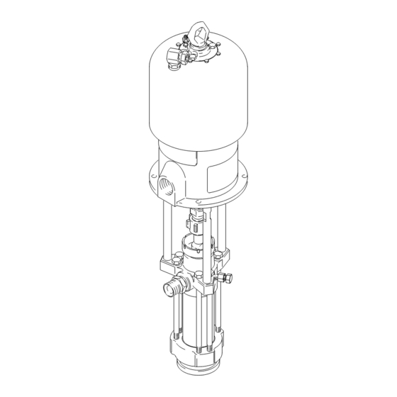
Part No. 222832 Shown
308151M
0566
Advertisement
Table of Contents

Subscribe to Our Youtube Channel
Related Manuals for Graco 222832


Summary of Contents for Graco 222832
- Page 1 With Severe–Duty Rod and Cylinder Read warnings and instructions. See page 2 for model numbers and maximum working pressures. Part No. 222832 Shown 0566 GRACO INC. P.O. BOX 1441 MINNEAPOLIS, MN 55440-1441 Copyright 2002, Graco Inc. is registered to I.S. EN ISO 9001...
-
Page 2: Table Of Contents
Input Pressure 222826, Bulldogr 222801 10:1 7.0 MPa, 69 bar 0.7 MPa, 7 bar Series A (1000 psi) (100 psi) 222832, Kingt 222801 20:1 13.8 MPa, 138 bar 0.7 MPa, 7 bar Series A (2000 psi) (100 psi) 222833, Quiet Kingt... -
Page 3: Warnings
D This equipment is for professional use only. D Read all instruction manuals, tags, and labels before operating the equipment. D Use the equipment only for its intended purpose. If you are uncertain about usage, call your Graco distributor. D Do not alter or modify this equipment. Use only genuine Graco parts and accessories. - Page 4 Permanently coupled hoses cannot be repaired; replace the entire hose. D Use only Graco approved hoses. Do not remove any spring guard that is used to help protect the hose from rupture caused by kinks or bends near the couplings.
- Page 5 WARNING FIRE AND EXPLOSION HAZARD Improper grounding, poor ventilation, open flames or sparks can cause a hazardous condition and result in a fire or explosion and serious injury. D Ground the equipment and the object being sprayed. Refer to Grounding on page 7. D If there is any static sparking or you feel an electric shock while using this equipment, stop spray- ing immediately.
- Page 6 Notes 308151...
-
Page 7: Installation
Installation Grounding 5. Fluid supply container: according to your local code. WARNING 6. Object being sprayed: according to your local code. FIRE AND EXPLOSION HAZARD Before operating the pump, ground the 7. All solvent pails used when flushing, according to system as explained below. -
Page 8: Air-Powered Pumps
Fig. 3 is only a guide for selecting and installing sys- in the text refer to the callouts in the figures and the tem components and accessories. Contact your Graco parts drawing. distributor for assistance in designing a system to suit your particular needs. - Page 9 Installation (AIR-POWERED PUMPS) SYSTEM ACCESSORIES An air line lubricator (D) provides automatic air motor lubrication. WARNING A bleed-type master air valve (E) is required in your system to relieve air trapped between it and A bleed-type master air valve (E) and a fluid drain the air motor when the valve is closed (see the valve (M) are required in your system.
-
Page 10: Hydraulic-Powered Pumps
It is very important to keep the hydraulic supply system clean at all times. Be sure that all hydraulic NOTE: Accessories are available from your Graco fluid lines are absolutely clean at all times. Blow out distributor. If you supply your own accessories, be sure... - Page 11 Use a whip hose (P) and of hydraulic fluid. Use only Graco-approved hydraulic a swivel (R) between the main fluid hose (N) and the oil. Order Part No. 169236, 5 gal. (19 liter) or 207428, gun/valve (S) to allow freer gun/valve movement.
-
Page 12: Operation/Maintenance
Now clear the tip/nozzle or hose. Packing Nut/Wet-Cup Fill the packing nut/wet-cup (3) 1/3 full with Graco Throat Seal Liquid (TSL) or compatible solvent. See Fig. 5. Using the supplied wrench (104), adjust the 0566 packing nut weekly so it is just snug;... -
Page 13: Air-Powered Pumps
Operation/Maintenance (AIR-POWERED PUMPS) Starting and Adjusting the Pump 6. Use the air regulator to control the pump speed and the fluid pressure. Always use the lowest air 1. Refer to Fig. 3 on page 8. Connect the suction kit pressure necessary to get the desired results. (T) to the pump’s fluid inlet, and place the tube into Higher pressures cause premature tip/nozzle and the fluid supply. -
Page 14: Hydraulic-Powered Pumps
Operation/Maintenance (HYDRAULIC-POWERED PUMPS) Starting and Adjusting the Pump 9. With the pump and lines primed, and with ade- quate hydraulic volume supplied, the pump will 1. Refer to Fig. 4 on page 10. Connect the suction kit start and stop as the gun/valve is opened and (T) to the pump’s fluid inlet, and place the tube into closed. - Page 15 Operation/Maintenance (HYDRAULIC-POWERED PUMPS) Shutdown and Care of the Pump Always flush the pump before the fluid dries on the displacement rod. Never leave water or water-based WARNING fluid in the pump overnight. First, flush with water or a compatible solvent, then with mineral spirits. Relieve the pressure, but leave the mineral spirits in the pump To reduce the risk of serious injury whenever you to protect the parts from corrosion.
-
Page 16: Troubleshooting Chart
Turn on the air/hydraulic power just enough to start the pump. If the pump starts when the air/hydraulic power is turned on, the obstruction is in the fluid hose or gun. NOTE: If you experience air motor icing, call your Graco distributor. 308151... -
Page 17: Service
Service REQUIRED TOOLS WARNING For Model 222942 Premier Pump, do not lift the Set of socket wrenches pump by the lift ring when the total weight exceeds Set of adjustable wrenches 550 lb (250 kg). 24 in. adjustable wrench Torque wrench 3. -
Page 18: Reconnecting The Displacement Pump
Fill the wet-cup (3) 1/3 full of pump while another reconnects it to the motor (see Graco Throat Seal Liquid or compatible solvent. the CAUTION at left). Orient the pump’s fluid outlet to the air or hydraulic inlet as was noted in 6. - Page 19 Service King, Bulldog, and Viscount Pumps Premier Pumps (Model 222832 Shown) (Model 222942 Shown) 0567C 06818C 01397C Torque to 129–142 N.m (95–105 ft–lb) Torque to 196–210 N.m (145–155 ft–lb) Torque to 312–340 N.m (230–250 ft–lb) Torque to 135–169 N.m (100–125 ft–lb) Torque to 81–889 N.m (60–66 ft–lb)
-
Page 20: Displacement Pump Service
Service DISPLACEMENT PUMP SERVICE 7. Stand the cylinder (7) upright on a wooden block. Using a rubber mallet or an arbor press, drive the displacement rod (1) and piston assembly down Disassembly into the cylinder as far as possible, then place the cylinder on its side and continue to drive the rod When disassembling the pump, lay out all the removed out the bottom until the piston comes free. - Page 21 Service 0421C Fig. 7 308151...
- Page 22 Service Reassembly 5. Lubricate the o-ring (31*) and seal (6*). Install the o-ring on the intake seat housing (15). Install the 1. If it was necessary to remove the ball guide (9) intake seat housing (15), intake ball (16), ball guide from the displacement rod (1), place the flats of (14), and seal (6*) in the intake housing (17).
- Page 23 Service Torque to 156–171 N.m (115–126 ft–lb). Torque to 135–169 N.m (100–125 ft–lb). Torque to 459–481 N.m (338–354 ft–lb). Torque oppositely and evenly to 244–264 N.m (180–195 ft–lb). Apply anti-seize lubricant to threads and mating faces. Lubricate. Apply thread lubricant. Use arbor press to drive into cylinder (7).
- Page 24 Parts Part No. 222826 Pump, Series A 10:1 Ratio, with Bulldog Air Motor Ref. Part No. Description Qty. 208356 AIR MOTOR, Bulldog See 307049 for parts 102} 184451 ADAPTER, connecting rod 103} 184096 NUT, coupling 184278 WRENCH, packing nut 222801 PUMP, displacement See pages 28 &...
- Page 25 Parts Part No. 222832 Pump, Series B Part No. 222833 Pump, Series B 20:1 Ratio, with King Air Motor 20:1 Ratio, with Quiet King Air Motor Ref. Ref. Part No. Description Qty. Part No. Description Qty. 245111 AIR MOTOR, King...
- Page 26 Parts Part No. 222942 Pump, Series A (shown) Ref. Part No. Description Qty. 34:1 Ratio, with Premier Air Motor 222800 AIR MOTOR, Premier includes items 101 to 108 See 308213 for parts 102} 184582 ADAPTER, connecting rod (shown); Part No. 241506 Pump, Series A (not used on Model 222942 only shown) 34:1 Ratio, with Premier Air Motor 103}...
- Page 27 Parts Part No. 222834 Pump, Series B with Quiet Viscount Hydraulic Motor Ref. Part No. Description Qty. 235345 HYDRAULIC MOTOR, Viscount, quiet See 308048 for parts 102} 184595 ADAPTER, connecting rod 103} 184096 NUT, coupling 184278 WRENCH, packing nut 222801 PUMP, displacement See pages 28 &...
- Page 28 Parts NOTE: The parts listed on this page are common to all Part displacement pumps covered in this manual. Refer to pages Description 29 and 31 for the different packing configurations available. 184002 ROD, displacement; stainless steel 184006 PACKING NUT/WET-CUP; * These parts are included in Packing Repair Kit 222879, carbon steel which may be purchased separately for standard Dis-...
- Page 29 Parts Standard Displacement Pumps Displacement Pump 222801, Series A Displacement Pump 232699, Series A r and Leather Packings) r Packings) PTFE PTFE (UHMWPE and THROAT PACKINGS: PISTON PACKINGS: THROAT PACKINGS: PISTON PACKINGS: LIPS FACE DOWN LIPS FACE UP LIPS FACE DOWN LIPS FACE UP 0805 0805...
- Page 30 Parts Optional Displacement Pumps Displacement Pump 222991, Series A, Displacement Pump 222992, Series A, r Backup) r Packings) PTFE PTFE (Leather Packings with Wetted Parts: Carbon Steel; Chrome, Zinc, and Electroless Wetted Parts: Carbon Steel; Chrome, Zinc, and Electroless Nickel Plating; 304, 440 and 17–4 PH Grades of Stainless Nickel Plating;...
-
Page 31: Packing Conversion Kits
Parts Packing Conversion Kits Part Packing Conversion Kit 222878, Description (UHMWPE and Leather Packings) 184186 GLAND, female; piston; stainless steel 1 THROAT PACKINGS: PISTON PACKINGS: 184316 V-PACKING; piston; leather LIPS FACE DOWN LIPS FACE UP 184185 GLAND, female; throat; stainless steel 1 184315 V-PACKING;... -
Page 32: Technical Data
Technical Data (Bulldog Pumps) WARNING Be sure that all fluids and solvents used are chemically compatible with the Wetted Parts listed below. Always read the manufacturer’s literature before using fluid or solvent in this pump. Category Data Ratio 10:1 Maximum fluid working pressure 7.0 MPa, 69 bar (1000 psi) Maximum air input pressure 0.7 MPa, 7 bar (100 psi) - Page 33 Technical Data (Bulldog Pumps) Performance Charts: Standard Bulldog Pumps To find Fluid Outlet Pressure (psi/MPa/bar) at a specific fluid flow To find Pump Air Consumption (m#/min or scfm) at a specific fluid (lpm/gpm) and operating air pressure (psi/MPa/bar): flow (lpm/gpm) and air pressure (psi/MPa/bar): 1.
- Page 34 Technical Data (King Pumps) WARNING Be sure that all fluids and solvents used are chemically compatible with the Wetted Parts listed below. Always read the manufacturer’s literature before using fluid or solvent in this pump. Category Data Ratio 20:1 Maximum fluid working pressure 13.8 MPa, 138 bar (2000 psi) Maximum air input pressure 0.7 MPa, 7 bar (100 psi)
- Page 35 Technical Data (King Pumps) Performance Charts: Standard King Pumps To find Fluid Outlet Pressure (psi/MPa/bar) at a specific fluid flow To find Pump Air Consumption (m#/min or scfm) at a specific fluid (lpm/gpm) and operating air pressure (psi/MPa/bar): flow (lpm/gpm) and air pressure (psi/MPa/bar): 1.
- Page 36 Technical Data (Premier Pump) WARNING Be sure that all fluids and solvents used are chemically compatible with the Wetted Parts listed below. Always read the manufacturer’s literature before using fluid or solvent in this pump. Category Data Ratio 34:1 Maximum fluid working pressure 24.0 MPa, 235 bar (3400 psi) Maximum air input pressure 0.7 MPa, 7 bar (100 psi)
- Page 37 Technical Data (Premier Pump) Performance Charts: Premier Pumps To find Fluid Outlet Pressure (psi/MPa/bar) at a specific fluid flow To find Pump Air Consumption (m#/min or scfm) at a specific fluid (lpm/gpm) and operating air pressure (psi/MPa/bar): flow (lpm/gpm) and air pressure (psi/MPa/bar): 1.
- Page 38 Technical Data (Viscount Pump) WARNING Be sure that all fluids and solvents used are chemically compatible with the Wetted Parts listed below. Always read the manufacturer’s literature before using fluid or solvent in this pump. Category Data Maximum fluid working pressure 14.0 MPa, 138 bar (2000 psi) Maximum oil input pressure 10.0 MPa, 103 bar (1500 psi)
- Page 39 Technical Data (Viscount Pump) Performance Charts: Viscount Pump To find Fluid Outlet Pressure (psi/MPa/bar) at a specific fluid flow To find Pump Hydraulic Oil Consumption (m#/min or scfm) at a (lpm/gpm) and operating hydraulic pressure (psi/MPa/bar): specific fluid flow (lpm/gpm) and hydraulic pressure (psi/MPa/bar): 1.
-
Page 40: Dimensions
Dimensions Model 222832 Shown 0566 Pump Model 222826 1183.1 mm (46.58 in.) 642.6 mm (25.3 in.) 540.5 mm (21.28 in.) 298.0 mm (11.73 in.) 222832 1225.6 mm (48.25 in.) 642.6 mm (25.3 in.) 583.0 mm (22.95 in.) 298.0 mm (11.73 in.) 222833 1235.1 mm (48.63 in.) -
Page 41: Mounting Hole Layouts
Mounting Hole Layouts King, Bulldog, and Viscount Pumps 94.28 mm (3.712”) 101.6 mm 94.28 mm (4.0”) (3.712”) 50.8 mm (2.0”) Three M16 x 2.0 Holes 11.1 mm (0.437”) DIA (4) 88 mm (3.464”) 0653 Premier Pumps 135.0 mm 67.5 mm (5.3 in.) (2.7 in.) 116.9 mm... -
Page 42: Warranty
Graco distributor to the original purchaser for use. With the exception of any special, extended, or limited warranty published by Graco, Graco will, for a period of twelve months from the date of sale, repair or replace any part of the equipment determined by Graco to be defective.
Need help?
Do you have a question about the 222832 and is the answer not in the manual?
Questions and answers