
Related Manuals for Badger Meter Hedland T303


Summary of Contents for Badger Meter Hedland T303
- Page 1 Variable Area Flow Meters Inline Pneumatic Flow Meter User Manual VAM-UM-00593-EN-02 (August 2014) GlobalTestSupply www. .com Find Quality Products Online at: sales@GlobalTestSupply.com...
-
Page 2: Table Of Contents
Variable Area Flow Meters, Inline Pneumatic Flow Meter CONTENTS Introduction . . . . . . . . . . . . . . . . . . . . . . . . . . . . . . . . . . . . . . . . . . . . . . . . . . . . . . . . . . . . . . . . . . . . . . . . . 3 Operating Principle . -
Page 3: Introduction
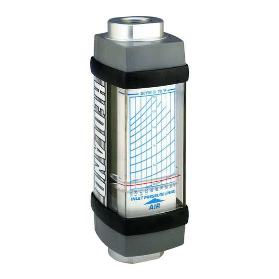
Introduction INTRODUCTION The Inline Pneumatic Flow Meter is a rugged industrial class flow rate indicator and is offered in aluminum, brass, T303 and T316 stainless steel models to monitor pressurized air lines and a wide range of other compressed gases . Available in seven port sizes from 0 .25…3 inch for flow ranges from 0 .5…5 scfm (0 .2…2 .2 l/sec) through 200…2200 scfm (75…1130 l/sec), meters are calibrated at 1 .0 specific gravity . -
Page 4: Operating Principle
Operating Principle OPERATING PRINCIPLE The Flow Meter is a variable area instrument . A sharp-edged orifice, located within the piston assembly, forms an annular opening with the contoured metering cone . The piston assembly carries a cylindrical PPS/ceramic magnet that is magnetically coupled to an external indicating magnet, which moves precisely in direct response to movement of the piston . -
Page 5: Installation
Installation INSTALLATION THIS PRODUCT SHOULD BE INSTALLED AND SERVICED BY A TECHNICALLY QUALIFIED PERSONNEL TRAINED IN MAINTAINING INDUSTRIAL CLASS FLOW INSTRUMENTATION AND PROCESSING EQUIPMENT. READ INSTRUCTIONS THOROUGHLY BEFORE INSTALLING THE UNIT. IF YOU HAVE ANY QUESTIONS REGARDING PRODUCT INSTALLATION OR MAINTENANCE, CALL YOUR LOCAL SUPPLIER FOR MORE INFORMATION. THIS METER MAY CONTAIN RESIDUAL AMOUNTS OF TEST FLUID AT THE TIME OF SHIPMENT. -
Page 6: Installation Recommendations
Installation Installation Recommendations The inline flow meter is a simple device to install . However, the following measures are recommended for reliable, trouble- free operation: 1 . Piping should be accurately aligned and of correct length . The high pressure body of the flow meter can withstand shock and flow/pressure pulsation . - Page 7 Installation Place wrench on meter ats on the same side plumbing is being tightened Never place wrench on meter ats opposite plumbing being tightened Figure 3: Installing meter 3 . After installation, rotate the meter by hand to the view flow scale . See Figure 4.
-
Page 8: Installing The Test Kit Flow Meter
Installation Installing the Test Kit Flow Meter 1 . Mount the VA High Pressure Test Kit Flow Meter so fluid is traveling in the direction of the flow arrow . See Figure 2 on page 2 . Install the test kit at any location in the pneumatic circuit that is suitable for viewing . To connect the test kit into the piping system, place an open-ended wrench onto the test kit extended cap on the inlet side or on the test kit wrench flat on the outlet side adjacent to the pipe connection being installed . -
Page 9: Operation
Operation OPERATION Multi-Pressure Flow Scales The inline pneumatic flow meter is offered with a multi-pressure flow scale to visually indicate air flow rates in standard cubic feet per minute (scfm) at 1 .0 s .g . (70° F at 100 psi) or liters per second (l/sec) at 1 .0 s .g . (21° C at 6 .9 bar) . The multi-pressure scale design allows for use at line pressures from 40…130 psi in 10 psi increments (3 .0…9 .0 bar in 1 bar increments) . -
Page 10: Application Information
Operation Application Information Compressibility of Gases Gases are significantly compressible so their density varies with pressure and temperature . Use Table 1 to convert indicated scfm flow rates to actual scfm flow rates for your application . Effects of Specific Gravity Table 3 Standard scales are calibrated for air with a specific gravity of 1 .0 . -
Page 11: Maintenance
Maintenance MAINTENANCE BEFORE ATTEMPTING TO REMOVE THE FLOW METER FROM THE LINE, CHECK THE SYSTEM TO CONFIRM THAT LINE PRESSURE HAS BEEN REDUCED TO ZERO PSI. FAILURE TO FOLLOW THESE INSTRUCTIONS COULD RESULT IN SERIOUS PERSONAL INJURY OR DEATH AND/OR DAMAGE TO THE EQUIPMENT. 1 . -
Page 12: Fluid Selection Chart
Fluid Selection Chart FLUID SELECTION CHART External Internal Body Pressure Dust Guards Material Seals Correction Fluid Specific Gravity Factor of Standard Scale 1 .00 1 .000 Argon (A) 1 .38 1 .175 Carbon Dioxide (CO 1 .53 1 .237 Freon 11 (CCI 4 .92 2 .218 Freon 12 (CCI... -
Page 13: Flow Vs. Pressure Drop
Flow vs. Pressure Drop FLOW VS. PRESSURE DROP Air/Compressed Gases 3-30 ¼" 15-150 ½" 2-20 10-100 1-10 5-50 3-25 0.5-5 FLOW, SCFM FLOW, SCFM 100-1000 ¾" / 1" 1-¼" / 1-½" 25-250 10-100 80-800 15-150 3-25 60-600 40-400 20-200 5-50 FLOW, SCFM FLOW, SCFM 3"... -
Page 14: Air/Compressed Test Kits
Flow vs. Pressure Drop Air/Compressed Test Kits 3-30 ¼" 15-150 ½" 2-20 10-100 1-10 5-50 3-25 0.5-5 FLOW, SCFM FLOW, SCFM 100-1000 ¾" / 1" 1-¼" / 1-½" 25-250 10-100 80-800 15-150 3-25 60-600 40-400 20-200 5-50 FLOW, SCFM FLOW, SCFM Figure 11: Air and compressed gasses flow vs pressure drop test kits Air/Caustic and Corrosive Gases 3-30... -
Page 15: Specifications
Specifications SPECIFICATIONS Standard -20…240° F (-29…116° C) -20…400° F (-29…205° C) Continuous Temperature Range Hostile environment: 400…500° F (205…260° C) Intermittent "Pressure vs. temperature chart" on page 12 for more information . 1000 psi (69 bar) maximum Aluminum/brass models 3" Sizes; 250 psi (17 bar) maximum Pressure Rating Stainless steel models 1500 psi (103 bar) maximum... -
Page 16: Dimensions
Dimensions DIMENSIONS Standard Meters Nominal Length Length Width Depth Offset Flats Height Port Size in. (mm) in. (mm) in. (mm) in. (mm) in. (mm) in. (mm) in. (mm) 1/4 (SAE 6) 4 .80 (122) 6 .12 (155) 1 .68 (43) 1 .90 (48) 0 .82 (21) 0 .88 (22) -
Page 17: Test Kits
Dimensions Test Kits Nominal Length Length Width Depth Offset Flats Height Port Size in. (mm) in. (mm) in. (mm) in. (mm) in. (mm) in. (mm) in. (mm) 1/4 (SAE 6) 4 .80 (122) 6 .12 (155) 1 .68 (43) 1 .90 (48) 0 .82 (21) 0 .88 (22) 5 .00 (127)
Need help?
Do you have a question about the Hedland T303 and is the answer not in the manual?
Questions and answers