
Related Manuals for Badger Meter Dynasonics TFX-5000


Summary of Contents for Badger Meter Dynasonics TFX-5000
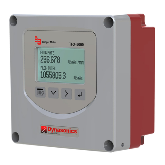
- Page 1 Transit Time Ultrasonic Flow Meters TFX-5000 Meter User Manual TTM-UM-02222-EN-04 (October 2019)
-
Page 2: Table Of Contents
Transit Time Ultrasonic Flow Meters, TFX-5000 Meter CONTENTS Scope of This Manual Typographic Conventions Unpacking and Inspection Safety Terminology and Symbols Considerations Introduction Dimensions Remote Enclosure Wall Mount Bracket Panel Mount Enclosure Operation Keypad Operation on the Home Screen Keypad Operation in the Menu Structure Selecting an Option in a Parameter Selection List Entering a Number Installation... - Page 3 User Manual Installing the MicroSD Card Connecting the USB Cable Initial Meter Setup Menu Map Parameter Descriptions by Menu Main Menu Structure Setup > Units Setup > Meter > Pipe Setup > Meter > Fluid Setup > Meter > Flow Setup Setup >...
- Page 4 Transit Time Ultrasonic Flow Meters, TFX-5000 Meter Data Logging Storage Configuration Software Part Number Construction TFX-5000 Flow Meters for Pipes 2 in and Smaller TFX-5000 Flow Meters for Pipes 2 in and Smaller for Hazardous Locations TFX-5000 Flow Meters for Pipes 2 5 in and Larger TFX-5000 Flow Meters for Pipes 2 5 in and Larger for Hazardous Locations TFX-5000 Energy Meters for Pipes 2 in and Smaller TFX-5000 Energy Meters for Pipes 2 5 in and Larger...
-
Page 5: Scope Of This Manual
Scope of This Manual SCOPE OF THIS MANUAL This manual is intended to help you get the TFX-5000 meter up and running quickly Read this manual carefully before attempting any installation or operation Keep the manual accessible for future reference Typographic Conventions In step-by-step instructions, bold text indicates items on the screen you need to select or act upon •... -
Page 6: Introduction
Introduction INTOODUCTION WARNING POTENTIAL ELECTROSTATIC CHARGING HAZARD. THE NONMETALLIC PART OF THE ENCLOSURE MUST BE CLEANED WITH A DAMP CLOTH TO ELIMINATE THE RISK OF STATIC ELECTRICITY. The TFX-5000 transit time meter measures volumetric flow and heating/cooling energy rates in clean liquids as well as those with small amounts of suspended solids or aeration, such as surface water or sewage TFX-5000 ultrasonic flow and energy meters clamp onto the outside of pipes and do not contact the internal liquid The TFX-5000 meter is available in two versions:... -
Page 7: Wall Mount Bracket
Dimensions Wall Mount Bracket 2.00 in. 2.50 in. 2.00 in. (50.80 mm) (63.50 mm) (50.80 mm) 2.00 in. (50.80 mm) 2.50 in. (63.50 mm) 2.00 in. (50.80 mm) Figure 3: Wall mount enclosure dimensions Panel Mount Enclosure Customer-supplied panel 1.38 in. 1.25 in. -
Page 8: Operation
Operation OPEOATION Keypad Operation on the Home Screen The MENU/BACK key enters menu structure The DOWN ARROW key toggles between flow rate, flow total, velocity and flow rate with flow total The RIGHT ARROW key has no function The ENTER key has no function Keypad Operation in the Menu Structure The cursor bar highlights the submenu or parameter that will be viewed or edited The scroll bar on the right indicates the relative position the cursor bar is at on the list when there are more than 4 items... -
Page 9: Selecting An Option In A Parameter Selection List
Operation Selecting an Option in a Parameter Selection List The active option in the parameter list has a filled-in box on the left side The scroll bar on the right indicates the relative position the cursor bar is at on the list when there are more than 4 items •... -
Page 10: Installation
Installation INSTALLATION Overview Each of the installation steps that follow is explained in detail on page 11 through page 12 The actual installation procedures differ slightly, depending on whether the transducers are fixed or adjustable If the transducers are fixed, you will: 1 Install the transducers 2 Install the transmitter 3 Wire the transmitter... -
Page 11: Installing A Meter With A Remote Transmitter And Fixed Transducers
Installation Installing a Meter with a Oemote Transmitter and Fixed Transducers • Locate the transmitter within the length of the transducer cables supplied or exchange the cable for one of proper length • Figure 2 on page 6 for enclosure and mounting dimension details Allow enough room for door swing, maintenance and conduit entrances MPOOTANT When routing wires to the transmitter, make sure the cables are not twisted, pinched or hanging loosely. -
Page 12: Installing A Meter With A Remote Transmitter And Adjustable Transducers
Installation OTEE: Use suitably certified fittings/plugs to maintain the watertight integrity of the enclosure Generally, the right conduit hole (viewed from front) is used for power, the left conduit hole for transducer connections, and the center holes are used for I/O wiring 8 Install the wires through the gland nuts and connect the wires to the removable terminal blocks See “Wiring the Transmitter”... -
Page 13: Installing A Panel-Mount Meter
Installation 6 Use conduit holes where cables enter the enclosure from the bottom Use suitably certified plugs to seal any holes that are not used for cable entry A cable gland kit is included for inserting the transducer and power cables 1/2 in. -
Page 14: Wiring The Transmitter
Wiring the Transmitter WIOING THE TOANSMITTEO IMPOOTANT: Select field wiring means rated for 5° C above the maximum area temperature when it is possible that the temperature will exceed 55° C To access terminal strips for wiring, loosen the 4 enclosure captive screws Grasp and lift the cover and open it to the left The cover remains attached and the left screws act as a hinge Electrical Symbols Function... -
Page 15: Rated Conditions Of Terminals
• 9…28V DC, 20…26VAC Wire 20AWG UL AWM 1007 Type 1007 • Transducer Cables Badger Meter supplied cable • Digital Outputs/Inputs, Current Output, RS-485, RTD or Encoder Interface • Wire 28…12 AWG UL AWM 1007 Type 1007 Wiring the Transducer... -
Page 16: Power
Wiring the Transmitter Power Connect power to the screw terminal block in the transmitter • Low voltage power can use any available conduit hole in the enclosure • Line voltage AC power must use the right conduit hole, which is aligned with the terminal block on the AC power board •... -
Page 17: Mains Power
Wiring the Transmitter Mains Power IMPOOTANT: The measuring device does not have an internal circuit breaker. For compliance with IEC 61010-1, a switch in close proximity to the transmitter is required so that the power supply line can be easily disconnected from the mains. The transmitter may be operated from 90…250V AC, 47…63 Hz, 24VA maximum power source OTEE: Mains AC-powered transmitters are protected with 1A, 250V AC, 5×20 mm, slow-blow, field-replaceable fuse... -
Page 18: Digital Outputs Wiring
Wiring the Transmitter NOTE: 4…20 OUT 2 available TP605 External Equipment Black with Energy model only. TP604 No Connect No Connect 4…20 OUT 2 Current #2 Output 4…20 OUT 1 Current #1 Output 800 Ohms max. +24V DC Source In No Connect TB600 (Acceptable wire sizes: 28…12 AWG) -
Page 19: Digital Input Wiring
Wiring the Transmitter OS485 Output The RS485 feature allows up to 126 transmitters to be placed on a single three-wire cable up to 4000 feet All transmitters are assigned a unique numeric address that allows all of the transmitters on the cable network to be independently accessed Either Modbus RTU or BACnet MS/TP protocol is used to interrogate the transmitters Flow rate and total can be monitored over the digital communications bus When a USB programming cable is connected, the RS485 and frequency outputs are disabled... -
Page 20: Auxiliary Output Card Wiring
Wiring the Transmitter External Equipment External Equipment TB900 TB900 Temp #1 RTD1 Ex + Temp #1 RTD1 Ex + RTD1 Sense + RTD1 Sense + RTD1 Sense - RTD1 Sense - RTD1 Ex - RTD1 Ex - PT100 or PT1000 RTDs PT100 or PT1000 RTDs RTD2 Ex + RTD2 Ex +... -
Page 21: Connecting The Usb Cable
Menu Map Connecting the USB Cable Use a USB cable when connecting a TFX-5000 meter to a computer with SoloCUE Flow Device Manager software WARNING DO NOT USE THE MINI USB PORT IN A HAZARDOUS LOCATION WHERE EXPLOSIVE GAS OR DUST IS PRESENT. DO NOT OPEN THE TRANSMITTER WHILE POWERED IF WATER OR SPRAY COULD CONTACT ELECTRONICS OR INTERIOR. -
Page 22: Menu Map
Menu Map MENU MAP NOTE: Passcode levels for write access to each menu are as follows: HOME SCREEN Press (O) = Operator, Service or Admin to toggle Flow Rate *Energy Total the options. (S) = Service or Admin Flow Total *Temp #1 / Temp #2 (A) = Admin Velocity... -
Page 23: Parameter Descriptions By Menu
Parameter Descriptions by Menu PAOAMETEO DESCOIPTIONS BY MENU Main Menu Structure The transmitter’s firmware has a hierarchical menu structure See "Menu Map" on page 22 for a visual path to the parameters The five Main Menus used in the transmitter firmware are as follows: Menu Function SETUP... - Page 24 Parameter Descriptions by Menu Units Submenus Options/Descriptions Select the units for the flow total displayed on the Home Screen FLOW TOTAL UNITS are automatically converted into the selected option: Option Units Option Units US Gallons Fluid BBL Fluid Barrel (31 5 Gal) MGAL Million US Gallons Liter...
- Page 25 Parameter Descriptions by Menu Setup > Meter Contains all of the configuration parameters for setting the meter Requires service level passcode or higher if security is enabled An asterisk (*) indicates the parameter default Meter Submenus Options/Descriptions Select the transducer type: UZ 2 MHZ Option UZ when ordered with the TFX-5000 meter CX 2 MHZ...
-
Page 26: Setup > Meter > Pipe
Parameter Descriptions by Menu Setup > Meter > Pipe An asterisk (*) indicates the parameter default Pipe Submenus Options/Descriptions STAINLESS 302/303 STAINLESS 430 IRON - DUCTILE POLYPROPYLENE STAINLESS 304 ALUMINUM HD POLYETHYLENE STAINLESS 304L BRASS NAVAL LD POLYETHYLENE PIPE MATERIAL *STAINLESS 316 CARBON STEEL PFA TEFLON... -
Page 27: Setup > Meter > Fluid
Parameter Descriptions by Menu Setup > Meter > Fluid Fluid Submenus Options/Descriptions Water - Tap Acetone Ethylene Glycol 30% Kerosene Propylene Glycol 30% Raw Sewage Ammonia Gasoline Methanol Stoddard Solvent Water - Distilled Benzene Glycerin Oil Diesel #1 Sulfuric Acid 96% FLUID Water - Sea 3 5% Ethanol Isopropanol... -
Page 28: Setup > Meter > Advanced
Parameter Descriptions by Menu Setup > Meter > Advanced An asterisk (*) indicates the parameter default Dynasonics Calculation EN1434 TYPE Rate of Heat Delivery = Q × (Tin – Tout) × C × ρ Where HEAT CALCULATION Volumetric flow rate (Energy meter only) Tin = Temperature at the inlet... - Page 29 Parameter Descriptions by Menu For example, if the average flow rate is 100 gpm and the Hysteresis is set to 10%, a filter window of 90…110 gpm is established Successive flow measurements that reside within that window are recorded and averaged in accordance with the Damping setting Flow readings outside of the window are rejected or accepted in accordance with the Bad Data Rejection setting Filter settings for this example:...
- Page 30 Parameter Descriptions by Menu 3 Samples Outside Flow Outside Hysteresis Limit Hysteresis Limit Sample Limits ±10% Hysteresis Bad Data Rejection Limit Window Flow Figure 39: Bad data (rejection) The flow rate is again outside the original ±10% Hysteresis window, but the data exists for a time period greater than the Bad Data Rejection window In this instance, the meter interprets the data as a new valid flow rate and moves the Hysteresis window to correspond with the new established flow rate 4 Samples Outside...
-
Page 31: Setup > Meter > Calibration
Parameter Descriptions by Menu Setup > Meter > Calibration An asterisk (*) indicates the parameter default Calibration Submenus Options/Descriptions FACTORY FACTOR MODE Select FIELD to set the zero and use the sensor and scale factors of the transducers *FIELD The zero offset entered during factory calibration ZERO is for reference only and ZERO most likely the ZERO VALUE for your installation will be different from the factory ZERO Numeric display;... -
Page 32: Setup > Input/Output > Current #1
Parameter Descriptions by Menu Setup > Input/Output > Current #1 Requires service level passcode or higher if security is enabled The current output, reset input and frequency/pulse/status output can be set up through the SETUP > INPUT/OUTPUT menus An asterisk (*) indicates the parameter default Current #1 Submenus Options/Descriptions *FLOW RATE... -
Page 33: Setup > Inputs/Output > Output #1 (Or Output #2)
Parameter Descriptions by Menu Setup > Inputs/Output > Output #1 (or Output #2) Output #1 and output #2 can operate independently as a frequency, totalizer pulse, direction status or alarm status output In the SETUP > INPUT/OUTPUTS > OUTPUT #1 (OR OUTPUT #2) > MODE menu, select the MODE of operation Then go to the PARAMETERS menu to set up the operation for that MODE An asterisk (*) indicates the parameter default Output #1 Submenus Options/Descriptions... - Page 34 Parameter Descriptions by Menu Output #1 Submenus Options/Descriptions *POSITIVE FLOW NEGATIVE FLOW Select whether the pulse output accumulates only on BIDIRECTIONAL FLOW positive (forward) flow, only on negative (reverse) flow OUTPUT or anytime flow occurs regardless of the flow direction Also available for energy meters: SOURCE (bidirectional) For bidirectional, assign the direction status...
-
Page 35: Setup > Inputs/Output > Input
Parameter Descriptions by Menu Setup > Inputs/Output > Input An asterisk (*) indicates the parameter default Input Submenus Options/Descriptions DISABLED MODE *RESET TOTAL Select the action to take when the input is active (based on the state) UNLATCH ALARM *ACTIVE ON HIGH STATE Select the voltage level to make the input active ACTIVE ON LOW... -
Page 36: Setup > Communications
Parameter Descriptions by Menu Setup > Communications Requires service level passcode or higher if security is enabled For addressing information, see the "TFX-5000 Meter Modbus RTU Protocol" user manual or the "TFX-5000 Meter BACnet MS/TP Protocol" user manual, available at www.badgermeter com An asterisk (*) indicates the parameter default Communication... - Page 37 Parameter Descriptions by Menu Communication Options/Descriptions Submenus NoteE: WEBSERVER is READ ONLY WEBSERVER *ENABLED DISABLED CLIENT TIMEOUT 0…65,535 ms DEVICE INSTANCE BACnet ID range: 0…99,999,999 *DISABLED DHCP ENABLED Numeric entry ### ### ### ### Enter a value from 1…255 for the first value and 0-255 for the IP ADDRESS remaining values Option not available if DHCP is enabled Numeric entry ### ### ### ### Enter each value from 0…255 Option not available if DHCP is...
- Page 38 Parameter Descriptions by Menu Communication Options/Descriptions Submenus NoteE: WEBSERVER is READ ONLY WEBSERVER *DISABLED ENABLED *DISABLED DHCP ENABLED Numeric entry ### ### ### ### Enter a value from 1…255 for the first value and 0…255 for the IP ADDRESS remaining values Option not available if DHCP is enabled Numeric entry ### ### ### ### Enter a value from 1…255 for the first value and 0…255 for the IP ADDRESS remaining values Option not available if DHCP is enabled...
-
Page 39: Setup > Data Logging (Service Level Access)
Parameter Descriptions by Menu Setup > Data Logging (Service Level Access) Requires service level passcode or higher if security is enabled Due to FAT32 limitation on the microSD card, if the file size exceeds 4 GB, the log file will be closed and a new file started Both files will be accessible The name of the files are FILE0001 txt, FILE0002 txt, and so on Log files are automatically saved as txt files to the microSD card Before removing the microSD card, change the LOG MODE to DISABLED With an 8 GB microSD card installed, the card will have enough memory to last about 1-1/2 years when logging 8 parameters at a 1 second time interval... -
Page 40: Setup > Passcode Setup > Security
Only the ADMIN level can reset passcodes If the ADMIN passcode is lost and the passcodes need to be reset, you can contact Badger Meter, provide a recovery code to the representative and request a temporary passcode To generate a recovery code:... -
Page 41: Display Menu
An asterisk (*) indicates the parameter default Information Submenus Options/Descriptions VENDOR BADGER METER MODEL TFX-5000 P.N.: Badger Meter part number S.N. Serial Number FW VERSION Firmware Version xx xx xxx CAL. DATE Calibration Date YYYY-MM-DD DATE CODE Manufacture Date YYYY-MM-DD... -
Page 42: Diagnostics Menu
Parameter Descriptions by Menu Diagnostics Menu The DIAGNOSTICS menu displays system status and allows you to clear the history, reset to factory defaults and reboot the system An asterisk (*) indicates the parameter default Diagnostics Submenus Options/Descriptions SIGNAL STRENGTH Read-only numeric with message to indicate the quality of the ultrasonic signal HISTORY Chronological list of 120 past errors, alarms and warning messages DELTA TIME FILTERED... -
Page 43: Reset Menu
Parameter Descriptions by Menu Diagnostics Submenus Options/Descriptions HH:MM:SS (24 hour TIME Displays the time clock) DATE YYYY-MM-DD Displays the date POWER ON TIME In seconds Flow Simulation provides output and display simulation based on a percentage of the full scale flow Simulation will not 100% accumulate the totalizers The range of simulation includes 0…100% of the full scale flow... -
Page 44: Troubleshooting
Troubleshooting TOOUBLESHOOTING Warning and alarm messages are classified according to NAMUR 107 standards Out of Specification Messages Warning and alarm messages occur when the flow meter is operational, but the readings might be out of specification or an operator might need to take action If a warning or alarm condition occurs, a warning/alarm icon with code will appear in the at the bottom of the Home Screen The flow rate and flow total will continue to be displayed Error Messages An error condition occurs when the flow rate cannot be determined, such as when the signal strength is too low If an error... - Page 45 Troubleshooting Out-of-Specification Codes Code Description Correction S01 ELECTRONIC WARNING Fault detected and meter rebooted Contact factory, update firmware, or repair or replace transmitter Check calibration If it does not match the calibration settings on the transducer serial tag, enter field calibration settings Return to the S02 DEFAULT FAILED Reset to factory defaults failed Home Screen and continue to operate (if the reset to factory defaults is...
-
Page 46: Symptoms
Troubleshooting Code Description Correction S95 TEMP #2 HIGH Temp #2 is above high alarm setting Check fluid temperature and RTD #2 Check alarm settings for Output #1 S96 TEMP #2 HIGH Temp #2 is above high alarm setting Check fluid temperature and RTD #2 Check alarm settings for Output #2 S97 TEMP #2 HIGH Temp #2 is above high alarm setting Check fluid temperature and RTD #2 Check alarm settings for Output #3... - Page 47 Troubleshooting Symptom: Unstable flow. Possible Causes Oecommended Action • Installation issues • Check process loop for variations of entrained air which will impact the flow • Flow instability • Check for pump induced flow instability • Transducers mounting is loose •...
-
Page 48: Replacement Procedures
Replacement Procedures OEPLACEMENT POOCEDUOES WARNING DISCONNECT POWER BEFORE OPENING THE ENCLOSURE. Tools Oequired • A Phillips #2 screwdriver • A flat blade screwdriver • Tweezers for electronics • A workbench that prevents ESD damage to the electronics CONTAINS PARTS AND ASSEMBLIES SUSCEPTIBLE TO DAMAGE BY ELECTROSTATIC DISCHARGE (ESD). BEFORE PICKING UP AN ESD-SENSITIVE ELECTRONIC COMPONENT, DISCHARGE YOURSELF BY TOUCHING A GROUNDED BARE METAL SURFACE OR APPROVED ANTI-STATIC MAT. -
Page 49: Replacing The Communication Or Dry Contact Board
Replacement Procedures Oeplacing the Communication or Dry Contact Board 1 Turn off the power 2 Open the enclosure 3 Disconnect the wires from the communication board 4 Remove (2) M3 pan head phillips screws that secure the cover over the communication board 5 Remove the cover 6 Remove the remaining (2) M3 pan head phillips screws that secure the communications board 7 Lift the communications board straight out to unplug from the main board... -
Page 50: Specifications
Specifications SPECIFICATIONS System Liquid Types Most clean liquids or liquids containing small amounts of suspended solids or gas bubbles Medium and Large Pipes (RZ, ± 0 5% ± 0 0 049 ft/s (0 015 m/s) NZ, WZ, HZ, LZ, YZ, JZ, KZ) Flow Accuracy 1 in (25 mm) and larger = ±1% ±... -
Page 51: Transducers
Specifications Flow Meter Energy Meter One 16-bit, isolated, max 800 Ohms, internal or Two 16-bit, isolated, max 800 Ohms, internal or 0/4…20 mA output external power external power Digital input One 5…30V DC, isolated, externally or internally sourced, reset totalizer or alarm output Two selectable pulse, alarm, flow direction, sink isolated Three selectable pulse, frequency, alarm, flow direction, open collector, 5…30V DC, max 50 mA externally or... -
Page 52: Rtd Kits
RTD Kits OTD Kits Part Description Installation OTD Type Construction Temperature Oange Number 68996-001 RTD matched pair; 15 ft (4 5 m) cable Pipe clamp, Aluminum body, -58…356° F 68996-002 RTD matched pair; 50 ft (15 m) cable Pt 1000, Class A surface mount, IP54 silicone cable jacket (-50…180°... -
Page 53: Part Number Construction
Part Number Construction PAOT NUMBEO CONSTOUCTION TFX-5000 Flow Meters for Pipes 2 in. and Smaller DQ - G - - XX - Model TFX-5000 Ultrasonic Clamp-On Meter Certification General Area US/Canada, CE Transducer Type 1/2 inch ANSI Pipe 3/4 inch ANSI Pipe 1 inch ANSI Pipe 1-1/4 inch ANSI Pipe 1-1/2 inch ANSI Pipe... -
Page 54: Tfx-5000 Flow Meters For Pipes 2 In And Smaller For Hazardous Locations
Part Number Construction TFX-5000 Flow Meters for Pipes 2 in. and Smaller for Hazardous Locations DQ - B - - XX - Model TFX-5000 Ultrasonic Clamp-On Meter Certification Hazardous Location, Class I, Division 2 Transducer Type 1/2 inch ANSI Pipe 3/4 inch ANSI Pipe 1 inch ANSI Pipe 1-1/4 inch ANSI Pipe... -
Page 55: Tfx-5000 Flow Meters For Pipes 2 5 In And Larger
Part Number Construction TFX-5000 Flow Meters for Pipes 2.5 in. and Larger DQ - G - - XX - Model TFX-5000 Ultrasonic Clamp-On Meter Certification General Area US/Canada, CE Transducer Type Medium pipe, 2.5 in. (65 mm) or larger Medium pipe, submersible, 2.5 in. (65 mm) or larger 2.5…6 inches (65…150 mm) Easy Rail (not available with conduit) 2.5…12 inches (65…300 mm) Easy Rail (not available with conduit) Medium pipe, high temperature (not available with conduit) -
Page 56: Tfx-5000 Flow Meters For Pipes 2 5 In And Larger For Hazardous Locations
Part Number Construction TFX-5000 Flow Meters for Pipes 2.5 in. and Larger for Hazardous Locations DQ - - XX - Model TFX-5000 Ultrasonic Clamp-On Meter Certification Hazardous Location, Class I, Division 2 Transducer Type Medium pipe, 2.5 in. (65 mm) or larger Medium pipe, submersible, 2.5 in. -
Page 57: Tfx-5000 Energy Meters For Pipes 2 In And Smaller
Part Number Construction TFX-5000 Energy Meters for Pipes 2 in. and Smaller DR - G - - XX - Model TFX-5000 Ultrasonic Clamp-On Meter Certification General Area US/Canada, CE Transducer Type 1/2 inch ANSI Pipe 3/4 inch ANSI Pipe 1 inch ANSI Pipe 1-1/4 inch ANSI Pipe 1-1/2 inch ANSI Pipe 2 inch ANSI Pipe... -
Page 58: Tfx-5000 Energy Meters For Pipes 2 5 In And Larger
Part Number Construction TFX-5000 Energy Meters for Pipes 2.5 in. and Larger DR - G - - XX - Model TFX-5000 Ultrasonic Clamp-On Meter Certification General Area US/Canada, CE Transducer Type Medium pipe, 2.5 in. (65 mm) or larger Medium pipe, submersible, 2.5 in. (65 mm) or larger 2.5…6 inches (65…150 mm) Easy Rail (not available with conduit) 2.5…12 inches (65…300 mm) Easy Rail (not available with conduit) Medium pipe, high temperature (not available with conduit) -
Page 59: North American Pipe Schedules
North American Pipe Schedules NOOTH AMEOICAN PIPE SCHEDULES Cast Iron Pipe, Standard Classes, 3…10 inch Class Size 3 80 3 96 3 96 3 96 Wall 0 39 0 42 0 45 0 48 — — — — 3 02 3 12 3 06 3 00... - Page 60 The Americas | Badger Meter | 4545 West Brown Deer Rd | PO Box 245036 | Milwaukee, WI 53224-9536 | 800-876-3837 | 414-355-0400 México | Badger Meter de las Americas, S.A. de C.V. | Pedro Luis Ogazón N°32 | Esq. Angelina N°24 | Colonia Guadalupe Inn | CP 01050 | México, DF | México | +52-55-5662-0882 Europe, Eastern Europe Branch Office (for Poland, Latvia, Lithuania, Estonia, Ukraine, Belarus) | Badger Meter Europe | ul.
Need help?
Do you have a question about the Dynasonics TFX-5000 and is the answer not in the manual?
Questions and answers