
Related Manuals for Badger Meter Dynasonics TFX-500w


Summary of Contents for Badger Meter Dynasonics TFX-500w
- Page 1 Transit Time Ultrasonic Flow Meters TFX-500w Clamp-On Meter User Manual TTM-UM-02537-EN-06 (May 2021)
- Page 2 Transit Time Ultrasonic Flow Meters, TFX-500w Clamp-On Meter Page ii TTM-UM-02537-EN-06 May 2021...
-
Page 3: Table Of Contents
User Manual CONTENTS Scope of This Manual Typographic Conventions Unpacking and Inspection Safety Terminology and Symbols Considerations Introduction Dimensions Operation Keypad Operation on the Home Screen Keypad Operation in the Menu Structure Selecting an Option in a Parameter Selection List Entering a Number Installation Overview... - Page 4 Transit Time Ultrasonic Flow Meters, TFX-500w Clamp-On Meter Setup > Meter > Calibration Setup > Input/Output >Current Output Setup > Inputs/Output > Output #1 (or Output #2) Setup > Inputs/Output >Input Setup > Communications Setup > Passcode Setup Display Menu Information Menu Diagnostics Menu Reset Menu...
-
Page 5: Scope Of This Manual
Scope of This Manual SCOPE OF THIS MANUAL This manual is intended to help you get the TFX-500w meter up and running quickly Read this manual carefully before attempting any installation or operation Keep the manual accessible for future reference Typographic Conventions In step-by-step instructions, bold text indicates items on the screen you need to select or act upon •... -
Page 6: Introduction
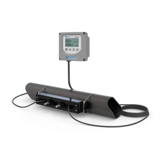
Introduction INTRODUCTION The TFX-500w ultrasonic transit time flow meter measures volumetric flow of clean water in pipes 10 in or smaller By clamping on the outside of the pipe, the ultrasonic meter installs without cutting or tapping the pipe Transit time flow meters use two transducers that clamp on to the outside of a pipe and never directly contact the fluids The transducers function as both ultrasonic transmitters and receivers The flow meters operate by alternately transmitting and receiving a frequency-modulated burst of sound energy between the two transducers The burst is first transmitted in the direction of fluid flow and then against fluid flow Sound energy in a moving liquid is carried faster when it travels in the... -
Page 7: Operation
Operation OPERATION Keypad Operation on the Home Screen The MENU/BACK key enters menu structure The DOWN ARROW key toggles between flow rate, flow total, velocity and flow rate with flow total The RIGHT ARROW key has no function The ENTER key has no function Keypad Operation in the Menu Structure The cursor bar highlights the submenu or parameter that will be viewed or edited The scroll bar on the right indicates the relative position the cursor bar is at on the list when there are more than 4 items... -
Page 8: Selecting An Option In A Parameter Selection List
Operation Selecting an Option in a Parameter Selection List The active option in the parameter list has a filled-in box on the left side The scroll bar on the right indicates the relative position the cursor bar is at on the list when there are more than 4 items •... -
Page 9: Installation
Installation INSTALLATION Overview Each of the installation steps that follow is explained in detail on page 10 through page 12 The actual installation procedures differ slightly, depending on whether the transducers are fixed or adjustable If the transducers are fixed, you will: 1 Install the transducers 2 Install the transmitter 3 Wire the transmitter... -
Page 10: Installing A Meter With A Remote Transmitter And Fixed Transducers
Installation Installing a Meter with a Remote Transmitter and Fixed Transducers • Locate the transmitter within the length of the transducer cables supplied or exchange the cable for one of proper length • Figure 2 on page 6 for enclosure and mounting dimension details Allow enough room for door swing, maintenance and conduit entrances MPORTANT When routing wires to the transmitter, make sure the cables are not twisted, pinched or hanging loosely. -
Page 11: Installing A Meter With A Remote Transmitter And Adjustable Transducers
Installation Installing a Meter with a Remote Transmitter and Adjustable Transducers • Locate the transmitter within the length of the transducer cables supplied or exchange the cable for one of proper length • Figure 2 on page 6 for enclosure and mounting dimension details Allow enough room for door swing, maintenance and conduit entrances MPORTANT When routing wires to the transmitter, make sure the cables are not twisted, pinched or hanging loosely. -
Page 12: Installing A Meter With An Integral Transmitter
Wiring the Transmitter Installing a Meter with an Integral Transmitter 1 Install the meter on the pipe according to the instructions in the user manual for your particular transducer Pipe Figure 15: Install the meter onto the pipe 2 Partially loosen the 2 enclosure captive screws on the left side of the transmitter cover Completely loosen the 2 screws on the right side Grasp and lift the cover and open it to the left The cover remains attached and the left screws act as a hinge 3 If necessary, rotate the transmitter 180°... -
Page 13: Wiring The Transmitter
Wiring the Transmitter WIRING THE TRANSMITTER IMPORTANT: Select field wiring means rated for 5° C above the maximum area temperature when it is possible that the temperature will exceed 55° C To access terminal strips for wiring, loosen the 4 enclosure captive screws Grasp and lift the cover and open it to the left The cover remains attached and the left screws act as a hinge Electrical Symbols Function... - Page 14 Wiring the Transmitter OTE: Transducer cables have two wire-color combinations For the blue and white combination, the blue wire is positive (+) and the white wire is negative (–) For the red and black combination, the red wire is positive (+) and the black wire is negative (–) The transducer wires are labeled to indicate which pair is upstream or downstream 4 Connect power to the screw terminal block in the transmitter using the conduit hole in the center of the enclosure Use wiring practices that conform to local and national codes such as The National Electrical Code Handbook in the U S...
- Page 15 Wiring the Transmitter Digital Outputs Wiring TB600 TB600 ISO 24V External Equipment External Equipment V DC (15 . . . 30V DC) R-Pullup R-Pullup Control Out1 10 Ohms Control Out1 Control Out2 Control Out2 ISO Ground ISO Ground Figure 22: Typical control out 1 & 2 interface with internal pullups active Figure 23: Typical control out 1 &...
-
Page 16: Initial Meter Setup
Menu Map Initial Meter Setup You can set up the meter using the TFX-500w keypad or the SoloCUE Flow Device Manager software This document addresses procedures using the TFX-500w keypad To use SoloCUE, see the "SoloCUE Flow Device Manager Installation Guide" available at www.badgermeter.com When you start the meter for the first time, you must select a language, press ENTER, then press MENU/BACK to get to BASIC SETUP... -
Page 17: Menu Map
Menu Map MENU MAP NOTE: Passcode levels for write access to each menu are as follows: (O) = Operator, Service or Admin (S) = Service or Admin (A) = Admin If no passcode is entered, all parameters can still be read. HOME SCREEN Press to toggle... -
Page 18: Parameter Descriptions By Menu
Parameter Descriptions by Menu PARAMETER DESCRIPTIONS BY MENU Main Menu Structure The transmitter’s firmware has a hierarchical menu structure See "Menu Map" on page 17 for a visual path to the parameters The five Main Menus used in the transmitter firmware are as follows: Menu Function SETUP... -
Page 19: Setup > Meter
Parameter Descriptions by Menu Units Submenus Options/Descriptions Select whether to display the flow rate, flow total, velocity or both flow rate and flow total on the display Alternatively, you can change the display from the Home Screen by pressing the DOWN button *FLOW RATE DISPLAY MODE FLOW TOTAL... -
Page 20: Setup > Meter > Pipe
Parameter Descriptions by Menu Setup > Meter > Pipe An asterisk (*) indicates the parameter default Pipe Submenus Options/Descriptions PIPE MATERIAL *STAINLESS 316 CARBON STEEL PFA TEFLON STAINLESS 347 COPPER PVC CPVC STAINLESS 410 IRON - CAST STAINLESS 302/303 STAINLESS 430 IRON - DUCTILE STAINLESS 304 ALUMINUM... -
Page 21: Setup > Meter > Spacing
Parameter Descriptions by Menu Setup > Meter > Spacing This menu is available only for adjustable spacing transducers, not fixed spacing An asterisk (*) indicates the default Spacing Submenu Options/Descriptions MODE *SPACING CALCULATED The spacing required between two transducers based on the pipe parameters Take this measurement between the lines scribed into the side of the transducers of use the scale on the rails, if used See the CALCULATED transducer user manual... - Page 22 Parameter Descriptions by Menu For example, if the average flow rate is 100 gpm and the Hysteresis is set to 10%, a filter window of 90…110 gpm is established Successive flow measurements that reside within that window are recorded and averaged in accordance with the Damping setting Flow readings outside of the window are rejected or accepted in accordance with the Bad Data Rejection setting Filter settings for this example:...
-
Page 23: Setup > Meter > Shunt
Parameter Descriptions by Menu 3 Samples Outside Flow Outside Hysteresis Limit Hysteresis Limit Sample Limits ±10% Hysteresis Bad Data Rejection Limit Window Flow Figure 28: Bad data (rejection) The flow rate is again outside the original ±10% Hysteresis window, but the data exists for a time period greater than the Bad Data Rejection window In this instance, the meter interprets the data as a new valid flow rate and moves the Hysteresis window to correspond with the new established flow rate 4 Samples Outside... -
Page 24: Setup > Meter > Calibration
Parameter Descriptions by Menu Setup > Meter > Calibration An asterisk (*) indicates the parameter default Calibration Submenus Options/Descriptions FACTORY FACTOR MODE Check that FACTOR MODE is set to FIELD *FIELD The zero offset entered during factory calibration ZERO is for reference only and ZERO most likely the ZERO VALUE for your installation will be different from the factory FACTORY SETTINGS... -
Page 25: Setup > Input/Output >Current Output
Parameter Descriptions by Menu Setup > Input/Output >Current Output The current output, reset input and frequency/pulse/status output can be set up through the SETUP > INPUT/OUTPUT menus An asterisk (*) indicates the parameter default Current Output Submenus Options/Descriptions *FLOW RATE VELOCITY OUTPUT SOURCE SIGNAL STRENGTH... -
Page 26: Setup > Inputs/Output > Output #1 (Or Output #2)
Parameter Descriptions by Menu Setup > Inputs/Output > Output #1 (or Output #2) Output #1 and output #2 can operate independently as a frequency, totalizer pulse, direction status or alarm status output In the SETUP > INPUT/OUTPUTS > OUTPUT #1 (OR OUTPUT #2) > MODE menu, select the MODE of operation Then go to the PARAMETERS menu to set up the operation for that MODE An asterisk (*) indicates the parameter default Output #1 Submenus Options/Descriptions... -
Page 27: Setup > Inputs/Output >Input
Parameter Descriptions by Menu Output #1 Submenus Options/Descriptions OUTPUT *FLOW RATE SOURCE PARAMETERS Select whether the output is active when the flow is forward or reverse When (Flow Direction Mode) FORWARD ON DIRECTION the absolute value of the flow rate is below the cutoff, the output will not be *REVERSE ON active HIGH FLOW... -
Page 28: Setup > Communications
Parameter Descriptions by Menu Setup > Communications For addressing information, see the "TFX-500w Clamp-On Meter Modbus RTU Protocol" user manual or the "TFX-500w Clamp-On Meter BACnet MS/TP Protocol" user manual, available at www.badgermeter com An asterisk (*) indicates the parameter default Communication Options/Descriptions Submenus... -
Page 29: Setup > Passcode Setup
Only the ADMIN level can reset passcodes If the ADMIN passcode is lost and the passcodes need to be reset, you can contact Badger Meter, provide a recovery code to the representative and request a temporary passcode To generate a recovery code:... -
Page 30: Display Menu
An asterisk (*) indicates the parameter default Information Submenus Options/Descriptions VENDOR BADGER METER MODEL TFX-500w P.N.: Badger Meter 24-character part number S.N. Serial Number FW VERSION Firmware Version xx xx xx CAL. DATE Calibration Date YYYY-MM-DD DATE CODE Manufacture Date YYYY-MM-DD... -
Page 31: Diagnostics Menu
Parameter Descriptions by Menu Diagnostics Menu Diagnostics Submenus Options/Descriptions SIGNAL STRENGTH Read-only numeric with message to indicate the quality of the ultrasonic signal HISTORY Chronological list of 30 past errors, alarms and warning messages DELTA TIME FILTERED Read-only ## ## ns FLOW RATE RAW Read-only unfiltered flow rate FLUID SOUND SPEED... -
Page 32: Troubleshooting
Troubleshooting TROUBLESHOOTING Warning and alarm messages are classified according to NAMUR 107 standards Out of Specification Messages Warning and alarm messages occur when the flow meter is operational, but the readings might be out of specification or an operator might need to take action If a warning or alarm condition occurs, a warning/alarm icon with code will appear in the at the bottom of the Home Screen The flow rate and flow total will continue to be displayed Error Messages An error condition occurs when the flow rate cannot be determined, such as when the signal strength is too low If an error... -
Page 33: Warning And Alarm Message Codes
Troubleshooting Warning and Alarm Message Codes Failure Codes Code Description Correction Firmware error Cannot boot up • Update firmware • Send in transmitter for repair or replace transmitter blank screen • This message is not stored in the ALARM HISTORY F02 ELECTRONIC Multiple watchdog timeout •... - Page 34 Troubleshooting Out-of-Specification Codes Code Description Correction S01 ELECTRONIC Fault detected and meter rebooted • Contact factory WARNING • Update firmware • Repair or replace transmitter S02 DEFAULT FAILED Reset to factory defaults failed • Check calibration If it does not match the calibration settings on the transducer serial tag, enter field calibration settings Return to the Home Screen and continue to operate (if the reset to factory defaults is through the transmitter)
-
Page 35: Symptoms
Troubleshooting Symptoms Symptom: Transmitter does not power up. Possible Causes Recommended Action • No power or inadequate power • Measure voltage at the power terminals and check that the voltage matches the labels by the power terminals • Blown fuse (AC Model only) •... -
Page 36: Replacement Instructions
Replacement Instructions REPLACEMENT INSTRUCTIONS This product cannot be repaired by the user and must be replaced with an equivalent certified product Repairs are only allowed to be carried out by the manufacturer or its authorized agent Front Panel Replacement A replacement front panel assembly with display/keypad (PN D080-1020-001) is available and includes the front cover, display/keypad/overlay, main board, connectors and shield A replacement front panel assembly without the display/keypad (PN D080-1020-002) is also available It includes the front cover, main board, connectors and shield The front panel is a single piece and is easily removed by unscrewing the four enclosure screws Turn off the power before... - Page 37 Replacement Instructions Figure 33: PCB shield removed 6 On the left side of the board at J501, gently slide the keypad ribbon cable retainer away from the center of the board Gently remove the keypad ribbon cable from the main board Figure 34: PCB sheild removed 7 Pull the main board away from the front panel There is a connector with long pins that connects the main board to the display board, so you will feel some friction but it should not require a lot of effort Do NOT remove the display board as...
-
Page 38: Specifications
Specifications SPECIFICATIONS System Liquid Types Water containing small amounts of suspended solids or gas bubbles Velocity Range Up to 0 1…40 ft/s (0 03…12 m/s), depending on pipe and fluid, bidirectional > 2 in (50 mm) ±1% of reading or ±0 01 ft/s (0 003 m/s), whichever is greater Flow Accuracy 1…2 in (25…50 mm) ±1% of reading ±0 03 ft/s (0 01 m/s) 3/4 in (20 mm) and smaller are accurate to ±1% full scale... -
Page 39: Transducers
Specifications Transducers Pipe/Tubing Model Construction Cable Length Pipe/Tubing Sizes Protection Materials CPVC, Ultem, Nylon cord grip DTTC 100 ft (90 m) max 0 5…2 in (12…50 mm) NEMA 6/IP67 Polyethylene cable jacket; –40…194° F (–40…90° C)* PBT glass filled, Ultem®, Nylon cord grip DTTR 300 ft (90 m) max 2 5…10 in (DN65…DN250) -
Page 40: Part Number Construction
Part Number Construction PART NUMBER CONSTRUCTION Transit Time: Pipes ≤ 2 in. CERTIFICATION General Area, CE TRANSDUCER TYPE 1/2 in. ANSI pipe 3/4 in. ANSI pipe 1 in. ANSI pipe 1-1/4 in. ANSI pipe 1-1/2 in. ANSI pipe 2 in. ANSI pipe 1/2 in. - Page 41 Part Number Construction Transit Time: Pipes > 2 in. CERTIFICATIONS General Area, CE TRANSDUCER TYPE Easy Rail | 2.5…6 in. (65…150 mm) Pipes Easy Rail | 2.5…10 in. (65…250 mm) Pipes DTTN | 2.5…10 in. (65…250 mm) Pipes DTTN (Submersible) | 2.5…10 in. (65…250 mm) Pipes DTTR | 2.5…10 in.
-
Page 42: North American Pipe Schedules
North American Pipe Schedules NORTH AMERICAN PIPE SCHEDULES Steel, Stainless Steel, PVC Pipe, Standard Classes SCH 60 X STG. SCH 80 SCH 100 SCH 120/140 SCH 180 Wall Wall Wall Wall Wall Wall 1 315 0 957 0 179 0 957 0 179 0 815 0 250... - Page 43 North American Pipe Schedules Copper Tubing, Copper and Brass Pipe, Aluminum Copper Tubing Copper Tubing Copper Copper Nominal Nominal & Brass Alum. & Brass Alum. Diameter Diameter Pipe Pipe Type Type 0 625 0 625 0 625 0 840 3 625 3 625 3 625 4 000...
-
Page 44: Parts And Accessories
Control. Manage. Optimize. Dynasonics, AquaCUE and SoloCUE are registered trademarks of Badger Meter, Inc Other trademarks appearing in this document are the property of their respective entities Due to continuous research, product improvements and enhancements, Badger Meter reserves the right to change product or system specifications without notice, except to the extent an outstanding contractual obligation exists ©...
Need help?
Do you have a question about the Dynasonics TFX-500w and is the answer not in the manual?
Questions and answers