
Related Manuals for Clarke CONTRACTOR CLJ120


Summary of Contents for Clarke CONTRACTOR CLJ120
- Page 1 LOCK JIG LOCK JIG Model No: CLJ120 Part No: 6462122 OPERATION & MAINTENANCE INSTRUCTIONS 0405...
- Page 2 Please note that the details and specifications contained herein, are correct at the time of going to print. However, CLARKE International reserve the right to change specifications at any time without prior notice.
- Page 3 CLARKE GUARANTEE This CLARKE product is guaranteed against faulty manufacture for a period of 12 months from the date of purchase. Please keep your receipt as proof of purchase.
- Page 4 Safety Precautions WARNING: As with all machinery, there are certain hazards involved with their operation and use. Exercising respect and caution will considerably reduce the risk of personal injury. However, if normal safety precautions are overlooked or ignored, personal injury to the operator or damage to property, may result. 1.
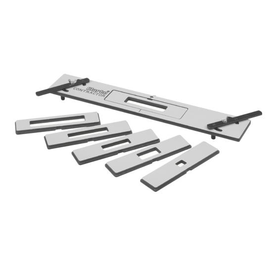
- Page 5 Jig Assembly The only assembly required is to attach the centralising levers, this is carried out as follows: 1. With the Clarke logo in the nesting plate facing upwards, insert the lever prongs into the plate slots (Fig. 1). 2. Fit nylon spacer between the lever and nesting plate (Fig. 2) 3.
- Page 6 Using the Jig Depending on the size of lock to be fitted etc, all that is required is to mark on the door edge the centre line of the lock position. As a general guideline the centre line would normally be 1 metre from the bottom of the door. Fig.
- Page 7 Select the correct pair of inserts for the lock to be fitted. Fit the Insert with the largest aperture (lock plate) into the nesting plate and secure in Fig. 7 Fig. 7a place with locking screw (Fig. 7 & 7a), ensure the insert sits flat in the nesting plate.
Need help?
Do you have a question about the CONTRACTOR CLJ120 and is the answer not in the manual?
Questions and answers