
Related Manuals for SMC Networks MHK2-12 Series


Summary of Contents for SMC Networks MHK2-12 Series
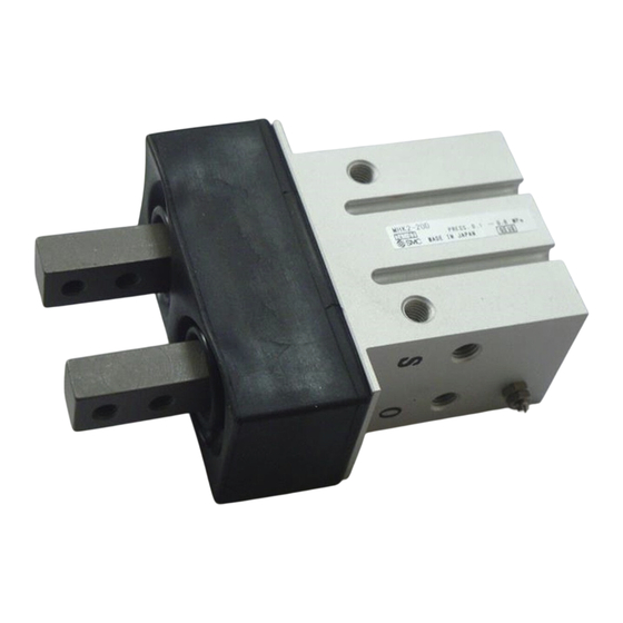
- Page 1 Doc.No.MH*-OMF0058 PRODUCT NAME Wedge cam operation slide guide Air gripper MODEL / Series / Product Number MHK2-12* MHK2-16* MHK2-20* MHK2-25* MHKL2-12* MHKL2-16* MHKL2-20* MHKL2-25*...
-
Page 2: Table Of Contents
Contents Safety instructions 1. Product specifications ......................5 1-1. Specifications ........................5 2.Operating method or operation ....................6 2-1. Design precautions ....................... 6 2-2. Selection ..........................6 2-3. Installation ..........................8 2-4.Piping ..........................14 2-5. Lubrication.......................... 14 2-6. Air supply ........................... 14 2-7. -
Page 3: Safety Instructions
Safety Instructions These safety instructions are intended to prevent hazardous situations and/or equipment damage. These instructions indicate the level of potential hazard with the labels of “Caution,” “Warning” or “Danger.” They are all important notes for safety and must be followed in addition to International Standards (ISO/IEC)*1) , and other safety regulations. - Page 4 Safety Instructions Caution The product is provided for use in manufacturing industries. The product herein described is basically provided for peaceful use in manufacturing industries. If considering using the product in other industries, consult SMC beforehand and exchange specifications or a contract if necessary. If anything is unclear, contact your nearest sales branch.
-
Page 5: Product Specifications
1. Product specifications 1-1. Specifications Max.Operating Opening /closing Closed dia. Open dia. Action Model Mass Bore Size frequency stroke c.p.m. MHK2-12D Double MHK2-16D 14.6 20.6 acting MHK2-20D MHK2-25D MHK2-12S MHK2-16S 14.6 20.6 MHK2-20S Single MHK2-25S acting MHK2-12C MHK2-16C 14.6 20.6 MHK2-20C MHK2-25C MHKL2-12D... -
Page 6: Operating Method Or Operation
2.Operating method or operation 2-1. Design precautions Warning 1. The product is designed for use only in compressed air systems. Do not operate at pressures or temperatures, etc., beyond the range of specifications, as this can cause damage or malfunction. (Refer to the specifications.) Please contact SMC if using for fluids other than compressed air. - Page 7 3. Attachments should be designed to be as light and short as possible. (1) A long or heavy attachment increases the inertia force required to open or close the fingers. This may cause unsteady movement of fingers and have an adverse affect on the life of the gripper.
-
Page 8: Installation
2-3. Installation Warning 1. Install and operate the product only after reading the Operation Manual carefully and understanding its contents. Also, keep the manual where it can be referred to as necessary. 2. Allow sufficient space for maintenance and inspection. 3. - Page 9 Vertical mounting(Body tapped) Max. Maximum tightening screw-in Model Screw depth (L mm) torque (N・m) MHK2-12□ 0.59 M3x0.5 MHKL2-12□ 0.74 MHK2-16□ 0.88 M4x0.7 MHKL2-16□ MHK2-20□ M5x0.8 MHKL2-20□ MHK2-25□ M6x1 MHKL2-25□ Side mounting (Body tapped) Maximum Max. screw-in tightening Model Screw depth torque(N・m) (L mm) MHK2-12□...
- Page 10 1. Stroke end when fingers are opened Impact load With clearance Without clearance 2. Stroke end when gripper is moving Impact load 〇 With clearance ✕ Without clearance 3.When turning over Inversion Impact load...
- Page 11 3. Adjust the gripping point so that an excessive force will not be applied to the fingers when inserting a workpiece. Confirm that the gripper can operate without receiving any shock by testing it in manual operation mode or by low speed operation. Impact load Not good: No clearance Good: With clearance...
- Page 12 6. Auto Switch Hysteresis Auto switches have hysteresis similar to micro switches. Use the table below as a guide when adjusting auto switch positions, etc. Max.hysteresis(mm) D-M9□(v) D-M9□A(v) M9□W(v) Air gripper MHK□2-12 MHK□2-16 MHK□2-20 MHK□2-25 7. Protrusion of Auto Switch from Edge of Body •...
- Page 13 1)Confirmation of fingers in 2)Confirmation of workpiece Detection example reset position released Position of fingers fully opened Position of fingers fully closed Position to be detected When a workpiece is not held Auto switch turned ON when Operation of auto switch (Abnormal operation): Auto fingers return.
-
Page 14: 2-4.Piping
2-4.Piping Caution 1. Refer to the Fittings and Tubing Precautions (Best Pneumatics) for handling one touch fittings. 2. Before piping Before piping is connected, flush thoroughly with air or wash to remove chips, cutting oil and other debris from inside the pipe. 2-5. -
Page 15: Maintenance
4. Do not mount the product in locations where it is exposed to radiant heat. 5. Do not use this product in an area that is dusty, or in an environment in which water or oil splashes on the cylinder. 3. -
Page 16: Exploded View
Doc.No.MH*-OMF0058 3-2. exploded view Dust cover Rod packing Finger Body O ring Needle Piston ASSY Piston packing Piston bolt O-ring for piston bolt O ring Type C retaining ring... -
Page 17: Replacement Procedure
3-3. Replacement Procedure 1). Remove the C-shaped retaining ring 3). Remove the dust cover. with the prescribed tool and remove the cap. Type C retaining ring Dust cover 2). Remove the piston bolt. 4). Open the fingers and remove the cam. hexagonal wrench Finger... -
Page 18: Component Parts/Replacement Parts
3-4. Component Parts/Replacement Parts Components Description Material Note Hard anodized Body Aluminum alloy Hard anodized Piston Aluminum alloy Carbon steel Heat treated, Specially treated Carbon steel Heat treated, Specially treated Finger Stainless steelSUS304 Option Hard anodized Aluminum alloy Piston bolt Stainless steel Lever magnet Synthetic rubber... - Page 19 Description Material Note Lod packing Piston packing Gasket Gasket Dust cover Silicone rubber MHK2 replacement parts Main Description MHK2-12□ MHK2-16□ MHK2-20□ MHK2-25□ parts Packing set ⑯⑰⑱⑲ MHK12-PS MHK16-PS MHK20-PS MHK25-PS Piston ASSY ②⑥⑦ MHK-A1201 MHK-A1601 MHK-A2001 MHK-A2501 ③ P3318103 P3318203 P3318303 P3318403 Carbon steel...
- Page 20 Revision history 1. Layout change 4-14-1, Sotokanda, Chiyoda-ku, Tokyo 101-0021 JAPAN Tel: + 81 3 5207 8249 Fax: +81 3 5298 5362 https://www.smcworld.com Note: Specifications are subject to change without prior notice and any obligation on the part of the manufacturer. ©...
Need help?
Do you have a question about the MHK2-12 Series and is the answer not in the manual?
Questions and answers