Table of Contents
Advertisement
Advertisement
Table of Contents

Related Manuals for SIG Somethin' EXTRA N477SC


Summary of Contents for SIG Somethin' EXTRA N477SC
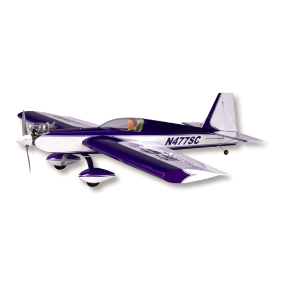
- Page 2 When the model is set-up as suggested in these instructions, you will have an airplane that simply does it all! If you have been looking for a design that is fully up to your flying skills, then the SIG SOMETHIN EXTRA was designed and engineered just for you.
- Page 3 Debonder (SIGCA040) available during the construction of this model. One of the fuselage construction steps will call for the use of aliphatic resin glue, such as our SIG-Bond product SIGSB001. The only epoxy glue that you will need to build this design is SIG Kwik-Set 5-minute Epoxy Glue, SIGKS001.
- Page 4 Landing Gear & Motor Mount Control Horn Attach Attach 6 #6 Metal Washers - Wheel Axle 1 Piece of 1"x8" Fiberglass Tape 18 SIG Easy Hinges - Ailerons (8), Assembly Elevators (6), Rudder (4) Miscellaneous Parts 1 7/8 O.D. x15-1/4" Aluminum Tube - 1 .880 I.D.
- Page 5 Cover the top surface of your building board with a large piece of "Celotex" or even foam insulation board, which will easily accept pins. Be sure to use plenty of pins or weights when building in order to hold assemblies firmly in place. When building over full-size plans, always protect them with wax paper to prevent glue damage and parts sticking to the plans themselves.
-
Page 7: Wing Construction
WING CONSTRUCTION Note: The full size plan depicts both right and left wing panels from the TOP view. These wing panels are initially built directly over the plans and are not removed for the bottom sheeting until Step 12. These instructions assume you are building both wing panels at the same time. - Page 8 Remove the weights, wing sheeting and top spar from the wing structure. Slip the previously made female wing tube receptacle in place through W-1A and W-2, leaving 1/8" exposed at the outer face of W-1A - do not glue in place yet. From the contents of your kit, locate the ten (10) pieces of 3/32"x1-3/4"x4"...
- Page 9 11. The two (2) pieces of 1/16"x4"x24" balsa sheet stock provided in your kit are now used to make the center section sheeting for both the top and bottom of both wing panels. Begin by using a straightedge to slice the edges of these sheets exactly straight.
- Page 10 14. IMPORTANT: Note that with the bottom sheeting not in place, the wing panels are not yet rigid and may be easily twisted. Once the bottom sheeting is in place, the panels are essentially locked in shape. Therefore, it is very important to properly support the wing panels during this step.
- Page 11 20. Remove the completed ailerons from your work surface. Both ailerons should now be sanded smooth. Use a long T-bar sanding tool and 80 grit sandpaper to smooth both sides and the leading and trailing edges of each aileron (80 grit cuts quickly, so don t over do it).
- Page 12 This is easy to do using a hobby knife and a #11 blade. A Dremel Tool and a carbide cut-off wheel may also be useful in this step. Once the elevator halves are grooved, trial fit them together with the wire joiner. Adjust the grooves and holes as required to achieve a good fit.
- Page 13 34. Using the fiberglass tape provide in your kit, cut four 1/2"x3/4" pieces. These are glued in place over the rudder and elevator control horn holes with thin CA glue. Next, cut two pieces of fiberglass tape to fold over each of the elevator/joiner wire joints, as shown on the plans, again using thin CA glue.
-
Page 14: Fuselage Construction
Therefore, we suggest that you use a slower setting glue, such as an aliphatic resin like the SIG-Bond product. Using this glue gives plenty of time to position parts correctly. Start by fitting these parts together to see how they relate to each other - again make sure you are working with a LEFT and RIGHT fuselage side and doubler. - Page 15 46. Glue the 1/8" ply tank floor in place to the fuselage sides, the back face of F-1 and the front face of F-2. Using the 1/8"x1/4"x36" balsa stock in your kit, cut a 3" length. This piece is now glued into the slots in the doublers, on the bottom of the fuselage, beneath the tank tray.
- Page 16 52. Remove the 1/4"x1/2" spacer from the rear of the fuselage. The Fuselage Bottom part FB-3 is now glued in place. First feed the nylon antenna tube through the slot in the rear of the part. Fit FB-3 in place, securing it firmly to the fuselage sides with tape.
- Page 17 Access to the tank is easy if you use filament strapping tape to create a rear tab that allows you to grasp it and pull the tank out if needed. To do this, use alcohol to first clean the outside of the tank. Then wrap the length of the tank one or two times with strapping tape.
- Page 18 65. Remove the tape and remove the canopy hatch assembly from the fuselage. Apply glue to the unrounded end of the 1/8" dia. dowel prepared earlier and insert it into the back face of the Canopy Hatch former, flush with the front face. Set the glue and sand the front of the former smooth with a small sanding block.
- Page 19 70. Use a razor plane or hobby knife to roughly carve the fairing blocks to match the lines of the fuselage. Use 80 grit sandpaper to further shape the fairing blocks to the cross section shape shown on the plans. When the shape is close, use 220 grit sandpaper to sand the rear stringer area and the fairing blocks smoothly together.
- Page 20 To minimize weight and enjoy the full potential of this model, it should be covered in a good quality, light-weight iron-on film, such as SIG Supercoat covering products. If you intend to use two contrasting colors, you will require at least two rolls of covering material - typically one for the base color and the other for the trim color.
- Page 21 Allow the resin to cure and sand it lightly. You can now paint the engine compartment with a complimentary color for your covering scheme or simply use flat black or white SIG Butyrate Dope.
-
Page 22: Final Assembly
Installing Easy Hinges SIG s famous Easy Hinges have been included with your kit to hinge all the control surfaces. Each ultra-thin hinge is actually a three-part laminate - a tough plastic inner core sandwiched by an absorbent wicking material. They have been chemically treated to slow down the reaction of thin CA glue (normally instant), to allow the glue time to soak all the way to the ends of the hinge and into the surrounding wood. - Page 23 b. With the tailwheel in place, the rudder can now be hinged to the vertical fin and fuselage. Follow the directions given in the INSTALLING EASY HINGES section. Tail Supports The tail support system used on the Somethin Extra provides an added measure of support and rigidity to the stab and fin. As it does for full scale aerobatic aircraft, this system allows the model to be flown through extremely violent maneuvers without being concerned with the integrity of the tail group.
- Page 24 You can use almost any kind of fuel proof paint to finish the pants. We have used and can recommend paints such as SIG Supercoat dope and "K&B" epoxy. i. The finished wheel pants can now be mounted to the landing gear with the 4-40 x3/8" bolts. We suggest using a thread locking material to eliminate vibration problems (such as "Loctite"...
-
Page 25: Radio Installation
Engine And Tank Installation 87. With the tank compartment and fuel tank already prepared for installation (FUSELAGE CONSTRUCTION, Step 58a,b), the tank is now installed. Use a single 20" length of medium fuel tubing, folded in half. Insert the two 10" loose ends through the oblong hole in the front of the firewall and retrieve them through the tank compartment at F-2. - Page 26 Thread one of the nylon R/C links onto the remaining threads, roughly centering it on the threads for later adjustments. This prepared end will be located at the control surface (rudder or elevator). 91. Prepare the two remaining 10" metal pushrods by cutting 8-3/4"...
- Page 27 There are any number of different radio systems currently in use and on the market. Because of this, it is not possible to explain the optimum set-up of all these systems for this particular model. The following suggested control surface travel information is based upon our experience with the Somethin Extra.
- Page 28 Center Of Balance Like all R/C models, the Somethin Extra was designed to be flown with the proper Center of Balance (or CG). As shown on the plans, the CG falls exactly in the center of the 1/4" wing spar, or 3-1/2" back from the leading edge. As previously mentioned, this design allows for a relatively huge shift in the location of the airborne battery pack.
-
Page 29: Customer Service
Customer Service SIG MFG. CO. is totally committed to your success in both building and flying the SOMETHIN EXTRA design. Should you encounter any problem building this kit, or discover any missing or damaged parts, please feel free to contact us by mail or telephone.
Need help?
Do you have a question about the Somethin' EXTRA N477SC and is the answer not in the manual?
Questions and answers