Table of Contents
Advertisement
Quick Links
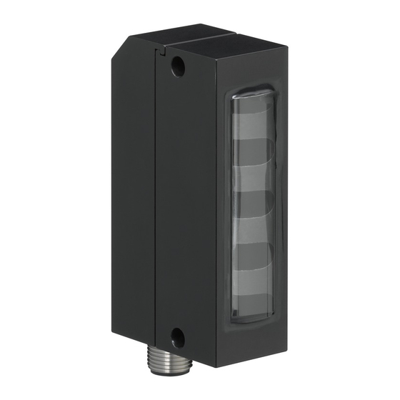
AKS 171.2
300 ... 1700 mm
IP 54
Gapless detection of the smallest parts
through automatic adjustment in the range
of 60 mm (in front of transmitter)
4-step switch for adaptation to the size of the
ejected goods (receiver)
Optimum adaptation of the transmitting
power by means of an infinitely adjustable
potentiometer (transmitter)
Exact, time-saving alignment though indica-
tor LEDs – bar graph – and variation of the
transmitting power
Static and dynamic monitoring in the range
between 300 ... 1700 mm
Static detection of parts that were left
behind
Warning output if reception signal is too low
Compact design in metal construction.
Accessories:
(available separately)
Cables with M12 connector (KD ...)
Leuze electronic GmbH + Co. KG
info@leuze.com • www.leuze.com
Dimensioned drawing
A
Receiver:
B
LEDs
C
Protection cap for receiver, screw type
Electrical connection
Transmitter
In der Braike 1 D-73277 Owen Tel. +49 (0) 7021 573-0
4-step switch (adaptation to the thickness of the parts)
Receiver
Ejection monitoring
AKS 171.2... - 01
Advertisement
Table of Contents

Related Manuals for Leuze electronic AKS 171.2


Summary of Contents for Leuze electronic AKS 171.2
- Page 1 Compact design in metal construction. Accessories: Electrical connection (available separately) Cables with M12 connector (KD …) Transmitter Receiver Leuze electronic GmbH + Co. KG In der Braike 1 D-73277 Owen Tel. +49 (0) 7021 573-0 AKS 171.2… - 01 info@leuze.com • www.leuze.com...
- Page 2 8 V / 2 V or not connected Transmitter inactive/active 0.5 ms Activation/disable delay SYNC Not connected 1) Operating range: recommended range with function reserve 2) 1=transient protection, 2=polarity reversal protection, 3=short circuit protection for all outputs AKS 171.2… - 01 2018/11...
- Page 3 Set consisting of transmitter (50138388) and receiver (50138389) SET AKS 171.2/4.5.1-S12 50140950 Alignment - Setting Device overview The AKS 171.2 sensor system is a fast, high-resolution light curtain consisting of transmitter and receiver: AKS 171.2 transmitter AKS 171.2 receiver (with mounted protection cap, 15 mm deep) Note! Prerequisite for optimum function of the system is the proper alignment and adjustment of transmitter and receiver as described in the following.
- Page 4 - 1 LED on weak reception signal ⑧ - 0 LEDs on very weak or no reception signal Red LED - Illumination indicator ⑧ 2 states: - On: uneven illumination - Off: even illumination (rest state) AKS 171.2… - 01 2018/11...
- Page 5 3) If a sensor is mounted too high, the objects that are to be detected may fall below the detection range; if a sensor is mounted too low, parts could jump out of the detection range. Leuze electronic GmbH + Co. KG In der Braike 1 D-73277 Owen Tel. +49 (0) 7021 573-0 AKS 171.2…...
- Page 6 8. Now also tighten the X-axis of the transmitter so that it is immovable, whereby the ascertained alignment position must not be changed from this point on. Note! The accuracy of the alignment is essential for the detection of small parts and for the insensitivity of the sys- tem with respect to physical shocks. AKS 171.2… - 01 2018/11...
- Page 7 1) Large object = light path is fully or largely darkened. Leuze electronic GmbH + Co. KG In der Braike 1 D-73277 Owen Tel. +49 (0) 7021 573-0 AKS 171.2… - 01 info@leuze.com • www.leuze.com...
- Page 8 ⑧ Illumination indicator illuminates if Receiver defective Exchange device if necessary and send to manu- receiver optics are fully shaded or if facturer for repair. transmitter is inactive AKS 171.2… - 01 2018/11...
Need help?
Do you have a question about the AKS 171.2 and is the answer not in the manual?
Questions and answers