Sign In
Upload
Manuals
Brands
Bender Manuals
Measuring Instruments
AGH675S-7
Bender AGH675S-7 Coupling Measuring Manuals
Manuals and User Guides for Bender AGH675S-7 Coupling Measuring. We have
2
Bender AGH675S-7 Coupling Measuring manuals available for free PDF download: Manual
Bender AGH675S-7 Manual (76 pages)
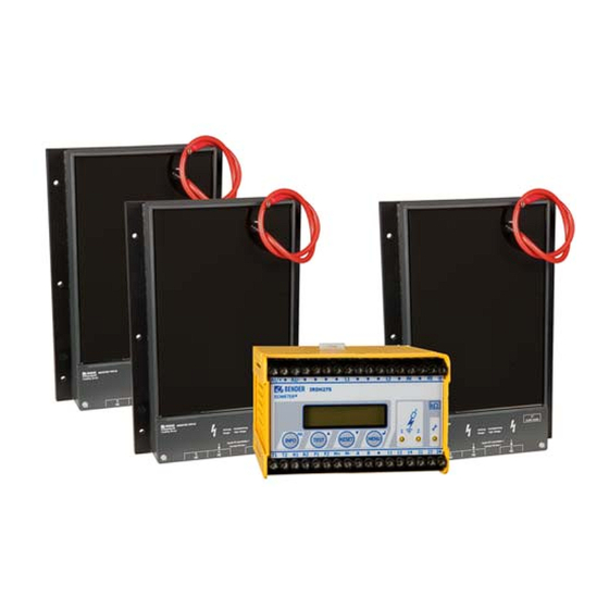
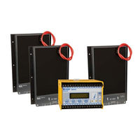
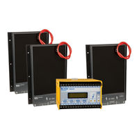
Insulation monitoring device for medium voltage, Coupling device
Brand:
Bender
| Category:
Measuring Instruments
| Size: 1 MB
Table of Contents
Table of Contents
3
1 Important Information
7
How to Use this Manual
7
Technical Support: Service and Support
8
First Level Support
8
Repair Service
8
Field Service
9
Training Courses
9
Delivery Conditions
9
Inspection, Transport and Storage
10
Warranty and Liability
10
Disposal
11
2 Safety Instructions
12
General Safety Instructions
12
Work Activities on Electrical Installations
12
Device-Specific Safety Information
13
Intended Use
15
Directions for Installation
16
3 Function
18
Characteristics IRDH275BM-7 Incl. AGH675S-7
18
Product Description
19
Function
19
4 Installation and Connection
24
Installation of the Coupling Device AGH675S-7
24
Wiring Diagram
25
5 Operation and Setting
30
Operating Features and Displays IRDH275BM-7
30
Display in the Standard Mode
31
Display in the Menu Mode
31
Function Keys
32
Menu Structure and Menu Mode
34
Diagram Menu Structure
35
Menu HISTORY INFO
36
Diagram HISTORY INFO
37
Menu ISO SETUP: Setting of the Basic ISOMETER® Functions
38
Response Values Alarm 1 and Alarm 2
38
Operating Principle of the Alarm Relays
39
Memory Setting (On/Off)
41
Current Output for External Measuring Instruments
41
Menu ISO ADVANCED: Setting of the Extended Functions
42
Coupling Devices AGH: 675S-7
42
Adaptation to the System Leakage Capacitance Cemax
42
Measuring Principle (Measure: AMP)
42
Setting the Repetition Time for Automatic Self Tests
42
(Autotest: 24H)
42
Setting the Real-Time Clock (Clock)
42
Setting the Date (Date)
43
Specifying the Starting Time of the Automatic Self Test (Test) (IRDH275B)
43
Diagram ISO ADVANCED
44
Menu COM SETUP: Setting the BMS Interface
45
Bus Address „Addr
45
Diagram COM SETUP
46
Menu PASSWORD
47
Activating and Setting the Password
47
Diagram PASSWORD
48
Menu LANGUAGE
49
Setting the National Language
49
Diagram Language
49
Menu SERVICE
50
Parameterization Via Internet
50
6 Serial Interfaces
51
RS-485 Interface with BMS Protocol
51
Topology RS-485 Network
52
Correct Arrangement
52
Wrong Arrangement
52
Wiring
52
BMS Protocol
53
BMS Master
53
BMS Slave
54
Commissioning of an RS-485 Network with BMS Protocol
55
7 Technical Data IRDH275BM-7 with AGH675S-7
57
Data in Tabular IRDH275BM-7
57
Serial Interface
58
Standards and Approvals
60
Data in Tabular AGH675S-7
61
Data in Tabular AGH675S-7MV15
63
Characteristic Curves
65
Ordering Details
70
ISOMETER® and Coupling Devices
70
Advertisement
Bender AGH675S-7 Manual (40 pages)
Insulation monitoring device for medium voltage IT systems with galvanically connected rectifiers and converters up to AC/DC 15.5 kV
Brand:
Bender
| Category:
Measuring Instruments
| Size: 3 MB
Table of Contents
Table of Contents
3
1 General Instructions
5
How to Use this Manual
5
Indication of Important Instructions and Information
5
Signs and Symbols
5
Training Courses and Seminars
5
Delivery Conditions
5
Inspection, Transport and Storage
5
Warranty and Liability
6
Disposal of Bender Devices
6
Safety
6
Device-Specific Safety Information
6
Intended Use
7
Directions for Installation
7
2 Function
9
Characteristics IRDH275BM-7 Incl. AGH675S-7
9
Product Description
9
Function Description
10
3 Dimensions, Installation and Connection
12
Dimension Diagrams
12
Mounting IRDH275
12
Installation of the Coupling Device AGH675S-7
12
Wiring Diagrams (by Way of Example)
13
4 Operation and Setting
16
Operating Features and Displays IRDH275BM-7
16
Display in the Standard Mode
16
Display in the Menu Mode
17
Function Keys
17
Menu Structure and Menu Mode
18
Diagram Menu Structure
19
Menu HISTORY INFO
19
Diagram HISTORY INFO
20
Menu ISO SETUP: Setting of the Basic ISOMETER® Functions
21
Response Values Alarm 1 and Alarm 2
21
Operating Principle of the Alarm Relays
21
Diagram ISO SETUP
22
Memory Settings (On/Off)
22
Current Output for External Measuring Instruments
23
Menu ISO ADVANCED: Setting of the Extended Functions
23
Coupling Devices AGH: 675S-7
23
Adaptation to the System Leakage Capacitance C E Max
23
Measuring Principle (Measure: AMP)
23
Setting the Repetition Time for Automatic Self Tests (Autotest: 24H)
23
Setting the Real-Time Clock (Clock)
23
Setting the Date (Date)
24
Specifying the Starting Time of the Automatic Self Test (Test)
24
Diagram ISO ADVANCED
24
Menu COM SETUP: Setting the BMS Interface
25
Bus Address „Addr
25
Diagram COM SETUP
25
Menu PASSWORD
26
Activating and Setting the Password
26
Diagram PASSWORD
26
Menu LANGUAGE
26
Setting the National Language
26
Diagram Language
27
Menu SERVICE
27
Parameterization Via Internet
27
5 Serial Interfaces
28
RS-485 Interface with BMS Protocol
28
Topology RS-485 Network
28
Correct Arrangement
28
Wrong Arrangement
29
Wiring
29
BMS Protocol
29
BMS Master
29
BMS Slave
30
Commissioning of an RS-485 Network with BMS Protocol
31
6 Technical Data IRDH275BM-7 with AGH675S-7
32
Data in Tabular IRDH275BM-7
32
Data in Tabular AGH675S-7
34
Data in Tabular AGH675S-7MV15
35
Characteristic Curves
36
Standards and Approvals
38
Ordering Details
38
Advertisement
Related Products
Bender AGH675S-7MV15
Bender AGH421
Bender AF460
Bender AG410
Bender ISOMETER AGH420-1
Bender A-ISOMETER AGH575S-6
Bender A-ISOMETER IRDH375
Bender A-ISOMETER IRDH375B
Bender AGH421-1
Bender AGH420
Bender Categories
Measuring Instruments
Monitor
Control Unit
Control Panel
Relays
More Bender Manuals
Login
Sign In
OR
Sign in with Facebook
Sign in with Google
Upload manual
Upload from disk
Upload from URL