Table of Contents
Advertisement
Quick Links
Handbuch/Manual
ISOMETER® IR420-D4
Isolationsüberwachungsgerät
Bestimmungsgemäße Verwendung
®
Das ISOMETER
IR420 überwacht den Isolationswiderstand R
geerdeter AC-Steuerstromkreise (IT-System) von 0...300 V. Enthal-
ten die zu überwachenden IT-Systeme Gleichspannungs-
komponenten, kommt es im DC-Fehlerfall zu Verfälschungen im
Anzeige- und Ansprechverhalten. Die zulässige Netzableitkapazi-
tät C
max beträgt 20 μF.
e
Sicherheitshinweise allgemein
Dieses Handbuch richtet sich an Fachpersonal der
Elektrotechnik und Elektronik! Bestandteil der Gerä-
tedokumentation sind neben diesem Datenblatt
die beiliegenden „Wichtigen sicherheits-techni-
schen Hinweise für Bender-Produkte".
Lebensgefahr durch Stromschlag!
Nicht fachgerecht durchgeführte Arbeiten an elekt-
rischen Anlagen können zu Gefahren für Gesund-
heit und Leben führen! Alle erforderlichen Arbeiten
zum Einbau, zur Inbetriebnahme und zum laufen-
GEFAHR
den Betrieb des Gerätes oder Systems sind durch ge-
eignetes Fachpersonal auszuführen.
Sicherheitshinweise gerätespezifisch
Gefahr vor Sachschaden durch
unsachgemäße Installation!
Die Anlage kann Schaden nehmen, wenn Sie in
einem leitend verbundenen System mehr als ein Iso-
lationsüberwachungsgerät anschließen. Sind meh-
rere Geräte angeschlossen, funktioniert das Gerät
VORSICHT
nicht und meldet keine Isolationsfehler. Schließen
Sie in jedem leitend verbundenen System nur ein
Isolationsüberwachungsgerät an.
Trennung vom IT-System beachten!
Vor Isolations- und Spannungsprüfungen an der An-
lage muss das Isolationsüberwachungsgerät für die
Dauer der Prüfung vom IT-System getrennt sein. An-
VORSICHT
dernfalls kann das Gerät Schaden nehmen.
Bei einer Alarmmeldung des ISOMETER®s sollte der
Isolationsfehler schnellstmöglich beseitigt werden.
Die Meldung des ISOMETER®s muss auch dann akus-
tisch und/oder optisch wahrnehmbar sein, wenn das
Gerät innerhalb eines Schaltschrankes installiert ist.
Funktionsbeschreibung
®
Das ISOMETER
IR420 erzeugt eine Messgleichspannung. Diese
wird über die Klemmen L1/L2 und KE/E dem zu überwachenden IT-
System überlagert. Ohmsche Isolationsfehler zwischen IT-System
und Erde schließen den Messkreis. Der aktuelle gemessene Isolati-
onswiderstand wird auf dem Display des Geräts angezeigt.
Preset-Funktion
Nach erstem Anlegen der Versorgungsspannung U
peltem IT-System werden die Ansprechwerte R
einmalig automatisch auf folgende Werte gesetzt:
IR420-D4_D00037_02_M_DEEN / 07.2016
Insulation monitoring device
Intended use
un-
The IR420 ISOMETER
F
earthed AC control circuits (IT system) of AC 0...300 V. If the IT sys-
tems to be monitored include DC components and a DC fault
occurs, the operating and display characteristics will be affected.
The maximum permissible system leakage capacitance C
Safety instructions
DANGER
Device-specific safety information
CAUTION
CAUTION
Function
The IR420 ISOMETER
superimposed on the IT system being monitored via the terminals
L1/L2 and KE/earth. Ohmic insulation faults close the measuring cir-
cuit between the IT system and earth. The currently measured insu-
lation resistance is shown on the display of the device.
Preset function
und angekop-
After connecting the supply voltage U
S
/R
(Alarm 1/2)
tem for the first time, the response values R
an1
an2
automatically set once to:
®
monitors the insulation resistance of un-
This manual is intended for qualified personnel
working in electrical engineering and electronics!
In addition to this data sheet, the documentation of
the device includes a sheet entitled "Important safe-
ty instructions for Bender products".
Risk of fatal injury from electric shock!
Any work on electrical installations which is not car-
ried out properly can lead to death and injury!
Only skilled persons are permitted to carry out the
work necessary to install, commission and run a de-
vice or system.
Risk of property damage due to
unprofessional installation!
If more than one insulation monitoring device is
connected to a conductively connected system, the
system can be damaged. If several devices are con-
nected, the device does not function and does not
signal insulation faults. Make sure that only one in-
sulation monitoring device is connected in each
conductively connected system.
Ensure disconnection from the IT system!
When insulation or voltage tests are to be carried
out, the device shall be isolated from the system for
the test period. Otherwise the device may be dam-
aged.
In the event of an alarm message, the insulation
fault should be eliminated as quickly as possible.
If the ISOMETER® is installed inside a control cabi-
net, the insulation fault message must be audible
and/or visible to attract attention.
®
generates a DC measuring voltage which is
and connecting the IT sys-
S
an1
is 20 μF.
e
/R
(Alarm 1/2) are
an2
1
Advertisement
Table of Contents

Related Manuals for Bender ISOMETER IR420-D4


Summary of Contents for Bender ISOMETER IR420-D4
- Page 1 In addition to this data sheet, the documentation of die beiliegenden „Wichtigen sicherheits-techni- the device includes a sheet entitled "Important safe- schen Hinweise für Bender-Produkte“. ty instructions for Bender products". Lebensgefahr durch Stromschlag! Risk of fatal injury from electric shock! Nicht fachgerecht durchgeführte Arbeiten an elekt- Any work on electrical installations which is not car- rischen Anlagen können zu Gefahren für Gesund-...
- Page 2 ISOMETER® IR420-D4 > 72 V: Ansprechwert 1 = 46 kΩ, Ansprechwert 2 = 23 kΩ > 72 V: response value 1 = 46 kΩ, response value 2 = 23 kΩ ≤ ≤ 72 V: Ansprechwert 1 = 20 kΩ, Ansprechwert 2 = 10 kΩ 72 V: response value 1 = 20 kΩ, response value 2 = 10 kΩ...
- Page 3 ISOMETER® IR420-D4 clip erforderlich, siehe Bestellinformation) mittels Werk- ing clip required, see ordering details) into a position that zeug in eine über das Gehäuse hinaus ragende Position. it projects beyond the enclosure. Then fix the device using Befestigen Sie danach das Gerät mit zwei M4-Schrauben. two M4 screws.
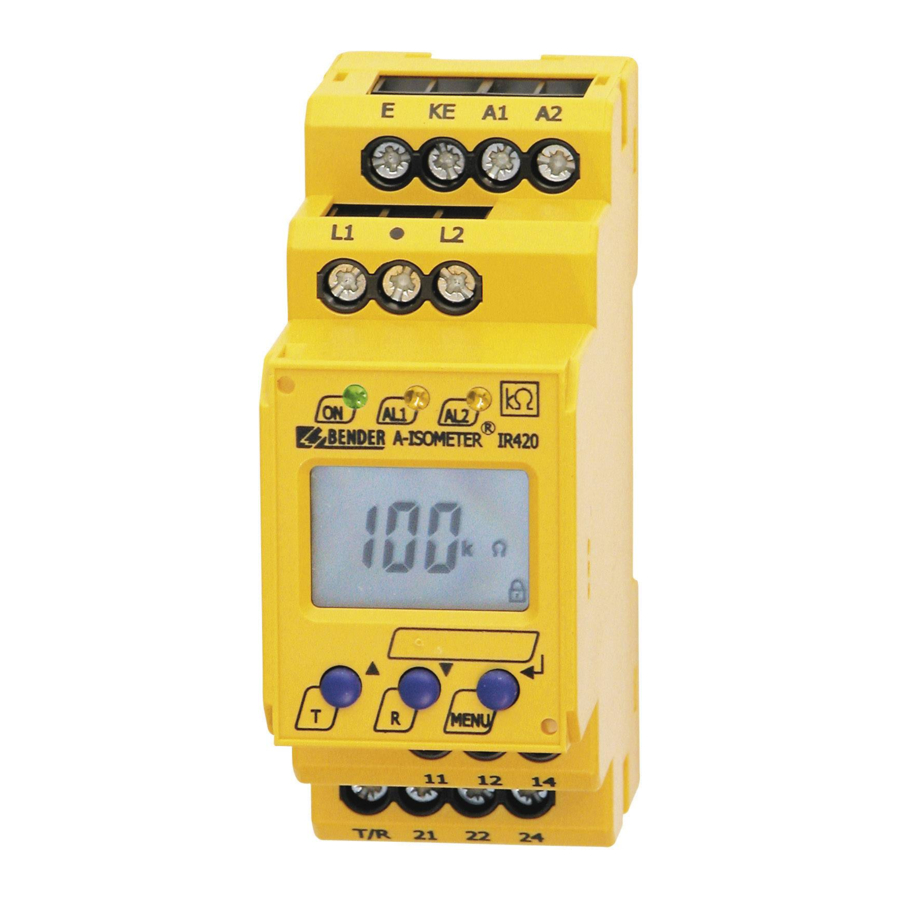
- Page 4 ISOMETER® IR420-D4 Ele- Gerätefront/ Ele- Funktion Function ment Front of the device ment Betriebs-LED, grün Power ON LED, green LED Alarm 1 leuchtet( gelb): LED Alarm 1 lights ( yellow): AL1, Ansprechwert 1 unterschritten AL1, value below response value 1 AL1 AL2 LED Alarm 2 leuchtet (gelb): LED Alarm 2 lights (yellow):...
- Page 5 ISOMETER® IR420-D4 Einstellen der Parameter Parameter settings Beispielhaft wird die Änderung des Alarm-Ansprechwerts R An example is given below on how to change the alarm response (R 2) beschrieben. So gehen Sie vor: value R (R 2). Proceed as follows: Drücken Sie die Taste MENU/Enter länger als 1,5 s.
- Page 6 ISOMETER® IR420-D4 Verzögerungszeiten einstellen Setting the time delay Hiermit können Sie eine Ansprechverzögerung t (0…99 s) so- Use this segment to enter the response delay t (0…99 s) and wie eine Anlaufverzögerung t (0…10 s) vorgeben the starting delay t (0…10 s). Reset to factory setting and password protection Werkseinstellung herstellen und Passwort-Schutz Mit Hilfe dieses Menüs können Sie den Passwort-Schutz einschal-...
- Page 7 ISOMETER® IR420-D4 Technische Daten IR420-D4.. Technical data IR420-D4.. Isolationskoordination nach IEC 60664-1/IEC 60664-3 Insulation coordination acc. to IEC 60664-1/IEC 60664-3 Bemessungsspannung ......................250 V Rated insulation voltage......................250 V Bemessungs-Stoßspannung / Verschmutzungsgrad ............4 kV / 3 Rated impulse voltage / Pollution degree................4kV / 3 Sichere Trennung (verstärkte Isolierung) zwischen: Protective separation (reinforced insulation) between: ...............
- Page 8 Genehmigung des Herausgebers. only with permission of the publisher. Änderungen vorbehalten! Subject to change! © © Bender GmbH & Co. KG Bender GmbH & Co. KG Bender GmbH & Co. KG Tel.: +49 6401 807-0 E-Mail: info@bender.de •...
Need help?
Do you have a question about the ISOMETER IR420-D4 and is the answer not in the manual?
Questions and answers