
Subscribe to Our Youtube Channel
Related Manuals for Woodward XRI1-IR


Summary of Contents for Woodward XRI1-IR
- Page 1 XRI1-IR – Digital multifunctional relay for time overcurrent protection Manual XRI1-IR (Revision C)
- Page 2 Woodward Manual XRI1-IR Woodward reserves the right to update any portion of this publication at any time. Information provided by Woodward is believed to be correct and reliable. However, no responsibility is assumed by Woodward unless otherwise expressly undertaken. © Woodward 1994–2019...
-
Page 3: Table Of Contents
Definite time overcurrent element ...................... 26 6.2.2 Inverse time overcurrent element ...................... 27 Indication of measuring and fault values ....................27 6.3.1 Measuring values ..........................27 6.3.2 Indication of fault data ........................27 6.3.3 Fault recorder............................. 28 Reset ..............................29 DOK-TD-XRI1-IR, Rev. C... - Page 4 Checking the set values ......................... 30 Secondary injection test ......................... 31 7.4.1 Test equipment ..........................31 7.4.2 Test circuit of XRI1-IR ........................31 7.4.3 Checking the input circuits and measured values ................33 7.4.4 Checking the operating and resetting values of the relay ..............33 7.4.5...
-
Page 5: Introduction And Application
Woodward 1. Introduction and application The digital relay type XRI1-IR as time overcurrent protection has been designed for the use in electrical ma- chines, lines and grids. The protective functions of XRI1-IR that are implemented in only one device are summarized as follows: ... -
Page 6: Features And Characteristics
Storage of tripping values and shut-down times of eight failure events Free assignment of output relays Serial data exchange via RS485 interface possible with Woodward RS485-Pro Open Data Protocol Suppression of indication after an activation (LED flash) -
Page 7: Design
Woodward 3. Design Connections Figure 3.1: Connection diagram XRI1-IR 3.1.1 Analog input circuits The protection unit receives the analog input signals of the phase currents IL1 (1S1-1S2), IL2 (2S1-2S2), IL3 (3S1-3S2), phase voltages U1 (L1-N1), U2 (L2-N2), U3 (L3-N3) each via separate input transformers. The N1, N2 and N3 are bridged externally. -
Page 8: Output Relays (Default Settings)
Woodward Manual XRI1-IR 3.1.4 Output relays (default settings) The XRI1-IR is equipped with 5 output relays. Apart from the relay for self-supervision, one relay with 2 change- over contacts for signaling, all protective functions can be optionally assigned: Output relays 1;... -
Page 9: Data Communication
Woodward 3.1.5 Data communication For data communication with a central control system the XRI1-IR relay is provided with a serial interface RS485. Simplified and fast reading and changing of parameters and measuring values can be achieved by HTL/PL-Soft3, which will be provided on request together with the relay. -
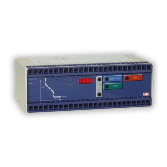
Page 10: Front Plate
The front plate of protection relays comprises the following operation and indication elements: Alphanumerical display (4 Digits) Push buttons for setting and other operations LEDs for measured value indication and setting Figure 3.4: Front plate XRI1-IR DOK-TD-XRI1-IR, Rev. C... -
Page 11: Display
<TRIP> three times Inquire password PSW? <TRIP><ENTER> Relay tripped TRIP <TRIP> or after fault trip- ping Secret password input XXXX <SELECT/RESET><+><-> <ENTER> System reset <SELECT/RESET> for about 3 s Table 3.1: Possible indication messages on the display DOK-TD-XRI1-IR, Rev. C... -
Page 12: Leds
The LEDs left from the display, L1, L2, L3, are partially bi-colored, the green indicating measuring, and the red fault indication. XRI1-IR with directional feature have a LED (green- and red arrow) for the directional display. At pickup/trip and parameter setting the green LED lights up to indicate the forward direction, the red LED indicates the reverse di- rection. -
Page 13: Working Principle
Digital circuits The essential part of the XRI1-IR relay is a powerful microcontroller. All of the operations, from the analog digital conversion to the relay trip decision, are carried out by the microcontroller digitally. The relay program is located in an EPROM (Electrically-Programmable-Read-Only-Memory). -
Page 14: Directional Feature
Manual XRI1-IR Directional feature A built-in directional element in XRI1-IR is available for application to doubly infeeded lines or to ring networks. The measuring principle for determining the direction is based on phase angle measurement and therefore also on coincidence time measurement between current and voltage. Since the necessary phase voltage for deter- mining the direction is frequently not available in the event of a fault, whichever line-to-line voltage follows the faulty phase by 90°... -
Page 15: Requirements On The Main Current Transformers
The low power consumption in the current circuit of XRI1-IR, namely <0.2 VA, has a positive effect on the selec- tion of current transformers. It implies that, if an electromechanical relay is replaced by XRI1-IR, a high accuracy limit factor is automatically obtained by using the same current transformer. -
Page 16: General Operations And Settings
An unintented or unauthorized change of the selected parameter is avoided by means of a password identification (see 5.4.2). The <TRIP>-push button is used to test the output relay circuits both for tripping and signalling. During normal operation it is also interlocked by means of the pass-word identification. DOK-TD-XRI1-IR, Rev. C... -
Page 17: Indication Of Measuring Values And Fault Data
<ENTER> has to be pressed. The graphic below shows again the difference between the different display modes. Figure 5.2: Switching over of the display in dependence of the operating mode DOK-TD-XRI1-IR, Rev. C... -
Page 18: Dip Switches
Dip switches Function Code jumper Operation mode position Password Normal position Password selection none Reset Output relays will be reset automatically Output relays will be reset manu- al/external/via software none Table 5.1: Summary of coding possibilities DOK-TD-XRI1-IR, Rev. C... -
Page 19: Reset
The XRI1-IR-relay is delivered with the preset password "++++", it can be programmed new with dip switch 1: Switch on dip switch 1. After power on and pressing any push button, the relay XRI1-IR inquires for a new password. The text "PSW?" appears on the display. The new password is entered by any combination of the push buttons <SELECT>... -
Page 20: Relay Setting Principle
5.5.2 Blocking the protection function The blocking function of the XRI1-IR-relays can be set according to requirement. When pressing push buttons <ENTER> and <TRIP> at the same time the blocking mode is entered. -
Page 21: Display Of Software Version And Test-Trip
≥ 70 V; U ≤ 60 V High-range threshold U Connection terminals Low-range blockage input terminal C1/C1L Low-range reset input terminal C2/C2L High-range blockage input terminal C1/C1H High-range reset input terminal C2/C2H DOK-TD-XRI1-IR, Rev. C... -
Page 22: Operations And Settings
When the time delay or the time multiplier is set out of range (Text "EXIT" appears on the display), the low set element of the overcurrent relay is blocked. The "WARN"-relay will not be blocked. For the XRI1-IR-version with directional feature, the different trip time delays or the time multipliers can be cho- sen for forward and backward faults. -
Page 23: Reset Setting For Inverse Time Tripping Characteristics In The Phase Current Path
Independent from the chosen tripping characteristic for I>, the high set element I>> has always a definite-time tripping characteristic. An indication value in seconds appears on the display. The setting procedure for forward or backward faults, described in chapter 6.1.3, is also valid for the tripping time of the high set element. DOK-TD-XRI1-IR, Rev. C... -
Page 24: Relay Characteristic Angle Rca
If after an activation the existing current drops again below the pickup value, e.g. I>, without a trip has been ini- tiated, LED I> signals that an activation has occurred by flashing fast. The LED keeps flashing until it is reset again (push button <RESET>). Flashing can be sup-pressed when the parameter is set to NOFL. DOK-TD-XRI1-IR, Rev. C... -
Page 25: Blocking The Protection Functions And Assignment Of The Output Relays
Assignment of the output relays: Unit XRI1-IR has five output relays. The fifth output relay is provided as permanent alarm relay for self supervi- sion is normally on. Output relays 1 - 4 are normally off and can be assigned as alarm or tripping relays to the current functions which can either be done by using the push buttons on the front plate or via serial interface RS485. -
Page 26: Setting Value Calculation
In case of a line-transformer combi- nation the setting values of the high set element can even be set for the fault inside the transformer. The time delay for high set element is always inde-pendent to the fault current. DOK-TD-XRI1-IR, Rev. C... -
Page 27: Inverse Time Overcurrent Element
All faults detected by the relay are indicated on the front plate optically. For this purpose, the four LEDs (L1, L2, L3, E) and the four function LEDs (I>, I>>, IE>, IE>> und →←) are equipped at XRI1-IR. If, for example an overcurrent occurs, first the LEDs of the corresponding phases will light up. -
Page 28: Fault Recorder
Expired tripping time of I> in % of tI> 2) I> C.B. switching time: Time between energizing of the trip output relay and switching of the C.B. (current <1% x I Expired tripping time: Time between pickup and release of the low set element. DOK-TD-XRI1-IR, Rev. C... -
Page 29: Reset
Manual XRI1-IR Woodward Reset Unit XRI1-IR has the following three possibilities to reset the display of the unit as well as the output relay at dip switch position 3=ON. Manual Reset Pressing the push button <SELECT/RESET> for some time (about 3 s) Electrical Reset ... -
Page 30: Relay Testing And Commissioning
<+><-> and <ENTER>. For detailed information about that, please refer to chapter 6. For a correct relay operation, be sure that the frequency set value (f=50/60) has been selected according to your system frequency (50 or 60 Hz). DOK-TD-XRI1-IR, Rev. C... -
Page 31: Secondary Injection Test
XRI1-IR is a three phase directional time overcurrent relay with relay connection angle of 90°. That is why the phase angle between input current and input voltage has to be set to -90° before the measuring procedure is started. - Page 32 49° phase angle lagging the current flowing from the marked end to the non-marked in the current input circuit. Of course, regardless of polarity, the current level must be above the pickup value. DOK-TD-XRI1-IR, Rev. C...
-
Page 33: Checking The Input Circuits And Measured Values
3% or 1% In. By using an RMS-metering instrument, a greater deviation may be observed if the test current contains harmonics. Because the XRI1-IR relay measures only the fundamental component of the input signals, the harmonics will be rejected by the internal DFFT-digital filter. Whereas the RMS-metering instrument measures the RMS-value of the input signals. -
Page 34: Checking The External Blocking And Reset Functions
Alternatively, the timer can be started when the aux. voltage and the test current are injected simultaneously. The timer stops when the corresponding output relay for circuit breaker failure protection trips. In this case the previously measured tripping delay (see section 6.4.5) has to be subtracted from the total trip- ping time measured. DOK-TD-XRI1-IR, Rev. C... -
Page 35: Primary Injection Test
In case of a XRI1-IR re-lay with directional feature, the active and reactive parts of the measured currents may be checked and the actual power factor may be calculated and compared it with the cosφ... -
Page 36: Technical Data
20% of the fifth harmonic; <0.07% per percent of the fifth harmonic Influences on delay times: no additional influences can be measured GL-approbation: 98 775 - 96 HH Bureau Veritas Approbation: 2650 6807 A00 H DOK-TD-XRI1-IR, Rev. C... -
Page 37: Setting Ranges And Steps
) − 1 �� �� Extremely Inverse (type C) > [ �� ] �� = ∙ �� �� �� − 1 �� �� Where: = tripping time tI> = time multiplier = fault current = Starting current DOK-TD-XRI1-IR, Rev. C... -
Page 38: Direction Unit For Phase Overcurrent Relay
Directional sensitivity for voltage input circuit: <0.025% U (phase-to-phase voltage) at I = 1 x I Connection angle: 90° Characteristic angle: 15°, 27°, 38°, 49°, 61°, 72°, 83° Effective angle: ±78° related to relay characteristic angle at U DOK-TD-XRI1-IR, Rev. C... -
Page 39: Inverse Time Characteristics
Inverse time characteristics 1000 I> 10.0 t[s] 0.05 5 6 7 8 910 Figure 8.1 Normal Inverse (type A) 1000 t[s] I> 10.0 0.05 0.05 0.01 5 6 7 8 910 Figure 8.2: Extremely Inverse (type C) DOK-TD-XRI1-IR, Rev. C... - Page 40 10.0 0.05 5 6 7 8 910 Figure 8.3: Very Inverse (type B) I> I> 0.02 0.02 t[s] > > 0.03 0.03 I>> I>> 40 40 >> >> 0.03 0.03 0.01 Figure 8.4: Definite time overcurrent relay DOK-TD-XRI1-IR, Rev. C...
-
Page 41: Output Relays
100 V, 110 V, 125 V, 220 V, 230 V ≤ 70 V ≥ 60 V Current consumption 1.5 mA DC at 360 V DC or 11.0 mA AC at 230 V DC Technical data subject to change without notice! DOK-TD-XRI1-IR, Rev. C... -
Page 42: System Data And Test Specifications
10 V/m Surge immunity test as per EN 61000-4-5:EN 61000-4-5: 2 kV Radio interference suppression test as per EN 55011: limit value class B Radio interference radiation test as per EN 55011: limit value class B DOK-TD-XRI1-IR, Rev. C... -
Page 43: Relay Case
Technical data subject to change without notice! Relay case Relay XRI1-IR is designed to be fastened onto a DIN-rail acc. to DIN EN 50022, the same as all units of the PROFESSIONAL LINE. The front plate of the relay is protected with a sealable transparent cover (IP40). -
Page 44: Order Form
Woodward Manual XRI1-IR 9. Order form Directional overcurrent relay XRI1 (with display and serial interface) Directional feature Rated current Rated voltage 100 V 400 V Communication protocol RS485 ProOpenData Modbus RTU DOK-TD-XRI1-IR, Rev. C... - Page 45 Manual XRI1-IR Woodward Setting list XRI1-IR Note ! All settings must be checked at site and should the occasion arise, adjusted to the object/item to be protected. Project: Woodward job.-no.: Function group: = Location: + Relay code: - Relay functions:...
- Page 46 Woodward Kempen GmbH Krefelder Weg 47 D – 47906 Kempen (Germany) Postfach 10 07 55 (P.O.Box) D – 47884 Kempen (Germany) Phone: +49 (0) 21 52 145 1 Internet www.woodward.com Sales Phone: +49 (0) 21 52 145 216 or 342 Telefax: +49 (0) 21 52 145 354 e-mail: salesEMEA_PGD@woodward.com...
Need help?
Do you have a question about the XRI1-IR and is the answer not in the manual?
Questions and answers