Table of Contents
Advertisement
Quick Links
Advertisement
Table of Contents

Subscribe to Our Youtube Channel
Related Manuals for Woodward MFR 3


Summary of Contents for Woodward MFR 3
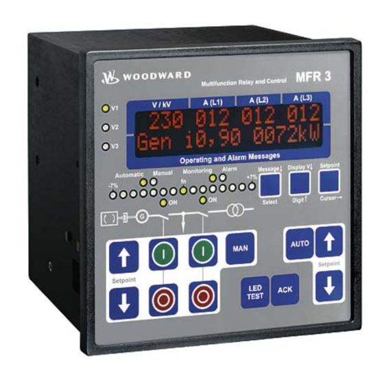
- Page 1 37107F MFR 3 Multi Function Relay Manual Software Version 3.4xxx Manual 37107F...
- Page 2 Provides other helpful information that does not fall under the warning or caution categories. Woodward reserves the right to update any portion of this publication at any time. Information provided by Woodward is believed to be correct and reliable. However, Woodward assumes no responsibility unless otherwise expressly undertaken.
-
Page 3: Table Of Contents
Operation Manual 37107F MFR 3 - Multi Function Relay Revision History Rev. Date Editor Changes NEW 04-05-05 Release 05-02-02 Minor corrections 05-07-12 Minor corrections, parameter numbers added, language revision 05-10-11 Minor corrections, changes of mains monitoring, relay and analog output manager, rotation field monitoring 08-08-20 Pulse outputs updated;... - Page 4 Operation Manual 37107F MFR 3 - Multi Function Relay 4. F ................... 31 HAPTER UNCTIONAL ESCRIPTION Function ..............................31 Operating Conditions ........................31 Direction of Power ..........................34 Power Factor Definition ......................... 34 Activation of the Circuit Breakers ......................36 ...
- Page 5 Operation Manual 37107F MFR 3 - Multi Function Relay Breaker ..............................88 Breaker Logic ..........................88 Synchronization ........................... 91 Synchronization Time Monitoring ....................92 Dead Bus Start ..........................93 Breaker Monitoring ........................94 ...
- Page 6 Operation Manual 37107F MFR 3 - Multi Function Relay D. A ................141 PPENDIX NALOG UTPUT ANAGER E. R ....................144 PPENDIX ELAY ANAGER F. I ..................146 PPENDIX NTERFACE ELEGRAM Transmission Telegram ........................146 Receiving Telegram ..........................151 ...
- Page 7 Operation Manual 37107F MFR 3 - Multi Function Relay Illustrations and Tables Illustrations Figure 3-1: Wiring diagram MFR 31 ............................16 Figure 3-2: Wiring diagram MFR 32 ............................17 Figure 3-3: Power supply ................................18 Figure 3-4: Measuring inputs - voltage - generator ........................18 ...
- Page 8 Operation Manual 37107F MFR 3 - Multi Function Relay Tables Table 3-1: Maximum CAN bus length ............................30 Table 4-1: Operating conditions - idle control and synchronization ..................31 Table 4-2: Operating conditions - idle control and synchronization - conditions ..............31 ...
-
Page 9: Chapter 1. General Information
The MFR 3 permits two circuit breakers to be synchronized and control of the mains power. The MFR 3 starts as a standard unit that may have additional functions added with each model. The model of the MFR 3 is designated as follows: MFR3 S45 -h0018 B/ PSV -ABDEF..Z... - Page 10 Operation Manual 37107F MFR 3 - Multi Function Relay Intended Use: The control unit must only be operated as described in this manual. The prerequisite for a proper and safe operation of the product is correct transportation, storage, and installation as well as careful operation and maintenance.
-
Page 11: Measuring
Operation Manual 37107F MFR 3 - Multi Function Relay Measuring ≡≡≡≡≡≡≡≡≡≡≡≡≡≡≡≡≡≡≡≡≡≡≡≡≡ Voltage The control unit performs three-phase true RMS measurement of two star or delta voltage systems (generator and mains). This unit can be delivered with the following measuring voltage ranges (rated values). The vol- tage measuring is specific to the part number ordered (please note chapter "Technical Data", page 138):... -
Page 12: Functional Range
Operation Manual 37107F MFR 3 - Multi Function Relay Functional Range ≡≡≡≡≡≡≡≡≡≡≡≡≡≡≡≡≡≡≡≡≡≡≡≡≡ The unit contains of the following features dependent upon the model: Function Option Package Common features Standard 1× ready for operation relay 4(2) *× control relays (N.O. contact) - Page 13 Operation Manual 37107F MFR 3 - Multi Function Relay Function Option Package Control/synchronization Synchronization of 2 circuit breakers with V and f control Standard Closing to a dead busbar (dead bus start) Standard Voltage control Standard Power factor control Standard...
-
Page 14: Chapter 2. Electrostatic Discharge Awareness
CAUTION To prevent damage to electronic components caused by improper handling, read and observe the pre- cautions in Woodward manual 82715, Guide for Handling and Protection of Electronic Controls, Printed Circuit Boards, and Modules. Page 14/165 © Woodward... -
Page 15: Chapter 3. Installation
Operation Manual 37107F MFR 3 - Multi Function Relay Chapter 3. Installation CAUTION A circuit breaker must be provided near to the device and in a position easily accessible to the opera- tor. This must also bear a sign identifying it as an isolating switch for the unit. -
Page 16: Wiring Diagram
X2/S2 (L) x2/s2 (l) s2 (l) Mains voltage L3 0 Vdc Mains voltage L2 12/24 Vdc Mains voltage L1 Subject to technical modifications. 2008-04-02 | MFR 3 Packages Wiring Diagram r3ww-1408-ap.SKF Figure 3-1: Wiring diagram MFR 31 Page 16/165 © Woodward... -
Page 17: Figure 3-2: Wiring Diagram Mfr 32
X2/S2 (L) x2/s2 (l) s2 (l) 0 Vdc Mains voltage L3 Mains voltage L2 12/24 Vdc Mains voltage L1 Subject to technical mocifications. 2005-10-10 | MFR 3 Packages Wiring Diagram r3ww-4105-ap.skf Figure 3-2: Wiring diagram MFR 32 © Woodward Page 17/165... -
Page 18: Power Supply
Operation Manual 37107F MFR 3 - Multi Function Relay Power Supply ≡≡≡≡≡≡≡≡≡≡≡≡≡≡≡≡≡≡≡≡≡≡≡≡≡ 9.5 to 32 Vdc D1 = P600M C1 = 47,000 uF / 40 V for 12 V DC systems 0 Vdc Power supply 9.5 to 32 Vdc 9.5 to 32 V DC (in normal operation) (min. -
Page 19: Figure 3-5: Measuring Inputs - Voltage - Busbar
Operation Manual 37107F MFR 3 - Multi Function Relay Busbar Synchronous Busbar voltage Figure 3-5: Measuring inputs - voltage - busbar Terminal Measuring Description 400 Vac Busbar voltage L1 2.5 mm² 100 Vac Busbar voltage L2 2.5 mm² Mains Mains voltage... -
Page 20: Current
Operation Manual 37107F MFR 3 - Multi Function Relay Current CAUTION Before disconnecting the secondary current transformer (CT) connections or the connections of the CT at the device, make sure that the CT is short-circuited. NOTE Generally current transformers should be grounded on one side. -
Page 21: Discrete Inputs
Operation Manual 37107F MFR 3 - Multi Function Relay Discrete Inputs ≡≡≡≡≡≡≡≡≡≡≡≡≡≡≡≡≡≡≡≡≡≡≡≡≡ CAUTION Please note that the maximum voltages which may be applied at the discrete inputs are defined as fol- lows. Voltages higher than those specified will destroy the hardware! Maximum input range: +/-18 to 250 Vac. -
Page 22: Alarm / Control Inputs
Operation Manual 37107F MFR 3 - Multi Function Relay Alarm / Control Inputs The discrete inputs may be either connected in a positive or a negative polarity: positive polarity The discrete input is connected with +/-18 to 250 Vac/dc. negative polarity The discrete input is connected with GND. -
Page 23: Analog Inputs
Operation Manual 37107F MFR 3 - Multi Function Relay Analog Inputs ≡≡≡≡≡≡≡≡≡≡≡≡≡≡≡≡≡≡≡≡≡≡≡≡≡ WARNING The analog inputs of the MFR are not isolated. When using an isolation monitor, we recommend to use two-pole, isolated transmitters. The analog inputs for active transmitters (0 to 20 mA, 0 to 10V) should only be operated with two-pole, isolated transmitters. -
Page 24: Relay Outputs
Operation Manual 37107F MFR 3 - Multi Function Relay Relay Outputs ≡≡≡≡≡≡≡≡≡≡≡≡≡≡≡≡≡≡≡≡≡≡≡≡≡ Control Outputs max. 250 V AC Command: close GCB Command: close MCB Command: open MCB Command: open GCB Figure 3-13: Relay outputs - control outputs - CB control... -
Page 25: Analog Outputs
Operation Manual 37107F MFR 3 - Multi Function Relay Analog Outputs ≡≡≡≡≡≡≡≡≡≡≡≡≡≡≡≡≡≡≡≡≡≡≡≡≡ Analog output Figure 3-15: Analog outputs Description Analog output [A1] - 0/4 to 20 mA 1.5 mm² Analog output [A2] - 0/4 to 20 mA 1.5 mm² Pulse Outputs ≡≡≡≡≡≡≡≡≡≡≡≡≡≡≡≡≡≡≡≡≡≡≡≡≡... -
Page 26: Controller Outputs
Operation Manual 37107F MFR 3 - Multi Function Relay Controller Outputs ≡≡≡≡≡≡≡≡≡≡≡≡≡≡≡≡≡≡≡≡≡≡≡≡≡ The controllers are configured in the standard version as three-position controllers (made up of a change-over contact and a normally open contact]. With option Q these contacts can be used as different types of outputs de- pending on the use of jumpers and the parameters selected. -
Page 27: Figure 3-19: Three-Position Controller - External Rc Wiring For Relay Manager
Operation Manual 37107F MFR 3 - Multi Function Relay Wiring of Controller Option Q - setting: THREESTEP (three-position controller) max. 250 Vac Relay output The relay has to be decoupled externally. Figure 3-19: Three-position controller - external RC wiring for relay manager... -
Page 28: Interface
Operation Manual 37107F MFR 3 - Multi Function Relay Interface ≡≡≡≡≡≡≡≡≡≡≡≡≡≡≡≡≡≡≡≡≡≡≡≡≡ Interface Wiring Y1 Y2 Y3 Y4 Y5 Figure 3-22: Interface - terminals Wiring Description Whether the terminals are designated X or Y depends on the configuration of the system. Please refer to the wiring diagram (A = X/Y, B = X/Y, etc.) -
Page 29: Can Bus Shielding
Operation Manual 37107F MFR 3 - Multi Function Relay CAN Bus Shielding Shield CAN-L Interface CAN-H CAN bus µ 0.01 400 Vac Figure 3-23: Interface - CAN bus shielding CAN Bus Loop NOTE Please note that the CAN bus must be terminated at both ends with an impedance which corresponds to the wave impedance of the cable (e.g. -
Page 30: Dpc - Direct Configuration Interface
Operation Manual 37107F MFR 3 - Multi Function Relay Maximum CAN Bus Length The maximum length of the communication bus wiring is dependent on the configured Baud rate. Refer to Table 3-1 for the maximum bus length (Source: CANopen; Holger Zeltwanger (Hrsg.); 2001 VDE VERLAG GMBH, Berlin und Offenbach;... -
Page 31: Chapter 4. Functional Description
Operation Manual 37107F MFR 3 - Multi Function Relay Chapter 4. Functional Description Function ≡≡≡≡≡≡≡≡≡≡≡≡≡≡≡≡≡≡≡≡≡≡≡≡≡ Operating Conditions Idle Control and Synchronization Idle control: Generator voltage and frequency are adjusted to the configured set point values by raising and lo- wering the controller outputs for voltage and speed/frequency as required. -
Page 32: Table 4-3: Operating Conditions - Dead Bus Start
Operation Manual 37107F MFR 3 - Multi Function Relay Dead Bus Start Dead bus start: Output of a connect command for the circuit breaker without synchronization. Input signals [terminal] Function Dead bus start GCB Dead bus start MCB 0: "OFF" / 1: "ON" / x: signal has no significance (0 or 1) Table 4-3: Operating conditions - dead bus start The busbar must be de-energized. -
Page 33: Table 4-6: Operating Conditions - Mains Parallel Operation
Operation Manual 37107F MFR 3 - Multi Function Relay Mains Parallel Operation Mains parallel operation: The controller outputs raise and lower speed/frequency and voltage to adjust real power and power factor of the generator to the configured set point values. -
Page 34: Direction Of Power
Operation Manual 37107F MFR 3 - Multi Function Relay Direction of Power ≡≡≡≡≡≡≡≡≡≡≡≡≡≡≡≡≡≡≡≡≡≡≡≡≡ If the unit's current transformers are wired according to the pin diagram shown, the following values are dis- played: The generator supplies real power. Positive generator real power The generator is overexcited and supplies inductive reactive power. - Page 35 Operation Manual 37107F MFR 3 - Multi Function Relay Different power factor displays at the unit: i0.91 (inductive) c0.93 (capacitive) lg.91 (lagging) ld.93 (leading) Reactive power display at the unit: 70 kvar (positive) -60 kvar (negative) Output at the interface:...
-
Page 36: Activation Of The Circuit Breakers
Operation Manual 37107F MFR 3 - Multi Function Relay Activation of the Circuit Breakers ≡≡≡≡≡≡≡≡≡≡≡≡≡≡≡≡≡≡≡≡≡≡≡≡≡ Operating Sequence for the MCB Figure 4-2 represents the switch behavior for the following settings: MCB open via "Enable MCB": ON Additional information can be obtained from the descriptions of the configuration screens. -
Page 37: Operating Sequence For The Gcb
Operation Manual 37107F MFR 3 - Multi Function Relay Operating Sequence for the GCB Figure 4-3 represents the switch behavior for the following settings: Shutdown: ON Relay "Command: open GCB", logic: A (operating current; NO) GCB continuous pulse: OFF Additional information can be obtained from the descriptions of the configuration screens. -
Page 38: Analog Controller Outputs
Operation Manual 37107F MFR 3 - Multi Function Relay Analog Controller Outputs ≡≡≡≡≡≡≡≡≡≡≡≡≡≡≡≡≡≡≡≡≡≡≡≡≡ The control unit may be equipped with an analog controller output in addition to a three-position controller out- put. Additional configuration screens appear in configuration mode. The analog PID controller forms a closed- loop control loop along with the controlled system (usually a first-order lag element). -
Page 39: Controller Setting
Operation Manual 37107F MFR 3 - Multi Function Relay : Highest transient deviation value during the transition from one steady-state condition to a new Overshoot x ≤ steady-state condition following modification of the disturbance variable or reference input variable (x m Optimal 10 %). -
Page 40: Figure 4-6: Step Response - Controller Setting
Operation Manual 37107F MFR 3 - Multi Function Relay Controller operated as a P-only controller = ∞ [Parameter setting: T (where T = 0], T = 0). Increase gain K (P gain) until the control loop oscillates continuously at K... -
Page 41: Load And/Or Var Sharing
Operation Manual 37107F MFR 3 - Multi Function Relay Load and/or Var Sharing ≡≡≡≡≡≡≡≡≡≡≡≡≡≡≡≡≡≡≡≡≡≡≡≡≡ The control ensures load and/or var sharing proportional to the rated power of the generators under every operat- ing condition (mains parallel operation, isolated operation in parallel with other gensets, or reverse synchroniza- tion of the busbar to the mains). -
Page 42: Figure 4-7: Load/Var Sharing - Schematic
Operation Manual 37107F MFR 3 - Multi Function Relay Pre-requisites: It is imperative that the rated system frequencies (page 64) and the circuit breaker logic (page 88) are set identically for all units participating in load/var sharing. Description of the interface for load/var sharing: Load/var sharing is based on a multi-master-capable bus be- tween the controls. -
Page 43: Language Manager
Operation Manual 37107F MFR 3 - Multi Function Relay Language Manager ≡≡≡≡≡≡≡≡≡≡≡≡≡≡≡≡≡≡≡≡≡≡≡≡≡ NOTE Please also note the parameters to this option in chapter Language Manager at page 56. In order to load a different language into the unit, please proceed as follows: Establish a connection between your PC and the unit via the direct configuration cable (DPC) or via a Ga- teway GW 4. -
Page 44: Alarms
Operation Manual 37107F MFR 3 - Multi Function Relay Alarms ≡≡≡≡≡≡≡≡≡≡≡≡≡≡≡≡≡≡≡≡≡≡≡≡≡ Alarm Class The monitoring functions are divided into four alarm classes: F0 - Warning alarm - This alarm does not lead to an interruption of the operation. An alarm message is dis- played without a centralized alarm. -
Page 45: Alarm Acknowledgement
Operation Manual 37107F MFR 3 - Multi Function Relay Alarm Acknowledgement By pressing the "ACK" push button, the output of the centralized alarm and the alarm messages on the LC dis- play are acknowledged according to the following logic: Horn: After 2 minutes the horn is reset regardless of the acknowledgement of an alarm. -
Page 46: Chapter 5. Display And Push-Buttons
Operation Manual 37107F MFR 3 - Multi Function Relay Chapter 5. Display and Push-Buttons The pressure-sensitive membrane of the front panel consists of a plastic coating. All keys have been designed as touch-sensitive membrane switch elements. The display is an LC display, comprised of 2 lines with 16 characters each, which are indirectly illuminated in red. -
Page 47: Brief Description Of Led And Push-Buttons
Operation Manual 37107F MFR 3 - Multi Function Relay Brief Description of LED and Push-Buttons ≡≡≡≡≡≡≡≡≡≡≡≡≡≡≡≡≡≡≡≡≡≡≡≡≡ LEDs No. Description Function Voltage L1 Voltage L2 Voltage L3 -7%..fn..+7% Synchroscope Automatic Operating mode AUTOMATIC selected Manual Operating mode MANUAL selected Monitoring Monitoring is activated... -
Page 48: Leds
Operation Manual 37107F MFR 3 - Multi Function Relay LEDs ≡≡≡≡≡≡≡≡≡≡≡≡≡≡≡≡≡≡≡≡≡≡≡≡≡ V1 - V2 - V3 Voltage control Color: Green The LED's "V1", "V2" and "V3" show which voltage (V or V ) is currently being displayed. This applies both to the ge- nerator and the mains voltage display. -
Page 49: Push-Buttons
Operation Manual 37107F MFR 3 - Multi Function Relay Monitoring Monitoring Color: Green If the "Monitoring" LED is illuminated, monitoring is enabled. The delayed programmed alarm inputs are monitored in addition to the permanently mo- nitored alarm inputs. Generator underspeed, underfrequency, undervoltage and reverse power are also monitored. - Page 50 Operation Manual 37107F MFR 3 - Multi Function Relay Display V↓ / Digit↑ Display V↓ / Digit↑ Color: Blue Normal operation: Display V↓ - By pressing this push-button, the genera- tor and mains voltage display is moved forwards. Note: If this push-button is pressed for at least 5 seconds, the counter that is currently been displayed is (re)set.
-
Page 51: Control Of The Power Circuit Breakers
Operation Manual 37107F MFR 3 - Multi Function Relay Control of the Power Circuit Breakers GCB ON / GCB OFF Close GCB / open GCB Color: Green/Red Note: This function is only enabled if the MANUAL operation mode has been enabled. -
Page 52: Lc Display
Operation Manual 37107F MFR 3 - Multi Function Relay LED Test Check LED's Color: Blue All control unit LED’s are illuminated by pressing this button to check for proper operation. Acknowledgment Color: Blue Alarm messages are acknowledged pressing the "ACK" push button. The alarm messages on the LC display are cleared and the "Alarm"... -
Page 53: Automatic Mode (Second Display Line: Measuring Values)
Operation Manual 37107F MFR 3 - Multi Function Relay Automatic Mode (Second Display Line: Measuring Values) NOTE The bottom line can be scrolled using the "Message↓" push button. It is also possible, to scroll through any alarms that may be present using the "Message↓" push button. -
Page 54: Automatic Mode (Second Display Line: Alarm Display)
Operation Manual 37107F MFR 3 - Multi Function Relay Automatic Mode (Second Display Line: Alarm Display) NOTE It is possible to scroll through any alarms that may be present using the "Message↓" push-button. Display in automatic mode, second line: alarms... -
Page 55: Chapter 6. Configuration
Operation Manual 37107F MFR 3 - Multi Function Relay Chapter 6. Configuration Configuration can be performed via the front panel push buttons and LC display or using a PC and the LeoPC1 program with the serial interface. Additionally it is possible to configure the unit via CAN bus. The following baud rates apply to each method: •... -
Page 56: Introduction
Operation Manual 37107F MFR 3 - Multi Function Relay Introduction ≡≡≡≡≡≡≡≡≡≡≡≡≡≡≡≡≡≡≡≡≡≡≡≡≡ The configuration screens have an AUTOROLL function when you are in configuration mode (simultaneously pressing "Digit↑" and "Cursor→"). If the "Select" button is pressed and held, the scroll function will be activated and the user will be able to rapidly advance through the parameter screens. -
Page 57: Version Number
Operation Manual 37107F MFR 3 - Multi Function Relay NOTE Please also note chapter "Direct Configuration" on page 63. Parameter 5 Direct configuration YES/NO Direct para. YES ....The language will be uploaded via the DPC and the DPC connection is disabled. - Page 58 Operation Manual 37107F MFR 3 - Multi Function Relay Service Display for Versions with Voltage Transformers (100 V) Double voltage/frequency display B 00,0kV 00,00Hz G 00,0kV 00,00Hz The generator and busbar voltage and frequency are displayed. The phase angle be- tween the generator and busbar is displayed by the synchroscope (LED strip): B ....
-
Page 59: Password Protection
Operation Manual 37107F MFR 3 - Multi Function Relay Password Protection ≡≡≡≡≡≡≡≡≡≡≡≡≡≡≡≡≡≡≡≡≡≡≡≡≡ The unit is equipped with a three-level code and configuration hierarchy. This permits multiple levels of access to configuration screens for different users. A distinction is made between: Code level 0 (CS0) - User: Third Party Only monitoring of measured values is permitted. -
Page 60: Event Recorder
Operation Manual 37107F MFR 3 - Multi Function Relay Event Recorder ≡≡≡≡≡≡≡≡≡≡≡≡≡≡≡≡≡≡≡≡≡≡≡≡≡ NOTE The viewing and acknowledgment of alarms depends on access authorization: Viewing of alarms Access authorization CS 0, CS 1 and CS Acknowledgment of alarms Access authorization CS CS = code level (see chapter "Alarm Class"... -
Page 61: Table 6-1: Event Recorder - Messages - Part 1
Operation Manual 37107F MFR 3 - Multi Function Relay Type of alarm xxxxxxxxxxxxxxxx German English Internal alarm Generator overfrequency, level 1 Gen.Überfreq. 1 Gen.overfreq. 1 Generator overfrequency, level 2 Gen.Überfreq. 2 Gen.overfreq. 2 Generator underfrequency, level 1 Gen.Unterfreq. 1 Gen.underfreq. 1 Generator underfrequency, level 2 Gen.Unterfreq. -
Page 62: Analog Inputs
Operation Manual 37107F MFR 3 - Multi Function Relay Type of alarm xxxxxxxxxxxxxxxx German English Others Change into operating mode MANUAL BAW Hand Manual mode Change into operating mode AUTOMATIC BAW Automatik Automatic mode Push-button "MCB OFF" depressed (in operating mode MANUAL) -
Page 63: Direct Configuration
Operation Manual 37107F MFR 3 - Multi Function Relay Direct Configuration ≡≡≡≡≡≡≡≡≡≡≡≡≡≡≡≡≡≡≡≡≡≡≡≡≡ NOTE To carry out direct configuration, you require a direct configuration cable (order code "DPC"), the LeoPC1 program (supplied with the cable) and the corresponding configuration files. After the program has been installed, consult the online help utility for a description of the PC program and its setup. -
Page 64: Basic Settings
Operation Manual 37107F MFR 3 - Multi Function Relay Basic Settings ≡≡≡≡≡≡≡≡≡≡≡≡≡≡≡≡≡≡≡≡≡≡≡≡≡ CAUTION Failure to ensure correct configuration of parameters may lead to incorrect measurements and the con- trol failing to respond properly! Parameter 11 Configure base settings YES/NO Configure... - Page 65 Operation Manual 37107F MFR 3 - Multi Function Relay Voltage Transformer, PTs CAUTION If the following parameter values are modified, the values of the following parameters must be verified: • generator voltage set point (at page 66) • voltage controller dead band (at page 77) •...
- Page 66 Operation Manual 37107F MFR 3 - Multi Function Relay CAUTION If the following parameter values are modified, the values of the following parameters must be verified: • mains overvoltage tripping value (at page 112) • mains undervoltage tripping value (at page 112)
- Page 67 Operation Manual 37107F MFR 3 - Multi Function Relay Parameter 23 Voltage measuring system threephase/singlephase Voltage system Three-phase network The electrical system (generator, busbar, and mains) is a ---------------- delta system consisting of only the three external conductors (without This screen only affects the dis- a neutral conductor).
- Page 68 Operation Manual 37107F MFR 3 - Multi Function Relay Generator Current, CT Parameter 25 CT ratio, generator [5] 10 to 7,000/5 Current transf. The current transformer ratio is necessary in order to display the actual values and generator 0000/x control the power. When sizing a CT for the system, the minimum current flow for the CT should not be lower than 60% of the transformer's rated current at rated cur- rent.
- Page 69 Operation Manual 37107F MFR 3 - Multi Function Relay NOTE The following parameter is only available for units with a software version of 3.4006 or higher. Units with a lower software version use the internal value “3”. Parameter 26 Power display format...
- Page 70 Operation Manual 37107F MFR 3 - Multi Function Relay Example: S = UGNPRIM * IGNPRIM * √3 = 10 kV * 200 A* √3 = 3,46 MVA If this parameter is configured to "3" (default), the power format is 00.0 MW, if it is configured to "4", it is 0000 kW.
- Page 71 Operation Manual 37107F MFR 3 - Multi Function Relay Mains Current, CT / Mains Power Mains current measuring via mains current transformer/CT Parameter 30 CT ratio, mains 5 to 7,000/x A Current transf. The current transformer ratio is necessary in order to display the actual values and...
-
Page 72: Change Passwords
Operation Manual 37107F MFR 3 - Multi Function Relay Change Passwords NOTE Once the code level is entered, access to the configuration menus will be allowed for two hours after the last function is performed or until another password is entered into the control. If a user needs to exit a code level then code level CS0 should be entered. -
Page 73: Controller
Operation Manual 37107F MFR 3 - Multi Function Relay Controller ≡≡≡≡≡≡≡≡≡≡≡≡≡≡≡≡≡≡≡≡≡≡≡≡≡ CAUTION Entering incorrect values can lead to the control unit failing to function properly and destroy the gene- rator! Parameter 34 Configure controllers YES/NO Configure Various groups of parameters are grouped together in blocks to aid in the rapid na- Controller vigation through the large number of configuration screens. -
Page 74: Frequency Controller
Operation Manual 37107F MFR 3 - Multi Function Relay Parameter 36 P controller: setpoint value 2 C/I/E 0 to 16,000 kW Power controller Setpoint 2 is enabled when the discrete input "Setpoint 1↔2" is energized (voltage Pset2 I0000kW applied to terminal 5) and the external setpoint value (via 0/4 to 20 mA analog in- put or interface) has not been selected. - Page 75 Operation Manual 37107F MFR 3 - Multi Function Relay NOTE The following settings in the n/f controller area affect the P controller. Parameter 42 f controller: type THREESTEP / ANALOG / PWM F/P contr.type THREESTEP The signal to control the speed/frequency/real power is output via ---------------- the relay manager to any configured relay.
- Page 76 Operation Manual 37107F MFR 3 - Multi Function Relay Analog Controller Output (Setting ANALOG/PWM) Parameter 46 f controller: output range see below F/P contr.output If Parameter 42 "F/P contr. type" has been configured as "ANALOG", the type of ---------------- analog output must be selected in this screen. The use of a jumper between termin- als 8/9 determines if the output is a voltage or current output.
-
Page 77: Voltage Controller
Operation Manual 37107F MFR 3 - Multi Function Relay Parameter 49 f controller: reset time 0.0 to 60.0 s Freq.controller The reset time T represents the I-component of the PID controller. The reset time reset Tn 00.0s corrects for any offset (between set point and process variable) automatically over time by shifting the proportioning band. - Page 78 Operation Manual 37107F MFR 3 - Multi Function Relay Three-Position Controller (Setting THREESTEP) Parameter 54 V controller: dead band [1] 0.1 to 15.0 V; [4] 0.5 to 60.0 V Volt.controller Isolated operation The generator voltage set point is controlled in such a manner, dead band 00.0V...
- Page 79 Operation Manual 37107F MFR 3 - Multi Function Relay Analog Controller (Setting ANALOG) Parameter 57 V controller: range see below V/Q contr.output If Parameter 53 "V/Q contr. type" has been configured as "ANALOG", the type of ---------------- analog output must be selected in this screen. The use of a jumper between termin- als 11/12 determines if the output is a voltage or current output.
-
Page 80: Power Factor Controller
Operation Manual 37107F MFR 3 - Multi Function Relay Power Factor Controller Parameter 61 Power factor controller ON/OFF Pow.fact.contr. ON ....The power factor is controlled independent of the load in mains pa- rallel operations. If the measured secondary currents are lower than 5% of the rated current, the power factor cannot be accurately meas- ured. - Page 81 Operation Manual 37107F MFR 3 - Multi Function Relay Three-Position Controller (Setting THREESTEP) Parameter 67 Power factor controller: dead band 0.5 to 25.0 % Pow.fact.contr. The unit automatically calculates the amount of re-active power, which is required dead band 00.0% to maintain the configured power factor.
-
Page 82: Real Power Controller
Operation Manual 37107F MFR 3 - Multi Function Relay Real Power Controller Parameter 72 P controller ON/OFF Power controller ON ....In a mains parallel operation, the real power is automatically con- trolled at the configured set point (see page 73) when the real power controller is enabled. - Page 83 Operation Manual 37107F MFR 3 - Multi Function Relay External Set Point Value Parameter 76 P set point: external set point value ON/OFF Power setpoint ON ....The real power set point 2 value may be specified via an external external signal.
- Page 84 Operation Manual 37107F MFR 3 - Multi Function Relay Three-Position Controller (Setting THREESTEP) Parameter 80 P controller: dead band 0.1 to 25.0 % Power controller In mains parallel operation, the real power is controlled in such a manner, that in its dead band 00.0%...
- Page 85 Operation Manual 37107F MFR 3 - Multi Function Relay Analog Ccontroller (Setting ANALOG) Parameter 83 P controller: P gain 1 to 240 Power controller The proportional-action coefficient K indicates the closed-loop control system gain Kpr gain. By increasing the gain, the response is increased to permit larger corrections to the variable to be controlled.
-
Page 86: Load/Var Sharing
Operation Manual 37107F MFR 3 - Multi Function Relay Load/var Sharing Parameter 88 Load sharing ON/OFF Active power ON ....Real power is shared between all generators operating in parallel. load share The power output by each generator is dependent upon the indivi- dually configured values. -
Page 87: Interface
Operation Manual 37107F MFR 3 - Multi Function Relay Interface CAN Bus (Terminal X1 to X5) Parameter 92 CAN bus: control via interface COM X1-X5 ON/OFF Control via ON ....Control via the serial interface is enabled if the direct configuration COM X1X5 parameter is configured to "OFF"... -
Page 88: Breaker
Operation Manual 37107F MFR 3 - Multi Function Relay Breaker ≡≡≡≡≡≡≡≡≡≡≡≡≡≡≡≡≡≡≡≡≡≡≡≡≡ Parameter 93 Configure breakers YES/NO Configure Various groups of parameters are grouped together in blocks to aid in the rapid na- Breaker vigation through the large number of configuration screens. Selecting "YES" or "NO"... - Page 89 The MCB and the GCB can be manually opened and closed without All breaker control must be carried out via a master controller (e.g. a synchronization. The circuit breakers are opened for decoupling PLC). The MFR 3 issues the breaker open commands under fault from the mains. conditions.
- Page 90 Operation Manual 37107F MFR 3 - Multi Function Relay Parameter Parameter 95 Add-on/add-off ramp 0 to 999 s Add-off ramp This time can be used to influence two functions: max.time 000s Add-off: The maximum amount of time the generator has to shed load below 3% of the generator load rating (Parameter 28) is configured here.
-
Page 91: Synchronization
Operation Manual 37107F MFR 3 - Multi Function Relay Synchronization Parameter 99 Synch.: max. permissible differential frequency (pos. slip) 0.02 to 0.49 Hz Synchronize This is the upper frequency differential limit for synchronization. The prerequisite df max 0.00Hz for a breaker closure command is that the positive frequency differential be lower than the configured value. -
Page 92: Synchronization Time Monitoring
Operation Manual 37107F MFR 3 - Multi Function Relay Synchronization Time Monitoring Parameter 106 Synchronization time monitoring ON/OFF Sync.time contr. ON ....Synchronization time monitoring is performed. The subsequent screens of this function are displayed. OFF ....Synchronization time monitoring is not performed. Synchronization is attempted until it is accomplished. -
Page 93: Dead Bus Start
Operation Manual 37107F MFR 3 - Multi Function Relay Dead Bus Start If the busbar is in a voltage-free state, the direct connection (dead bus start) of the GCB or MCB may be carried out. If both connect commands are issued simultaneously, priority is given to the MCB if the input "Enable MCB"... -
Page 94: Breaker Monitoring
Operation Manual 37107F MFR 3 - Multi Function Relay Breaker Monitoring Parameter 113 Breaker monitoring GCB ON/OFF Supervision GCB ON ....Monitoring of the GCB is performed (except in the "EXTERNAL" CB logic). If the circuit breaker cannot be closed by the fifth attempt, the relay manager function 89 relay is energized and a class F1 alarm and message are issued. -
Page 95: Protection
Operation Manual 37107F MFR 3 - Multi Function Relay Protection ≡≡≡≡≡≡≡≡≡≡≡≡≡≡≡≡≡≡≡≡≡≡≡≡≡ Parameter 117 Configure monitoring YES/NO Configure Various groups of parameters are grouped together in blocks to aid in the rapid na- Monitoring vigation through the large number of configuration screens. Selecting "YES" or "NO"... -
Page 96: Reverse/Reduced Power Monitoring
Operation Manual 37107F MFR 3 - Multi Function Relay Reverse/Reduced Power Monitoring NOTE All percentage indications of the power are in relation to the generator rated power (Parameter 28). Function: "Real power not within the permissible range" The real power measured in a single phase or in three phases is below the configured limit value for the mini- mum load or below the configured value for reverse power. -
Page 97: Generator Overload Monitoring
Operation Manual 37107F MFR 3 - Multi Function Relay Generator Overload Monitoring NOTE All percentage indications of the power are in relation to the generator rated power (Parameter 28). Function: "Positive real power not within the permissible range" The real power of the generator is outside the configured overload limit values, and an alarm is issued. -
Page 98: Generator Re-Active Power Monitoring
Operation Manual 37107F MFR 3 - Multi Function Relay Generator Re-active Power Monitoring NOTE All percentage indications of the power are in relation to the generator rated power (Parameter 28). Function: "Re-active power not within the permissible range" The re-active power of the generator is outside the configured re-active power limits, and an alarm is issued. -
Page 99: Time-Overcurrent Monitoring (Toc)
Operation Manual 37107F MFR 3 - Multi Function Relay Time-Overcurrent Monitoring (TOC) NOTE All percentage indications of the current are in relation to the generator rated current (Parameter 29). Function: The user may configure two steps for time-overcurrent monitoring. The threshold values and delays can be configured so that the individual set points are independent of each other. -
Page 100: Inverse Time-Overcurrent Monitoring
Operation Manual 37107F MFR 3 - Multi Function Relay Parameter 138 Time-overcurrent: limit 2 0 to 300 % Gen.overcurr. 2 The value configured in this screen is a percentage of the configured generator resp.value 000% rated current. If this level is reached or exceeded for the configured delay time, the unit issues an alarm and opens the GCB. -
Page 101: Figure 6-2: Inverse Time-Overcurrent - Characteristic "Normal Inverse
Operation Manual 37107F MFR 3 - Multi Function Relay Configuration Screens Parameter 140 Inverse time-overcurrent monitoring ON/OFF Inv.time ov.cur. ON ....Inverse time-overcurrent monitoring is enabled. The subsequent Monitor. screens of this function are displayed. OFF ....Inverse time-overcurrent monitoring is disabled. The subsequent screens of this function are not displayed. -
Page 102: Figure 6-3: Inverse Time-Overcurrent - Characteristic "High Inverse
Operation Manual 37107F MFR 3 - Multi Function Relay Highly Inverse Ip = In; I start = 1.1 x In t[s] 1000 tp = 1.6 s tp = 1.0 s tp = 0.5 s tp = 0.2 s tp = 0.1 s tp = 0.05 s... -
Page 103: Inverse Time-Overcurrent Monitoring With Voltage Restraint
Operation Manual 37107F MFR 3 - Multi Function Relay Inverse Time-Overcurrent Monitoring with Voltage Restraint NOTE This monitoring function is an additional functionality for the inverse time overcurrent monitoring func- tion. If the inverse time overcurrent monitoring is disabled (Parameter 140), time-overcurrent monitor- ing with voltage restraint is disabled too. - Page 104 Operation Manual 37107F MFR 3 - Multi Function Relay Example: Initial conditions: Rated voltage V = 100 V Configured value I = 2.0*5 A = 10 A (rated current I = 5 A) Case 1 (monitored voltage V > 90% V As long as the monitored voltage exceeds 90% of the rated voltage, the configured value will not be adjusted.
-
Page 105: Earth Fault Monitoring
Operation Manual 37107F MFR 3 - Multi Function Relay Earth Fault Monitoring Calculation of the ground current: The measuring of the ground current is based on the calculation of the vectoral sum of the three phase currents. To ensure that the ground fault protection operates properly, the configured ground currents should be a mini- mum of 10% of the current transformer’s rating. -
Page 106: Generator Load Imbalance Monitoring
Operation Manual 37107F MFR 3 - Multi Function Relay Generator Load Imbalance Monitoring NOTE All percentage indications of the current are in relation to the generator rated current (Parameter 29). Function: "Generator load imbalance not within the permissible range" The threshold value, expressed as a percentage,specifies the permissible deviation of the current in a conductor from the calculated mean value of all three-conductor currents. -
Page 107: Generator Overfrequency Monitoring
Operation Manual 37107F MFR 3 - Multi Function Relay Generator Overfrequency Monitoring The monitoring of the frequency is carried out at two levels. The measurement of the frequency encompasses all three phases if all voltages are greater than 15 % of the rated value (100 Vac or 400 Vac). This enables a very rapid and precise frequency measurement. -
Page 108: Generator Underfrequency Monitoring
Operation Manual 37107F MFR 3 - Multi Function Relay Generator Underfrequency Monitoring The monitoring of the frequency is carried out at two levels. The measurement of the frequency encompasses all three phases if all voltages are greater than 15 % of the rated value (100 Vac or 400 Vac). This enables a very rapid and precise frequency measurement. -
Page 109: Generator Overvoltage Monitoring
Operation Manual 37107F MFR 3 - Multi Function Relay Generator Overvoltage Monitoring The line-to-line voltage is monitored to detect overvoltage conditions. Function: "Generator voltage not within the permissible range" At least one phase of the generator voltage is outside of the limit values configured for overvoltage. The enabling of generator overvoltage monitoring is delayed via "Delayed monitoring"... -
Page 110: Generator Undervoltage Monitoring
Operation Manual 37107F MFR 3 - Multi Function Relay Generator Undervoltage Monitoring The line-to-line voltage is monitored to detect undervoltage conditions. Function: "Generator voltage not within the permissible range" At least one phase of the generator voltage is outside of the limit values configured for undervoltage. The enabl- ing of generator undervoltage monitoring is delayed via "Delayed monitoring"... -
Page 111: Mains Frequency Monitoring
Operation Manual 37107F MFR 3 - Multi Function Relay Mains Frequency Monitoring NOTE The "Blocking of mains protection" input (terminal 61) disables mains monitoring and decoupling. Monitoring of the mains frequency is absolutely vital if a generator is to be operated in parallel with a public util- ity. -
Page 112: Mains Voltage Monitoring
Operation Manual 37107F MFR 3 - Multi Function Relay Mains Voltage Monitoring NOTE The "Blocking of mains protection" input (terminal 61) disables mains monitoring and decoupling. Monitoring the mains voltage is absolutely vital if a generator is to be operated in parallel with a public utility. In the event of mains failure (e. - Page 113 Operation Manual 37107F MFR 3 - Multi Function Relay Parameter 183 Mains undervoltage: limit [1] 20 to 150 V; [4] 20 to 520 V Mains undervolt. The phase-phase voltage value for mains undervoltage limit is configured in this U Ph.-Ph.<...
-
Page 114: Mains Dϕ/Dt Phase/Vector Shift Monitoring
Operation Manual 37107F MFR 3 - Multi Function Relay Mains dϕ/dt Phase/Vector Shift Monitoring NOTE The "Blocking of mains protection" input (terminal 61) disables mains monitoring and decoupling. A dϕ/dt phase/vector jump is a sudden change in the voltage vector angle, and may be caused by a major genera- tor load change. - Page 115 Operation Manual 37107F MFR 3 - Multi Function Relay NOTE If monitoring is configured to "three phase only", only the second screen will be displayed; if moni- toring is configured to "one/three-phase", both screens are displayed. Parameter 188 dϕ/dt phase/vector shift: limit single-phase 3 to 30 °...
-
Page 116: Mains Df/Dt Rate Of Change Of Frequency Monitoring (Rocof)
Operation Manual 37107F MFR 3 - Multi Function Relay Mains df/dt Rate Of Change Of Frequency Monitoring (ROCOF) NOTE The "Blocking of mains protection" input (terminal 61) disables mains monitoring and decoupling. Function: "Frequency change per time unit not within the permissible range"... -
Page 117: Battery Voltage Monitoring
Operation Manual 37107F MFR 3 - Multi Function Relay Battery Voltage Monitoring Parameter 194 Battery voltage: limit 9.5 to 30.0 V Batt.undervolt. The battery undervoltage threshold value is configured in this screen. If the moni- U < 00.0V tored voltage reaches or is falls below this level for the configured delay time, the unit issues an alarm. -
Page 118: Discrete Inputs
Operation Manual 37107F MFR 3 - Multi Function Relay Discrete Inputs ≡≡≡≡≡≡≡≡≡≡≡≡≡≡≡≡≡≡≡≡≡≡≡≡≡ Parameter 196 Configure discrete inputs YES/NO Configure Various groups of parameters are grouped together in blocks to aid in the rapid na- Dig.input vigation through the large number of configuration screens. Selecting "YES" or "NO"... -
Page 119: Breaker Logic Via Discrete Input [D03]
Operation Manual 37107F MFR 3 - Multi Function Relay Breaker Logic via Discrete Input [D03] Parameter 199 Breaker logic via discrete input [D03] ON/OFF Breaker logic ON ....This discrete input is used as a control input: via term.64 • Discrete input [D03] (terminal 64) is... -
Page 120: Discrete Inputs: Text
Operation Manual 37107F MFR 3 - Multi Function Relay Parameter 202 Discrete input: delay 0 to 9 Dig.input 1234 A delay can be assigned to each alarm input. The delay is entered in the form of de- delay 0000 lay stages. The individual stages are listed below. The input must be present, with- out interruption, before the configured time period before the alarm is issued. -
Page 121: Analog Inputs
Operation Manual 37107F MFR 3 - Multi Function Relay Analog Inputs ≡≡≡≡≡≡≡≡≡≡≡≡≡≡≡≡≡≡≡≡≡≡≡≡≡ Parameter 206 Configure analog inputs YES/NO Configure Various groups of parameters are grouped together in blocks to aid in the rapid na- Analg.inp. vigation through the large number of configuration screens. Selecting "YES" or "NO"... - Page 122 Operation Manual 37107F MFR 3 - Multi Function Relay Pt100 Input ([T4] to [T7]) The Pt100 temperature input is designed for temperatures up to 240 °C. A name may be assigned to each Pt100 input. Each input is displayed with its name, and can be monitored in two stages. The first stage initiates a class 1 alarm, and the second stage initiates a class 3 alarm.
- Page 123 Operation Manual 37107F MFR 3 - Multi Function Relay Analog Input 0/4 to 20 mA ([T2]-[T3]) 0/4 to 20 mA values can be read here. A name and a unit of measurement may be assigned to the input. The ana- log input is displayed with its name, and can be monitored in two stages.
- Page 124 Operation Manual 37107F MFR 3 - Multi Function Relay Parameter 220 Analog input, 0/4 to 20 mA: delay (limit 1 + 2) 0 to 600 s Delay The analog input monitoring threshold limit must be exceeded, without interrup- Limit 1/2...
-
Page 125: Outputs
Operation Manual 37107F MFR 3 - Multi Function Relay Outputs ≡≡≡≡≡≡≡≡≡≡≡≡≡≡≡≡≡≡≡≡≡≡≡≡≡ Parameter 225 Configure outputs YES/NO Configure Various groups of parameters are grouped together in blocks to aid in the rapid na- Outputs vigation through the large number of configuration screens. Selecting "YES" or "NO"... -
Page 126: Relay Manager
Operation Manual 37107F MFR 3 - Multi Function Relay Relay Manager The relay manager enables the user to assign combinations of functions to each relay of terminals 37/38, 47/48. and 74-83. In order to achieve this, each possible function has its own number. A text, which describes a logical condition for this relay's picking up, must now be entered in the configuration menu for each relay. -
Page 127: Pulse Outputs
Operation Manual 37107F MFR 3 - Multi Function Relay Pulse Outputs NOTE The pulse outputs of the energy counter are not calibrated! These outputs issue pulses whose frequency is proportional to the measured real power or re-active power. The frequency of the pulses can be adjusted. The length of a pulse is 50 ms to 100 ms. The pulse frequency is adjustable so that the time between pulses does not fall under 100 ms at maximum power. -
Page 128: Drive
Operation Manual 37107F MFR 3 - Multi Function Relay Drive ≡≡≡≡≡≡≡≡≡≡≡≡≡≡≡≡≡≡≡≡≡≡≡≡≡ Parameter 237 Configure drive YES/NO Configure Various groups of parameters are grouped together in blocks to aid in the rapid na- Drive vigation through the large number of configuration screens. Selecting "YES" or "NO"... -
Page 129: Delayed Monitoring And Ignition Speed
Operation Manual 37107F MFR 3 - Multi Function Relay Delayed Monitoring and Ignition Speed Parameter 239 Delayed monitoring 0 to 99 s Monitoring on Any parameters configured for delayed monitoring (e.g. oil pressure, generator un- after derfrequency, etc.) will not be assessed until the expiration of the time configured here. -
Page 130: Shutdown (Unload And Open Gcb)
Operation Manual 37107F MFR 3 - Multi Function Relay Shutdown (Unload and Open GCB) NOTE Please note chapter "Breaker Logic" (starting page 88) for description of the breaker logics. Parameter 241 Shutdown ON/OFF Download and ON ....The GCB is opened (following power reduction), if terminal 3 is de- open GCB energized. -
Page 131: Counter
Operation Manual 37107F MFR 3 - Multi Function Relay Counter ≡≡≡≡≡≡≡≡≡≡≡≡≡≡≡≡≡≡≡≡≡≡≡≡≡ Parameter 242 Configure counters YES/NO Configure Various groups of parameters are grouped together in blocks to aid in the rapid na- Counters vigation through the large number of configuration screens. Selecting "YES" or "NO"... -
Page 132: Operating Hours Counter
Operation Manual 37107F MFR 3 - Multi Function Relay Operating Hours Counter Parameter 245 Operating hours counter ON/OFF Op.hours counter ON ....Operating hours counter is enabled. Refer to Parameter 246 for a de- scription. OFF ....The counter is not enabled. -
Page 133: Start Counter
Operation Manual 37107F MFR 3 - Multi Function Relay Start Counter Parameter 247 Start counter ON/OFF Start counter ON ....Start counter is enabled. Refer to Parameter 248 for a description. OFF ....The counter is not enabled. NOTE After 32,000 starts, the counter is automatically reset. -
Page 134: Real Time Clock
Operation Manual 37107F MFR 3 - Multi Function Relay Real Time Clock Parameter 251 Time user defined Time The hours and minutes of the internal clock are configured. 00:00 Hour Beginning hour of the day hour of the day hour of the day... -
Page 135: Chapter 7. Commissioning
Operation Manual 37107F MFR 3 - Multi Function Relay Chapter 7. Commissioning DANGER - HIGH VOLTAGE When commissioning the control, please observe all safety rules that apply to the handling of live equipment. Ensure that you know how to provide first aid in the event of an uncontrolled release of energy and that you know where the first aid kit and the nearest telephone are. - Page 136 Operation Manual 37107F MFR 3 - Multi Function Relay Operating mode AUTOMATIC (press the push button "AUTO"): A synchronization can now be carried out for the GCB by energizing the "Enable GCB" discrete input. Check-out of the synchronization: Disconnect the connect pulse "Command: close GCB".Check the ge- nerator and the generator busbar phase rotation.
-
Page 137: Appendix A. Dimensions
Operation Manual 37107F MFR 3 - Multi Function Relay Appendix A. Dimensions 32.0 mm 12.0 mm Configuration plug 8.0 mm 136.0 mm 111.0 mm 2002-11-21 | MFR 3 Dimensions r3ww-4702-ab.skf Figure 7-1: Dimensions © Woodward Page 137/165... -
Page 138: Appendix B. Technical Data
Operation Manual 37107F MFR 3 - Multi Function Relay Appendix B. Technical Data Measuring voltage -------------------------------------------------------------------------------------------- Measuring voltage Rated value (V ) /Δ ........[1] 66/115 Vac rated [4] 230/400 Vac Maximum value V (UL/cUL) [1] max. 150 Vac ph-ph [4] max. - Page 139 Operation Manual 37107F MFR 3 - Multi Function Relay Analog inputs ------------------------------------------------------------------------------ freely scaleable Resolution ........................10 Bit Pt100/Pt1000 input ........for measuring resistance according to IEC 751 [Pt100] 2/3 wire measuring, 0 to 200 °C [Pt1000] 2 wire measuring, -30 to 200 °C 0/4 to 20 mA input ............Differential measuring, load 150 Ω...
-
Page 140: Appendix C. Measured Quantities And Accuracy
Operation Manual 37107F MFR 3 - Multi Function Relay Appendix C. Measured Quantities and Accuracy Measuring value Display/range Accuracy Note Frequency Generator, busbar f 15.0 to 85.0 Hz L1gen/bus L2gen/bus L3gen Mains f 40.0 to 85.0 Hz L1mains L2mains L3mains... -
Page 141: Appendix D. Analog Output Manager
Operation Manual 37107F MFR 3 - Multi Function Relay Appendix D. Analog Output Manager NOTE The parameters listed below can only be output correctly if the existing version of the unit permits this. Para- Output Value Range of the two limit values meter The analog output is inactive. - Page 142 Operation Manual 37107F MFR 3 - Multi Function Relay Para- Output Value Range of the two limit values meter Analog input [T1] [°C] or [°F] or freely scaleable Analog input [T2] [°C] or [°F] or freely scaleable Analog input [T3] [°C] or...
-
Page 143: Figure 7-2: Analog Outputs - Power Factor Scaling
Operation Manual 37107F MFR 3 - Multi Function Relay Note to parameter 1 and 2: The analog output is calculated according to the displayed real power without the engineering unit of measure "kW" or "MW". The number of displayed digits is valid. Example: 20 mA corres- ponds to "200". -
Page 144: Appendix E. Relay Manager
Operation Manual 37107F MFR 3 - Multi Function Relay Appendix E. Relay Manager Output Class F1 alarm Class F2 alarm Class F3 alarm Class F1, F2 or F3 centralized alarm Class F2 or F3 centralized alarm Ignition speed reached Generator voltage within 88 to 112 % of the rated voltage... - Page 145 Operation Manual 37107F MFR 3 - Multi Function Relay Output Discrete input [D05], terminal 66 Discrete input [D06], terminal 67 Discrete input [D07], terminal 68 Discrete input [D08], terminal 69 Discrete input [D09], terminal 70 Discrete input [D10], terminal 71...
-
Page 146: Appendix F. Interface Telegram
Operation Manual 37107F MFR 3 - Multi Function Relay Appendix F. Interface Telegram Transmission Telegram ≡≡≡≡≡≡≡≡≡≡≡≡≡≡≡≡≡≡≡≡≡≡≡≡≡ Content (words) Unit Comment Protocol number "1300" Generator frequency f Hz / 100 PgenEXPO Actual generator real power P W × 10 Exponents High Byte: PgenEXPO Generator power... - Page 147 Operation Manual 37107F MFR 3 - Multi Function Relay Content (words) Unit Comment 13 Alarms 8 Bit 15 = 1 F3: Generator overfrequency, level 2 Bit 14 = 1 F3: Generator underfrequency, level 2 Bit 13 = 1 F3: Generator overvoltage, level 2...
- Page 148 Operation Manual 37107F MFR 3 - Multi Function Relay Content (words) Unit Comment 21 Internal IgenEXPO 22 Generator current in L1 A × 10 IgenEXPO 23 Generator current in L2 A × 10 IgenEXPO 24 Generator current in L3 A × 10...
- Page 149 Operation Manual 37107F MFR 3 - Multi Function Relay Content (words) Unit Comment kWh × 2 16/2 50 Generator active energy ( H.W. ) Double word 16/3 51 Generator active energy ( L.W. ) 17/1 52 Battery voltage V / 10...
- Page 150 Operation Manual 37107F MFR 3 - Multi Function Relay Content (words) Unit Content 18/2 56 Internal 18/3 57 Internal 19/1 58 External alarms 1 Bit 15 = 1 \ Terminal 34 Bit 14 = 1 / DI "Configuration blocked" Bit 13 = 1 \...
-
Page 151: Receiving Telegram
Operation Manual 37107F MFR 3 - Multi Function Relay Content (words) Unit Comment 23/3 69 Speed detection Bit 15 = 1 --Internal-- Bit 14 = 1 --Internal-- Bit 13 = 1 --Internal-- Bit 12 = 1 --Internal-- Bit 11 = 1... -
Page 152: Can Bus Structure
CAN ID = d‘800 + item number (or H‘320 + ID/generator number) (The ID number is a parameter, which can be set at the MFR 3, which influences the CAN ID directly on which the item sends its visualization messages.) -
Page 153: Power Set Point Value Message
Operation Manual 37107F MFR 3 - Multi Function Relay Power Set Point Value Message The following power values may be pre-specified: constant/baseload power (C power), outgoing/export power (E power) and incoming/import power (I power). The real power set point value is transmitted in binary form using bits 0-13. -
Page 154: Appendix G. List Of Parameters
Operation Manual 37107F MFR 3 - Multi Function Relay Appendix G. List of Parameters Product number P/N _____________________________ Rev _____________________ Version MFR3 ______________________________________________________ Project ____________________________________________________________ Serial number S/N _______________ Date ____________________ Parameter Standard Option Setting range Customer settings 100/400V; 5 A... - Page 155 Operation Manual 37107F MFR 3 - Multi Function Relay Parameter Standard Setting range Customer settings Option 100/400V; 5 A setting CONFIGURE CONTROLLER YES/NO Configure Controller C/E/I 0 to 16,000 kW C000200kW Power controller Pset1 C/E/I 0 to 16,000 kW C000100kW...
- Page 156 Operation Manual 37107F MFR 3 - Multi Function Relay Parameter Standard Setting range Customer settings Option 100/400V; 5 A setting NO/YES Configure Automatic ON/OFF Control via COM X1X5 ON/OFF Control via COM Y1Y5 0.2 to 50.0 ms Delay to send...
- Page 157 Operation Manual 37107F MFR 3 - Multi Function Relay Parameter Standard Setting range Customer settings Option 100/400V; 5 A setting ON/OFF Gen.overcurrent monitoring 0 to 300 % 110 % Gen.overcurr. 1 resp.value 0.02 to 99.98 s 01.00 s Gen.overcurr. 1...
- Page 158 Operation Manual 37107F MFR 3 - Multi Function Relay Parameter Standard Setting range Customer settings Option 100/400V; 5 A setting ON/OFF Phase shift monitoring one/three-phase threephase Monitoring three phase only 3 to 30 ° 12 ° Phase shift one to phase 3 to 30 °...
- Page 159 Operation Manual 37107F MFR 3 - Multi Function Relay Parameter Standard Setting range Customer settings Option 100/400V; 5 A setting CONFIGURE OUTPUTS YES/NO Configure Outputs OFF / 0 to 20 / 4 to 20 mA Analg.out.130131 0 to 23 Analg.out.130131 parameter...
-
Page 160: Appendix H. Service Options
≡≡≡≡≡≡≡≡≡≡≡≡≡≡≡≡≡≡≡≡≡≡≡≡≡ If a control (or any part of an electronic control) is to be returned to Woodward for repair, please contact Wood- ward in advance to obtain a Return Authorization Number. When shipping the unit(s), attach a tag with the fol- lowing information: •... -
Page 161: Packing A Control
Stuttgart [+49 (0) 711 789 54-0]. They will help expedite the processing of your order through our distributors or local service facility. To expedite the repair process, contact Woodward in advance to obtain a Return Authoriza- tion Number, and arrange for issue of a purchase order for the unit(s) to be repaired. No work can be started until a purchase order is received. -
Page 162: How To Contact Woodward
+49 (0) 711 789 54-100 eMail: stgt-info@woodward.com For assistance outside Germany, call one of the following international Woodward facilities to obtain the address and phone number of the facility nearest your location where you will be able to get information and service. Facility... -
Page 163: Engineering Services
MFR 3 - Multi Function Relay Engineering Services ≡≡≡≡≡≡≡≡≡≡≡≡≡≡≡≡≡≡≡≡≡≡≡≡≡ Woodward Industrial Controls Engineering Services offers the following after-sales support for Woodward products. For these services, you can contact us by telephone, by e-mail, or through the Woodward website. • Technical support •... -
Page 164: Technical Assistance
Operation Manual 37107F MFR 3 - Multi Function Relay Technical Assistance ≡≡≡≡≡≡≡≡≡≡≡≡≡≡≡≡≡≡≡≡≡≡≡≡≡ If you need to telephone for technical assistance, you will need to provide the following information. Please write it down here before phoning: Contact Your company ____________________________________________________ Your name _______________________________________________________... - Page 165 Phone +49 (0) 711 789 54-0 • Fax +49 (0) 711 789 54-100 stgt-info@woodward.com Homepage http://www.woodward.com/power Woodward has company-owned plants, subsidiaries, and branches, as well as authorized distributors and other authorized service and sales facilities throughout the world. Complete address/phone/fax/e-mail information for all locations is available on our website (www.woodward.com).
Need help?
Do you have a question about the MFR 3 and is the answer not in the manual?
Questions and answers