Table of Contents
Advertisement
Quick Links
Advertisement
Table of Contents

Subscribe to Our Youtube Channel
Related Manuals for Woodward MRU3-1


Summary of Contents for Woodward MRU3-1
- Page 1 MRU3-1 – AC voltage relay (September 2008) Manual MRU3-1 (Revision New)
- Page 2 Woodward Manual MRU3-1 GB Woodward Governor Company reserves the right to update any portion of this publication at any time. Information provided by Woodward Governor Company is believed to be correct and reliable. However, no responsibility is as- sumed by Woodward Governor Company unless otherwise expressly undertaken.
-
Page 3: Table Of Contents
Manual MRU3-1 GB Woodward Contents Introduction and application ............... 5 Features and characteristics ............... 6 Design ......................7 Connections ........................7 3.1.1 Analog input circuits ...................... 8 3.1.2 Blocking input ........................ 8 ... - Page 4 Woodward Manual MRU3-1 GB 6.4.3 Checking the input circuits and measuring functions ........... 29 6.4.4 Checking the operating and resetting values of the over/under-voltage functions ..29 6.4.5 Checking the relay operating time of the over/under voltage functions ....... 29 ...
-
Page 5: Introduction And Application
Woodward 1. Introduction and application The voltage supervision relay MRU3-1 protects electrical power generators, consumers or operat- ing components generally against over- or under-voltages. Among other applications the relay can be used for detection of over- or undervoltages in power genrating plants and energy supply systems •... -
Page 6: Features And Characteristics
Woodward Manual MRU3-1 GB 2. Features and characteristics • Microprocessor technology with watchdog, • digital filtering of the measured values by using discrete Fourier analysis to suppress higher harmonics and d.c. components induced by faults or system operations, • two parameter sets, •... -
Page 7: Design
Manual MRU3-1 GB Woodward 3. Design Connections Figure 3.1: Connection of the MRU3-1 to phase-to-phase voltage Note: Connection of phase-to-neutral voltage is possible too. Figure 3.2: Voltage transformer in V-connection TD_MRU3-1_09.08_GB_Rev.New... -
Page 8: Analog Input Circuits
All trip and alarm relays are working current relays, the relay for self supervision is an idle current relay. 3.1.5 Fault recorder The MRU3-1 has a fault value recorder which re-cords the measured analog values as instantane- ous values. The instantaneous values UL1; UL2; UL3 for star connection U12;... - Page 9 Manual MRU3-1 GB Woodward The memory part of the fault recorder is designed as circulating storage. In this example 7 fault re- cords can be stored (written over). Memory space 6 to 4 is occupied. Memory space 5 is currently being written in Figure3.3: Division of the memory into 8 segments, for example...
-
Page 10: Parameter Settings
Woodward Manual MRU3-1 GB 3.1.6 Parameter settings System parameters Primary/secondary measured value prim display of the voltage transformers Δ / Y Selection of switching groups fN Rated frequency P2|FR Parameter switch/ext. triggering for the fault recorder LED-Flash Suppression of LED flashing after activation Protection parameters 1-phase U</U>... -
Page 11: Leds
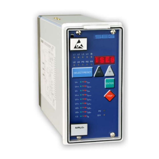
The LED marked with letters RS lights up during setting of the slave address of the device for serial data communication. The LED marked with the letters FR is alight while the fault recorder is being adjusted. If the LED is displayed, date and time are shown. Front plate Figure3.5: Front plate MRU3-1 TD_MRU3-1_09.08_GB_Rev.New... -
Page 12: Working Principle
, namely, a sampling rate of 1.25 ms for every measuring quantity, at 50 Hz. Digital circuits The essential part of the MRU3-1 relay is a powerful microcontroller. All of the operations, from the analog digital conversion to the relay trip decision, are carried out by the microcontroller digitally. -
Page 13: Selection Of Star Or Delta
Manual MRU3-1 GB Woodward 4.3.1 Selection of star or delta All six connections of the input voltage transformers are led to screw terminals. The nominal vol- tage of the device is equal to the nominal voltage of the input transformers. Dependent on the ap- plication the input transformers can be connected in either delta or star. -
Page 14: Blocking Function
Figure 4.3: Dynamic behavior of MRU3-1 functions Blocking function set in compliance with requirements: The MRU3-1 has an external blocking input. By applying the auxiliary voltage to input D8/E8, the requested protection functions of the relay are blocked (refer to chapter 5.9.1) -
Page 15: Operations And Settings
Manual MRU3-1 GB Woodward 5. Operations and settings Display Function Display shows Pressed pushbutton Corre- sponding Normal operation Measured operating values Actual measured <SELECT/RESET> one L1, L2, L3, values time for each value Transformer ratio of the CT’s (SEK) 1.01 –... - Page 16 Woodward Manual MRU3-1 GB Function Display shows Pressed pushbutton Corre- sponding Number of fault occurences S = 2, S = 4, S = 8 <SELECT/RESET> <+><-> Y = 99, M = 10, Display of date and time <SELECT/RESET> <+><-> D = 1,...
-
Page 17: Setting Procedure
Manual MRU3-1 GB Woodward Setting procedure For parameter setting a password has to be entered first (please refer to 4.4 of description "MR-Digital Multifunctional Relays"). Systemparameter 5.3.1 Display of residual voltage U as primary quantity (U prim The residual voltage can be shown as primary measuring value. For this parameter the transforma- tion ratio of the VT has to be set accordingly. -
Page 18: Setting Of Nominal Frequency
Woodward Manual MRU3-1 GB 5.3.3 Setting of nominal frequency For proper functioning it is necessary to first adjust the rated frequency (50 oder 60 Hz). It can be selected between „f = 50 Hz“, „f = 60 Hz“ or „v = 50 Hz“, “v = 60 Hz”. -
Page 19: Display Of The Activation Storage
Manual MRU3-1 GB Woodward 5.3.4 Display of the activation storage If after an activation the existing current drops again below the pickup value, e.g. U<, without a trip has been initiated, LED U< signals that an activation has occured by flashing fast. The LED keeps flashing until it is reset again (push button <RESET>). -
Page 20: Protection Parameters
Keys <+> or <-> are used to change the value and <ENTER> to store it. Note When the MRU3-1 is to be used for measuring the residual voltage in systems with isolated or compensated neutral or as generator earth fault protection, the measuring voltage has to be ap- plied to terminals A3-A4. -
Page 21: Parameter For The Fault Recorder
Woodward Parameter for the fault recorder 5.5.1 Adjustment of the fault recorder The MRU3-1 is equipped with a fault recorder (see chapter 3.1.5). Three parameters can be deter- mined. 5.5.2 Number of the fault recordings The max. recording time is 16 s at 50 Hz or 13.33 s at 60 Hz. -
Page 22: Date And Time
All faults detected by the relay are indicated on the front plate optically. For this purpose, the three LEDs (L1, L2, L3) and the four function LEDs (U<, U<<, U>, U>>) are equipped at MRU3-1. Not only fault messages are transmitted, the display also indicates the tripped protection function. If, for example an over current occurs, first the respective phase LED will light up. -
Page 23: Fault Memory
Any further faults which occur during this tripping will also be recorded, when the time differ- ence between the fault is >300 ms. The MRU3-1 is provided with a fault value recorder for max. five fault occurrences. In the event of additional trippings always the oldest data set is written over. -
Page 24: Additional Functions
5.9.1 Setting procedure for blocking the protection functions The blocking function of the MRU3-1 can be set according to requirement. By applying the aux. vol- tage to D8/E8, the functions chosen by the user are blocked. Setting of the parameter should be done as follows: •... -
Page 25: Reset
• The function of jumper J2 described in general description "MR Digital Multifunctional Re lays" does not apply for MRU3-1. For relays without assignment mode this jumper is used for parameter setting of alarm relays (activation at pickup or tripping). -
Page 26: Relay Testing And Commissioning
Woodward Manual MRU3-1 GB 6. Relay testing and commissioning The following test instructions should help to verify the protection relay performance before or dur- ing commissioning of the protection system. To avoid a relay damage and to ensure a correct relay operation, be sure that: •... -
Page 27: Checking The Set Values
Phase-to-phase voltages will be measured and evaluated. NOTE! For MRU3-1 relay used for earth fault protection be sure that the frequency set value (f=50/60) has been selected correctly according to your system frequency (50 or 60 Hz). This also applies when using the disturbance recorder (refer to Chapter 5.3.3). -
Page 28: Secondary Injection Test
6.4.2 Example of the test circuit For testing of the MRU3-1 relay, a three phase voltage source is required. Figure 6.1 shows an ex- ample of a three-phase test circuit energizing the MRU3-1 relay during test. The three phase volt- ages are applied to the relay in Y-connection. -
Page 29: Checking The Input Circuits And Measuring Functions
Manual MRU3-1 GB Woodward 6.4.3 Checking the input circuits and measuring functions Apply three voltages of rated value to the voltage input circuits (terminals A3 - A8) of the relay. Check the measured voltages, frequency and vector surge on the display by pressing the push but- ton <SELECT/RESET>... -
Page 30: Checking The External Blocking And Reset Functions
In actual service, for example, the measured voltage values on the MRU3-1 relay display may be compared phase by phase with the concerned indications of the instruments of the switchboard to verify that the relay works and measures correctly. -
Page 31: Technical Data
Manual MRU3-1 GB Woodward 7. Technical Data Measuring input circuits Rated data: Nominal voltage U 100 V, 230 V, 400 V Nominal frequency f 40 - 70 Hz Power consumption in voltage circuit: < 1 VA per phase at U... -
Page 32: Setting Ranges And Steps
Woodward Manual MRU3-1 GB Setting ranges and steps Function Para- Setting range Steps Tolerance meter Transformer ratio U (sek) 1.01...6500 0.01; 0.02; 0.05; 0.1; prim 0.2; 0.5; 1.0; 2.0; 5.0; 10; 20; 50 Rated frequency f = 50/f = 60/v = 50/v = 60... -
Page 33: Output Relays
Manual MRU3-1 GB Woodward Output relays Trip relays/change-over contacts Alarm relaya/change-over contacts MRU3 TD_MRU3-1_09.08_GB_Rev.New... -
Page 34: Order Form
Woodward Manual MRU3-1 GB 8. Order form Mains decoupling relay MRU3- Standard incl. measuring of the positive phase-sequence, negative phase-sequence and zero phase- sequence system component Rated voltage 100 V 230 V 400 V Housing (12TE) 19“-rack Flash mounting RS 485... - Page 35 Manual MRU3-1 GB Woodward Technical data subject to change without notice! Setting list MRU3-1 Project: SEG-Job.-no.: Function group: = Location: + Relay code: - Relay function: Password: Date: All settings must be checked at site and should the occasion arise, adjusted to the object/item to be protected.
- Page 36 Woodward Manual MRU3-1 GB Fault recorder Default Actual Function Unit settings settings Number of recordings Saving of the recording at the occurrence TRIP Time prior to trigger impulse 0.05 Clock Year setting year Y=00 Clock Month setting month M=01 Clock...
- Page 37 Manual MRU3-1 GB Woodward Setting of code jumpers Code jumper Default Actual Default Actual Default Actual settings settings settings settings settings settings Plugged Not plugged No function Code jumper Low/High-range for reset input Low/High-range for blockage input Default settings Actual settings...
- Page 38 Woodward Manual MRU3-1 GB Woodward SEG GmbH & Co. KG Krefelder Weg 47 ⋅ D – 47906 Kempen (Germany) Postfach 10 07 55 (P.O.Box) ⋅ D – 47884 Kempen (Germany) Phone: +49 (0) 21 52 145 1 Internet Homepage http://www.woodward-seg.com Documentation http://doc.seg-pp.com...
Need help?
Do you have a question about the MRU3-1 and is the answer not in the manual?
Questions and answers