
Subscribe to Our Youtube Channel
Related Manuals for Woodward MRI3


Summary of Contents for Woodward MRI3
- Page 1 MRI3 – Digital multifunctional relay for overcurrent protection Manual MRI3 (Revision A)
- Page 2 Woodward Manual MRI3 GB Woodward Governor Company reserves the right to update any portion of this publication at any time. Information provided by Woodward Governor Company is believed to be correct and reliable. However, no responsibility is as- sumed by Woodward Governor Company unless otherwise expressly undertaken.
-
Page 3: Table Of Contents
Manual MRI3 GB Woodward Contents Introduction and application ............... 5 Features and characteristics ..............6 Design ......................7 Connections ........................7 3.1.1 Analog input circuits ......................9 3.1.2 Output relays ........................9 ... - Page 4 6.4.6 Checking the high set element of the relay ..............48 6.4.7 Example of a test circuit for MRI3 relay with directional feature ........49 6.4.8 Test circuit earth fault directional feature ..............51 ...
-
Page 5: Introduction And Application
The protective functions of MRI3 which are implemented in only one device are summarized as fol- lows: ... -
Page 6: Features And Characteristics
Woodward Manual MRI3 GB 2. Features and characteristics Digital filtering of the measured values by using discrete Fourier analysis to suppress the high frequence harmonics and DC components induced by faults or system operations, two parameter sets, ... -
Page 7: Design
Manual MRI3 GB Woodward 3. Design Connections Phase and earth current measuring: Figure 3.1: Measuring of the phase currents for over-current- and short-circuit protection (I>,I>>) Figure 3.2: Earth-fault measuring by means of ring-core C.T. (IE) When phase-- and earth-fault current measuring are combined, the connection has to be realized as per Figure 3.1 and Figure 3.2 or Figure 3.3. - Page 8 Woodward Manual MRI3 GB Figure 3.3: Phase current measuring and earth-current detection by means of Holmgreen-circuit. This connection can be used with three existing phase current transformers when combined phase and earth-current measuring is required. Disadvantage of holmgreen-circuit: At saturation of one or more C.Ts the relay detects seeming an earth current.
-
Page 9: Analog Input Circuits
A3 and A2. See Chapter 4.5 for voltage transformer connections on isolated/compensated systems. 3.1.2 Output relays The MRI3 is equipped with 5 output relays. Apart from the relay for self-supervision, all protective functions can be optionally assigned: •... -
Page 10: Blocking Input
Woodward Manual MRI3 GB 3.1.3 Blocking input The blocking functions adjusted before will be blocked if an auxiliary voltage is connected to (terminals) D8/E8. (See chapter 5.7.1) 3.1.4 External reset input Please refer to chapter 5.10. Relay output contacts Figure 3.6:... -
Page 11: Fault Recorder
Manual MRI3 GB Woodward 3.2.1 Fault recorder The MRI3 is equipped with a disturbance value recorder which records the measured analogue values as momentary values. The momentary values iL1, iL2, iL3, i are scanned within a grid 1.25 ms (with 50 Hz) or 1.041 ms (with 60 Hz) and filed in a circulating storage. -
Page 12: Parameter Settings (See Chapter 5)
Woodward Manual MRI3 GB trigger occurence recording duration Tpre Figure 3.8: Recording scheme of the fault recorder with pre-trigger time Each memory segment has a specified storage time which permits setting of a time prior to the trigger event. Via the interface RS485 the data can be read and processed by means of a PC with HTL/PL-Soft4. - Page 13 Manual MRI3 GB Woodward Protection parameter Relay type MRI3- IRER IRSR IRXR 2 parameter sets I> CHAR I> tI> 0s /60s I>> I>> E> warn/trip CHAR I 0s / 60s E>> IE>> sin/cos soli/resi tCBFP Block/Trip Table 3.2: Protection parameters of the different relay types.
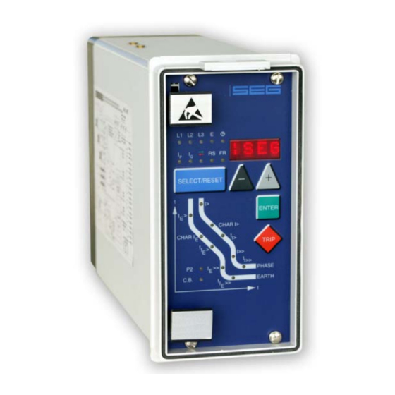
- Page 14 Woodward Manual MRI3 GB Front plates Figure 3.9: Front plate MRI3-I Figure 3.10: Front plate MRI3-E/X DOK-TD-MRI3 Rev.A...
- Page 15 Manual MRI3 GB Woodward Figure 3.11: Front plate MRI3-IR Figure 3.12: Front plate MRI3-ER/XR DOK-TD-MRI3 Rev.A...
- Page 16 Woodward Manual MRI3 GB Figure 3.13: Front plate MRI3-SR Figure 3.14: Front plate MRI3-IRER/IRXR and MRI3-IER/IXR DOK-TD-MRI3 Rev.A...
-
Page 17: Leds
The LEDs left from the display are partially bi-colored, the green indicating measuring, and the red fault indication. MRI3 with directional feature have a LED (green- and red arrow) for the directional display. At pickup/trip and parameter setting the green LED lights up to indicate the forward direction, the red LED indicates the backward direction. -
Page 18: Working Principle
Figure 4.1: Block diagram Digital circuits The essential part of the MRI3 relay is a powerful microcontroller. All of the operations, from the analog digital conversion to the relay trip decision, are carried out by the microcontroller digitally. The relay program is located in an EPROM (Electrically-Programmable-Read-Only-Memory). With this program the CPU of the microcontroller calculates the three phase currents and ground current in order to detect a possible fault situation in the protected object. -
Page 19: Directional Feature
Only when the timer is at zero again, the MRI3 recognizes the reversal in direction. The switch-over time is max. 2 s. The activation delays tl> and tl>> are not affected by the delayed recognition of direction. - Page 20 0.25 kA and for the I>> stage 1 kA. All devices have the same setting and will, if set to “Forward”, recognize the direction in relation to the forward direction of the line. The critical point here is the MRI3 No. 1. Using delay action in directional recognition, it is possible to prevent shut- down of the fault-free line.
- Page 21 Manual MRI3 GB Woodward If line impedance and internal resistance of the generator is only ohmic: If line impedance and internal resistance of the generator is only inductive: The maximum sensitivity angle corresponds to the R/L component. DOK-TD-MRI3 Rev.A...
- Page 22 ±90°, so that a reliable direction decision can be achieved in all faulty cases. Figure 4.6: TRIP/NO-TRIP region for directional element in MRI3. In this case the foreward direction is defined as TRIP region and the backward direction as NO-TRIP region.
-
Page 23: Earth Fault Protection
Earth fault protection 4.4.1 Generator stator earth fault protection With the generator neutral point earthed as shown in Figure 4.7 the MRI3 picks up only to phase earth faults between the generator and the location of the current transformers supplying the relay. -
Page 24: Earth-Fault Directional Feature (Er/Xr-Relay Type)
(active or reactive current component for cos φ or sin φ method) for E> E>> ER-relay types can be adjusted from 0.01 to 0.45 x I . For relay type MRI3-XR these pick-up val- ues can be adjusted from 0.1 to 4.5% I Adjust- Application... - Page 25 Manual MRI3 GB Woodward Figure 4.9: Phase position between the residual voltage and zero sequence current for faulted and non-faulted lines in case of isolated systems (sin φ) - residual voltage - zero sequence current - capacitive component of zero sequence cur-rent - resistive component of zero sequence current By calculating the reactive current component (sin φ...
-
Page 26: Determining Earth Short-Circuit Fault Direction (Sr/Yr-Relay Type)
Woodward Manual MRI3 GB By means of an efficient digital filter harmonics and fault transients in the fault current are sup- pressed. Thus, the uneven harmonics which, for instance, are caused an electric arc fault, do not impair the protective function. -
Page 27: Resistance - Earthed System
Manual MRI3 GB Woodward 4.6.2 Resistance – earthed system Most faults in a resistance-earthed system are pre-dominantly ohmic in character, with a small in- ductive part. The characteristic angle for these types of system has therefore been set at +170° in relation to the zero sequence voltage U0 (see Figure 4.12). -
Page 28: Connection Possibilities Of The Voltage Transformers For Sr Relay Types
The low power consumption in the current circuit of MRI3, namely <0.2 VA, has a positive effect on the selection of current transformers. It implies that, if an electromechanical relay is replaced by MRI3, a high accuracy limit factor is automatically obtained by using the same current transformer. -
Page 29: Operation And Settings
Manual MRI3 GB Woodward 5. Operation and settings Display Function Display shows Pressed push button Corresponding Normal operation Measured operating values Actual measured val- <SELECT/RESET> one time L1, L2, L3, E, U E> E> ues (related to I for each... -
Page 30: Setting Procedure
Woodward Manual MRI3 GB Function Display shows Pressed push button Corresponding Save parameter! SAV! <ENTER> for about 3 s Software Version 1. part (e. g D01-) <TRIP> one time for each 2. part (e.g. 8.00) part Manual trip TRI? <TRIP>three times... -
Page 31: System Parameter
The parameter of this function is to be set in the same way as that described under 5.3.1. If the pa- rameter is not set to "SEK", to relay types MRI3-X and MRI3-XR it applies too, that the measuring value is shown as primary current in ampere. Apart from that the indication refers to % of I 5.3.3 Display of residual voltage U... -
Page 32: Display Of The Activation Storage (Flsh/Nofl)
Woodward Manual MRI3 GB 5.3.6 Display of the activation storage (FLSH/NOFL) If after an activation the existing current drops again below the pickup value, e.g. I>, without a trip has been initiated, LED I> signals that an activation has occurred by flashing fast. The LED keeps flashing until it is reset again (push button <RESET>). -
Page 33: Parameter Protection
When the time delay or the time multiplier is set out of range (Text "EXIT" appears on the display), the low set element of the overcurrent relay is blocked. The "WARN"-relay will not be blocked. For the MRI3-version with directional feature, the different trip time delays or the time multipliers can be chosen for forward and backward faults. -
Page 34: Reset Setting For All Tripping Characteristics In The Phase Current Path
Woodward Manual MRI3 GB 5.4.4 Reset setting for all tripping characteristics in the phase current path To ensure tripping, even with recurring fault pulses shorter than the set trip delay, the reset mode for inverse time tripping characteristics can be switched over. If the adjustment tRST is set at 60 s, the tripping time is only reset after 60 s faultless condition. -
Page 35: Warn/Trip Changeover (All Earth Fault-Relay Type)
Manual MRI3 GB Woodward 5.4.10 WARN/TRIP changeover (all earth fault-relay type) A detected earth fault can be parameterized as follows. After delay time. a) "warn" only the alarm relay trips b) "trip" the trip relay trips and tripping values are stored. -
Page 36: Soli/Resi Changeover (Sr/Yr-Relay Type)
Woodward Manual MRI3 GB 5.4.17 SOLI/RESI changeover (SR/YR-relay type) Depending on the method of neutral-point connection of the system to be protected, the directional element for the earth-current circuit must be set to "SOLI" (= solidly earthed) or "RESI" = (resis- tance earthed). -
Page 37: Fault Recorder
Fault recorder 5.5.1 Adjustment of the fault recorder The MRI3 is equipped with a fault recorder (see chapter 0). Three parameters can be determined. 5.5.2 Number of the fault recordings The max. recording time is 16 s at 50 Hz or 13.33 s at 60 Hz. -
Page 38: Adjustment Of The Clock
5.7.1 Blocking the protection functions and assignment of the output relays Blocking of the protective functions: The MRI3-IHE is equipped with a blocking function that can be parameterized arbitrary. Connecting supply voltage to terminals D8/E8 blocking of those functions which were selected by the user takes place. - Page 39 Assignment of the output relays: Unit MRI3 has five output relays. The fifth output relay is provided as permanent alarm relay for self supervision is normally on. Output relays 1 - 4 are normally off and can be assigned as alarm or tripping relays to the current functions which can either be done by using the push buttons on the front plate or via serial interface RS485.
-
Page 40: Setting Value Calculation
Woodward Manual MRI3 GB Relay function Output relays Display- Lighted indication I> (V) alarm _ 2 _ _ I>; →← green tI> (V) tripping 1 _ _ _ ; →← I> grün I> (R) alarm _ 2 _ _ I>; →← red tI>... -
Page 41: Inverse Time Overcurrent Element
(LED E green, LED IE> yellow and LED UE> yellow). * only in case that the directional option is built in. The indicated current measuring values refer to rated current. (For MRI3-XR/X relays the indicated measuring values refer to % of I... -
Page 42: Units Of The Measuring Values Displayed
Woodward Manual MRI3 GB 5.9.2 Units of the measuring values displayed The measuring values can optionally be shown in the display as a multiple of the "sec" rated value (xln) or as primary current (A). According to this the units of the display change as follows:... - Page 43 Manual MRI3 GB Woodward Earth current (normal): Indication as Range Unit Secondary current .000 – 15.0 x In Active portion I ±.00 – 15 x In Reactive portion I ±.00 – 15 x In (E/SR/ER types) Primary earth current .000 – 999.
-
Page 44: Indication Of Fault Data
When the relay is energized or trips, all fault data and times are stored in a non-volatile memory manner. The MRI3 is provided with a fault value recorder for max. five fault occurrences. In the event of additional trip-pings always the oldest data set is written over. -
Page 45: Reset
Manual MRI3 GB Woodward 5.10 Reset Unit MRI3 has the following three possibilities to reset the display of the unit as well as the output relay at jumper position J3=ON. Manual Reset Pressing the push button <SELECT/RESET> for some time (about 3 s) Electrical Reset ... -
Page 46: Relay Testing And Commissioning
Woodward Manual MRI3 GB 6. Relay testing and commissioning The test instructions following below help to verify the protection relay performance before or dur- ing commissioning of the protection system. To avoid a relay damage and to ensure a correct relay operation, be sure that: ... -
Page 47: Secondary Injection Test
6.4.2 Example of test circuit for MRI3 relays without directional feature For testing MRI3 relays without directional feature, only current input signals are required. Figure 6.1 shows a simple example of a single phase test circuit with adjustable current energizing the MRI3 relay under test. -
Page 48: Checking The Input Circuits And Measured Values
RMS-metering instrument, a greater deviation may be observed if the test current contains harmon- ics. Because the MRI3 relay measures only the fundamental component of the input signals, the harmonics will be rejected by the internal DFFT-digital filter. Whereas the RMS-metering instrument measures the RMS-value of the input signals. -
Page 49: Example Of A Test Circuit For Mri3 Relay With Directional Feature
(current) and phase angle shall be appropriately varied. MRI3 is a three phase directional time overcurrent relay with relay connection angle of 0°. The re- lay input currents and their corresponding reference voltages are shown in Table 6.1 (also refer to 4.3):... - Page 50 Woodward Manual MRI3 GB Determining the change in direction The angle of greatest sensitivity for determining the phase direction is adjustable between 15° and 83°. Consequently, the greatest sensitivity is achieved with setting 49° if the input current leads the input voltage by 49°.
-
Page 51: Test Circuit Earth Fault Directional Feature
Figure 6.3 shows an example of a single phase test circuit with ad- justable voltage and current energizing the MRI3 relay under test. For testing a relay with earth fault directional feature, one of the input energizing quantity (voltage) shall be applied to the relay with a constant value within its effective range. -
Page 52: Checking The External Blocking And Reset Functions
Woodward Manual MRI3 GB 6.4.9 Checking the external blocking and reset functions By means of the external blocking input, it is possible to block all protective functions. To give an example, the blocking function of the phase current high set element is described. -
Page 53: Primary Injection Test
In case of a MRI3 relay with directional feature, the active and reactive parts of the measured currents may be checked and the actual power factor may be calculated and compared it with the cosφ... -
Page 54: Technical Data
Woodward Manual MRI3 GB 7. Technical data Measuring input circuits Rated data: Nominal current I 1 A or 5 A Nominal voltage U 100 V, 230 V, 400 V Nominal frequency f 50 Hz; 60 Hz adjustable Power consumption in... -
Page 55: Setting Ranges And Steps
Manual MRI3 GB Woodward Setting ranges and steps System parameter Setting range Step Tolerance (SEK) 0.001; 0.002; 0.005; 0.01; 0.02; prim 0.001...50.0KA 0.05; 0.1; 0.2 Eprim (SEK) 1.01...6500 0.01; 0.02; 0.05; 0.1; 0.2; 0.5; 1; E> 2; 5; 10; 20; 50 prim 7.3.1 Time overcurrent protection (I-Type) -
Page 56: Earth Fault Protection (Er/Xr-Type)
Woodward Manual MRI3 GB 7.3.4 Earth fault protection (ER/XR-Type) Setting range Step Tolerance 5% from set value or 0.01...0.45 x I (EXIT) 0.001; 0.002; 0.005; 0.01 x I E> (ER) 0.1...4.5% I (EXIT) 0.01%; 0.02%; 0.05%; 0.1% I 0.3% I (ER);... -
Page 57: Inverse Time Overcurrent Protection Relay
Manual MRI3 GB Woodward 7.3.9 Inverse time overcurrent protection relay According to IEC 255-4 or BS 142 Normal Inverse (Type A) 0.14 · Very Inverse (Type B) 13.5 · Extremely Inverse (Type C) · Long Time Inverse · RI-Inverse Time ·... -
Page 58: Direction Unit For Phase Overcurrent Relay
Woodward Manual MRI3 GB 7.3.10 Direction unit for phase overcurrent relay Directional sensitivity for voltage input circuit: <0.025% U (phase-to-phase voltage) at I = 1 x I Connection angle: 90° Characteristic angle: 15°, 27°, 38°, 49°, 61°, 72°, 83° Effective angle: ±78°... -
Page 59: Inverse Time Characteristics
Manual MRI3 GB Woodward Inverse time characteristics 1000 I> 10.0 t[s] 0.05 5 6 7 8 910 Figure 7.1: Normal Inverse (Type A) 1000 I> t[s] 10.0 0.05 5 6 7 8 910 Figure 7.2: Very Inverse (Type B) DOK-TD-MRI3 Rev.A... - Page 60 Woodward Manual MRI3 GB 1000 t[s] I> 10.0 0.05 0.05 0.01 5 6 7 8 910 Figure 7.3: Extremely Inverse (Type C) I> 10.0 t[s] 0.05 5 6 7 8 910 Figure 7.4: RI-Inverse DOK-TD-MRI3 Rev.A...
- Page 61 Manual MRI3 GB Woodward 10000 1000 I> t[s] 10.0 0.05 5 6 7 8 910 Figure 7.5: Long Time Inverse I> 10.0 t[s] 0.05 5 6 7 8 910 Figure 7.6: RXIDG-characteristic DOK-TD-MRI3 Rev.A...
-
Page 62: Output Contacts
Woodward Manual MRI3 GB I> I> 0.02 0.02 t[s] > > 0.03 0.03 I>> I>> 40 40 >> >> 0.03 0.03 0.01 Figure 7.7: Definite time overcurrent relay Output contacts Number of relays: dependent on relay type Contacts: 2 change-over contacts for trip relay... -
Page 63: Order Form
Manual MRI3 GB Woodward 8. Order form Time overcurrent-/ MRI3- Earth fault current relay 3-phase current I>, I>> none Rated current Phase fault directional feature none Rated voltage 100 V 230 V 400 V Earth current measuring none Rated current... - Page 64 Woodward Manual MRI3 GB Setting list MRI3 Note ! All settings must be checked at site and should the occasion arise, adjusted to the object / item to be protected. Project: Woodward job.-no.: Function group: = Location: + Relay code: -...
- Page 65 Manual MRI3 GB Woodward Fault recorder Function Unit Default Actual settings settings Number of recordings Saving of the recording at the occurrence TRIP Time prior to trigger impulse 0,05 Year settings Year Y = 00 Month settings Month M=00 ...
- Page 66 Software version: D01-9.03 (MRI3-ER; -IER; -IRER) D20-3.03 (MRI3-XR; -IXR; -IRXR) D24-2.03 (MRI3-X; -IX; -IXR) D00-9.04 (MRI3; I; E; IE; -IR; SR; -IRE; -ISR; -IRSR) D18-9.00 (MRI3; -IRYR; -IYR; -YR) Modbus version number: D51-2.12 (MRI3-ER-M; -IER-M; -IRER-M) D70-2.12 (MRI3-XR-M; -IXR-M; -IRXR-M) D74-2.12 (MRI3-X-M;...
- Page 67 Manual MRI3 GB Woodward DOK-TD-MRI3 Rev.A...
- Page 68 Woodward Manual MRI3 GB Woodward Kempen GmbH Krefelder Weg 47 D – 47906 Kempen (Germany) Postfach 10 07 55 (P.O.Box) D – 47884 Kempen (Germany) Phone: +49 (0) 21 52 145 1 Internet www.woodward.com Sales Phone: +49 (0) 21 52 145 216 or 342 Telefax: +49 (0) 21 52 145 354 e-mail: salesEMEA_PGD@woodward.com...
Need help?
Do you have a question about the MRI3 and is the answer not in the manual?
Questions and answers