
Subscribe to Our Youtube Channel
Related Manuals for Woodward easYprotec-1000 Series


Summary of Contents for Woodward easYprotec-1000 Series
- Page 1 Series Manual Multifunction Relay easYprotec-1410 Release 1.0302 Document ID: 37541B, Revision B - Build 53231...
- Page 2 This is no translation but the original Technical Manual in English. Designed in Germany. Woodward GmbH Handwerkstr. 29 70565 Stuttgart Germany Telephone: +49 (0) 711 789 54‑510 Fax: +49 (0) 711 789 54‑101 E-mail: stgt-info@woodward.com Internet: http://www.woodward.com © 2023 Woodward GmbH. All rights reserved. easYprotec-1000 Series 37541B...
- Page 3 • USB connector: DPC-USB direct configuration cable – P/N 5417-1251 • • RS-232 connector: DPC-RS-232 direct configuration cable – P/N 5417-557 • The easYprotec-1000 Series are multifunction relays which combine measuring and protection capabilities into one single system. 37541B easYprotec-1000 Series...
- Page 4 PLC. For a listing of additional applications and setups please refer to chapter ╚═▷ “6 Application”. Versions The easYprotec-1000 Series multifunction relays are available in different versions. The differences are listed below. easYprotec-1000 Series 37541B...
- Page 5 Brief Overview easYprotec-1000 Series easYprotec-1410 easYprotec-1410-[x] [1] = 120 Vac [7] = 690 Vac Measuring voltage Scope of delivery The following parts are included in the scope of delivery. Please check prior to the installation that all parts are present.
-
Page 6: Table Of Contents
..............32█ easYprotec-1000 Series 37541B... - Page 7 ..............80█ 37541B easYprotec-1000 Series...
- Page 8 ............... . 90█ easYprotec-1000 Series 37541B...
-
Page 9: General Information
Safety instructions are marked with symbols in these instructions. The safety instructions are always introduced by signal words that express the extent of the danger. DANGER! This combination of symbol and signal word indicates an immediately-dangerous situation that could cause death or severe injuries if not avoided. 37541B easYprotec-1000 Series... -
Page 10: Copyright And Disclaimer
References to sections of these instructions and to other relevant documents • Listing without fixed sequence »Buttons« Operating elements (e.g. buttons, switches), display elements (e.g. signal lamps) »Display« Screen elements (e.g. buttons, programming of function keys) Copyright And Disclaimer Disclaimer easYprotec-1000 Series 37541B... -
Page 11: Service And Warranty
All information and instructions in this operating manual have been provided under due consideration of applicable guidelines and regulations, the current and known state of the art, as well as our many years of in-house experience. Woodward GmbH assumes no liability for damages due to: •... -
Page 12: Personnel
The workforce must only consist of persons who can be expected to carry out their work reliably. Persons with impaired reactions due to, for example, the consumption of drugs, alcohol, or medication are prohibited. When selecting personnel, the age-related and occupation-related regulations governing the usage location must be observed. easYprotec-1000 Series 37541B... -
Page 13: General Safety Notes
• constitute "misuse" and/or "negligence" within the meaning of the product warranty • thereby excluding warranty coverage for any resulting damage • invalidate product certifications or listings. • Electrostatic discharge ⚙ ᐳ • Protective equipment: ESD wrist band 37541B easYprotec-1000 Series... -
Page 14: Protective Equipment And Tools
For additional information on how to prevent damage to electronic components caused by improper handling, read and observe the precautions in: • "Woodward manual 82715, Guide for Handling and Protection of Electronic Controls, • Printed Circuit Boards, and Modules". - Page 15 Tools Use of the proper tools ensures successful and safe execution of tasks presented in this manual. Specific required tools are listed in each individual set of instructions. The cumulative required tools are detailed below: 37541B easYprotec-1000 Series...
-
Page 16: System Overview
• • ╚═▷ “5 Operation” provides information on how to access the unit remotely using the ToolKit software provided by Woodward. • • ╚═▷ “6 Application” provides application examples as well as instructions for the corresponding required configuration. -
Page 17: Hardware Interfaces (Terminals)
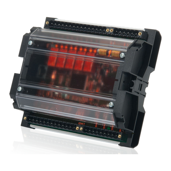
Table 1: LED (Ready for operation) Hardware Interfaces (Terminals) The easYprotec-1410 (╚═▷ Fig. 5) provides the following terminals. Fig. 5: easYprotec-1000 Series (housing) Voltage PT terminal Relay outputs terminal Service port connector (USB/RS-232) Optional configuration cable for ToolKit configuration software and external extensions/ applications required: •... -
Page 18: Measuring Values
However the frequency is still measured correctly even if voltage is only applied to one phase. Phase angle Measuring of the phase angle between the single wye voltages. easYprotec-1000 Series 37541B... -
Page 19: Installation
• Connected inductances (e.g. operating current coils, undervoltage tripping devices, • auxiliary contactors, and/or power contactors) must be wired with an appropriate interference protection. Wire sizes mm² AWG mm² AWG mm² AWG mm² AWG mm² AWG mm² 0.05 0.38 600MCM 300 0.08 750MCM 400 37541B easYprotec-1000 Series... -
Page 20: Terminal Allocation
350MCM 185 0.34 500MCM 240 Table 2: Conversion chart - wire sizes 3.2.1 Terminal Allocation General notes The device terminals are allocated as follows: • Plastic housing - shown in • ╚═▷ Fig. 7 Fig. 7: Plastic housing easYprotec-1000 Series 37541B... -
Page 21: Wiring Diagram
3 Installation 3.2.2 Wiring Diagram 3.2.2 Wiring Diagram Fig. 8: Wiring diagram 3.2.3 Power Supply Schematic and terminals Fig. 9: Power supply - wiring 37541B easYprotec-1000 Series... -
Page 22: Voltage Measuring
General notes NOTICE! Versions The easYprotec-1000 Series multifunction relays are available in different versions. Please make sure to use the description which is valid for your device. Woodward recommends protecting the voltage measuring inputs with slow-acting fuses rated for 2 to 6 A. - Page 23 Measuring voltage L1 120 Vac 2.5 mm² Measuring voltage L2 120 Vac 2.5 mm² Measuring voltage L3 120 Vac 2.5 mm² Measuring voltage N 120 Vac 2.5 mm² Table 5: Voltage measuring - 120 Vac - terminal assignment 37541B easYprotec-1000 Series...
-
Page 24: Parameter Setting '3Ph 4W' (3-Phase, 4-Wire)
Measuring inputs - 3Ph 4W Terminal assignment 3Ph 4W Wiring terminals Rated voltage 120 V (50 to 130 V 690 V (131 to 690 V eff. eff. (range) Measuring range 0 to 150 Vac 0 to 800 Vac (max.) Terminal Phase easYprotec-1000 Series 37541B... -
Page 25: Parameter Setting '3Ph 3W' (3-Phase, 3-Wire)
Measuring inputs - 3Ph 3W Terminal assignment 3Ph 3W Wiring terminals Rated voltage 120 V (50 to 130 V 690 V (131 to 690 V eff. eff. (range) Measuring range 0 to 150 Vac 0 to 800 Vac (max.) Terminal Phase 37541B easYprotec-1000 Series... -
Page 26: Parameter Setting '1Ph 3W' (1-Phase, 3-Wire)
Measuring inputs - 1Ph 3W Terminal assignment 1Ph 3W Wiring terminals Rated voltage 120 V (50 to 130 V 690 V (131 to 690 V eff. eff. (range) Measuring range 0 to 150 Vac 0 to 800 Vac (max.) easYprotec-1000 Series 37541B... -
Page 27: Parameter Setting '1Ph 2W' (1-Phase, 2-Wire)
• Please note to configure and wire the device consistently. • 3.2.4.4.1 '1Ph 2W' Phase-Neutral Measuring Generator windings Table 9: Generator windings - 1Ph 2W (phase neutral) Measuring inputs Fig. 15: Measuring inputs - 1Ph 2W (phase neutral) 37541B easYprotec-1000 Series... - Page 28 Measuring range 0 to 150 Vac 0 to 800 Vac (max.) Terminal Phase 3.2.4.4.2 '1Ph 2W' Phase-Phase Measuring Generator windings Table 10: Generator windings - 1Ph 2W (phase-phase) Measuring inputs Fig. 16: Measuring inputs - 1Ph 2W (phase-phase) easYprotec-1000 Series 37541B...
-
Page 29: Relay Outputs
Schematic and terminals Fig. 17: Relay outputs - schematic Terminal Description N.O. CommonN.C. Form C Relay output [R mm² Relay output [R mm² Relay output [R Fixed to "Ready for operation" mm² 37541B easYprotec-1000 Series... -
Page 30: Service Port
Service port connector Fig. 18: Service port connector (RJ-45) The Woodward specific service port is a connector (RJ-45) to extend the interfaces of the controller. The service port can be only used in combination with an optional Woodward direct configuration cable (DPC). - Page 31 0.5 m. DPC-RS-232 direct configuration cable Use the DPC-RS-232 direct configuration cable if you want to connect the Woodward controller to an external device (master) which is equipped with an RS-232 port. Order item number: •...
-
Page 32: Configuration
╚═▷ “5.1 Access Via PC (ToolKit)” for details about the operation of the device via ToolKit. Fig. 21: Homepage Configuration 4.2.1 Measurement General notes The setpoints for specific parameters will differ depending upon the hardware version, indicated on the data plate. easYprotec-1000 Series 37541B... - Page 33 1851 Voltage [3Ph 4W] Measurement is performed Line-Neutral (WYE measuring connected system) and Line-Line (Delta connected system). The protection depends on the setting of parameter 1770. 37541B easYprotec-1000 Series...
- Page 34 The protection depends on the setting of parameter 1770. Measurement, display, and protection are adjusted according to the rules for single-phase systems. Monitoring refers to the following voltages: • VL13 (parameter 1770 configured to • "Phase-phase") easYprotec-1000 Series 37541B...
- Page 35 The unit can either monitor the wye voltages monitoring (phase-neutral) or the delta voltages (phase- phase). The monitoring of the wye voltage is above all necessary to avoid earth-faults in a compensated or isolated network resulting in the tripping of the voltage protection. 37541B easYprotec-1000 Series...
- Page 36 1800 PT secondary 50 to 800 V The secondary source voltage in V, which is rated volt. used as a reference figure for related [690 V] functions. (Potential transformer easYprotec-1000 Series 37541B...
-
Page 37: Discrete Outputs
The relay will be energized when an alarm function occurs. 6921 The relay will be de-energized when an alarm [x = 1 to 2] occurs. Notes The fallback delay of the relays can be configured with parameter 8855. 37541B easYprotec-1000 Series... -
Page 38: Monitoring
(parameter 1851) is configured. This controller provides the user with two alarm levels for overvoltage. Both alarms are definite time alarms. Monitoring for overvoltage faults is performed in two steps. The diagram listed below shows a frequency trend and the associated pickup times and length of the alarms. easYprotec-1000 Series 37541B... - Page 39 [Default] 2000 Monitoring [On] Overvoltage monitoring is carried out according to the following parameters. 2006 Monitoring is performed at two levels. Both values may be configured independent from each other (prerequisite: Level 1 limit < limit 2). 37541B easYprotec-1000 Series...
-
Page 40: Undervoltage (Level 1 & 2) Ansi# 27
Voltage is monitored according to how the parameter "Voltage measuring" (parameter 1851) is configured. This controller provides the user with two alarm levels for undervoltage. Both alarms are definite time alarms. Monitoring for undervoltage faults is performed in two steps. easYprotec-1000 Series 37541B... - Page 41 Parameter CL Setting range Description [Default] 2050 Monitoring [On] Undervoltage monitoring is carried out according to the following parameters. 2056 Monitoring is performed at two levels. Both values may be configured independent from 37541B easYprotec-1000 Series...
- Page 42 "None" is configured here, no relay is activated 2051: [Relay 1] in this case. 2057: [Relay 2] Notes Whether the relay is energized or de-energized depends on the configuration of the relay function (parameter 6920 and 6921). easYprotec-1000 Series 37541B...
-
Page 43: Overfrequency (Level 1 & 2) Ansi# 81O
Fig. 26: Overfrequency monitoring The hysteresis is 0.05 Hz. The parameter limits listed below have identical setting ranges. Each parameter may be configured with different settings to create unique trip characteristics for specific thresholds. 37541B easYprotec-1000 Series... - Page 44 "None" is configured here, no relay is activated 1901: [Relay 1] in this case. 1907: [Relay 2] Notes Whether the relay is energized or de-energized depends on the configuration of the relay function (parameter 6920 and 6921). easYprotec-1000 Series 37541B...
-
Page 45: Underfrequency (Level 1 & 2) Ansi# 81U
Fig. 27: Underfrequency monitoring The hysteresis is 0.05 Hz. The parameter limits listed below have identical setting ranges. Each parameter may be configured with different settings to create unique trip characteristics for specific thresholds. 37541B easYprotec-1000 Series... - Page 46 "None" is configured here, no relay is activated 1951: [Relay 1] in this case. 1957: [Relay 2] Notes Whether the relay is energized or de-energized depends on the configuration of the relay function (parameter 6920 and 6921). easYprotec-1000 Series 37541B...
-
Page 47: Voltage Asymmetry (Level 1 & 2)
Fig. 28: Voltage asymmetry monitoring The hysteresis is 0.5 % of the primary transformer delta voltage. This monitoring function is only enabled if "Voltage measuring" (parameter 1851) is configured to "3Ph 4W" or "3Ph 3W". 37541B easYprotec-1000 Series... -
Page 48: Phase Shift
A vector/phase shift is defined as the sudden variation of the voltage curve which may be caused by a major source load change. The unit measures the duration of a cycle, where a new measurement is started with each voltage passing through zero. The measured cycle duration will be compared with easYprotec-1000 Series 37541B... - Page 49 (parameter 3054) in at least one of the three phases. 3-phase During three-phase voltage phase/vector shift monitoring, tripping occurs only if the phase/ vector shift exceeds the specified threshold value (parameter 3055) in all three phases within 2 cycles. Notes 37541B easYprotec-1000 Series...
-
Page 50: Df/Dt (Rocof)
(rate of change of frequency) monitoring measures the stability of the frequency. The frequency of a source will vary due to changing loads and other effects. The rate of these frequency changes due to the load variances is relatively high compared to those of a large network. easYprotec-1000 Series 37541B... -
Page 51: Voltage Increase
10 minute moving average. The function is only active, if the frequency is larger than 60 % of the nominal frequency. If "Voltage measuring" (parameter 1851) is configured to a three-phase measurement, the slow voltage increase alarm is monitoring 37541B easYprotec-1000 Series... - Page 52 If the average voltage over 10 minutes is higher, the specified relay will be energized. Notes This value refers to the "Rated voltage" (parameter 1766). 8849 If the 10 minute voltage averages of all phases characteristics exceed the limit, the monitoring is tripping. easYprotec-1000 Series 37541B...
-
Page 53: Time-Dependent Voltage 1
FRT (fault ride-through) monitoring function according to the grid code requirements for wind turbines. The time points should always have an ascending order. The fallback threshold should always be configured to a value higher/lower than the init threshold. 37541B easYprotec-1000 Series... - Page 54 0.15 s → 70.0 % 0.70 s → 70.0 % 1.50 s → 90.0 % 3.00 s → 90.0 % 4.00 s → 90.0 % Fallback 90.0 % voltage Initial 80.0 % threshold Fallback 1.00 s time easYprotec-1000 Series 37541B...
- Page 55 (parameter 4970) for proper operation. 4961 Time point {x} 0.00 to 320.00 s The time values of time-dependent voltage monitoring time points are configured here. 4962 [x = 1 to 7] 4961: [0.00 s] 4963 4962: [0.15 s] 37541B easYprotec-1000 Series...
-
Page 56: Time-Dependent Voltage 2
If the measured voltage falls below/ exceeds the configured "Fallback threshold" (parameter 4998) for at least the configured "Fallback time" (parameter 4988), the time-dependent voltage monitoring sequence will be reset. easYprotec-1000 Series 37541B... - Page 57 STI (short-term interruption) monitoring function according to the grid code requirements for wind turbines. The time points should always have an ascending order. The fallback threshold should always be configured to a value higher/lower than the init threshold. 37541B easYprotec-1000 Series...
- Page 58 1.50 s → 90.0 % 10.00 s → 90.0 % 20.00 s → 90.0 % 30.00 s → 90.0 % 40.00 s → 90.0 % Fallback 90.0 % voltage Initial 80.0 % threshold Fallback 1.00 s time easYprotec-1000 Series 37541B...
- Page 59 (parameter 4990) for proper operation. 4981 Time point {x} 0.00 to 320.00 s The time values of time-dependent voltage monitoring time points are configured here. 4982 [x = 1 to 7] 4981: [0.00 s] 4983 4982: [0.15 s] 37541B easYprotec-1000 Series...
-
Page 60: Time-Dependent Voltage 3
If the measured voltage falls below/ exceeds the configured "Fallback threshold" (parameter 9156) for at least the configured "Fallback time" (parameter 9147), the time-dependent voltage monitoring sequence will be reset. easYprotec-1000 Series 37541B... - Page 61 FRT (fault ride-through) monitoring function according to the grid code requirements for wind turbines. The time points should always have an ascending order. The fallback threshold should always be configured to a value higher/lower than the init threshold. 37541B easYprotec-1000 Series...
- Page 62 0.15 s → 70.0 % 0.70 s → 70.0 % 1.50 s → 90.0 % 3.00 s → 90.0 % 4.00 s → 90.0 % Fallback 90.0 % voltage Initial 80.0 % threshold Fallback 1.00 s time easYprotec-1000 Series 37541B...
- Page 63 (parameter 9148) for proper operation. 9140 Time point {x} 0.00 to 320.00 s The time values of time-dependent voltage monitoring time points are configured here. 9141 [x = 1 to 7] 9140: [0.00 s] 9142 9141: [0.15 s] 37541B easYprotec-1000 Series...
-
Page 64: Time-Dependent Voltage 4
If the measured voltage falls below/ exceeds the configured "Fallback threshold" (parameter 9173) for at least the configured "Fallback time" (parameter 9164), the time-dependent voltage monitoring sequence will be reset. easYprotec-1000 Series 37541B... - Page 65 STI (short-term interruption) monitoring function according to the grid code requirements for wind turbines. The time points should always have an ascending order. The fallback threshold should always be configured to a value higher/lower than the init threshold. 37541B easYprotec-1000 Series...
- Page 66 1.50 s → 90.0 % 10.00 s → 90.0 % 20.00 s → 90.0 % 30.00 s → 90.0 % 40.00 s → 90.0 % Fallback 90.0 % voltage Initial 80.0 % threshold Fallback 1.00 s time easYprotec-1000 Series 37541B...
- Page 67 (parameter 9165) for proper operation. 9157 Time point {x} 0.00 to 320.00 s The time values of time-dependent voltage monitoring time points are configured here. 9158 [x = 1 to 7] 9157: [0.00 s] 9159 9158: [0.15 s] 37541B easYprotec-1000 Series...
-
Page 68: System Management
(parameter 6920 and 6921). System Management 4.4.1 Factory Settings Parameter CL Setting range Description [Default] 1704 Factory default Enables the parameter "Reset factory default settings values" (parameter 1701). [No] Disables the parameter "Reset factory default values" (parameter 1701). easYprotec-1000 Series 37541B... -
Page 69: Password System
The user may also change the password for level CL1. Access granted by this password expires two hours after the password has been entered and the user is returned 37541B easYprotec-1000 Series... -
Page 70: Password Entry
The password to configure the device needs to be entered here. 4.4.4 Passwords General notes The values from parameter 10411 to parameter 10415 are not readable in ToolKit if the actual code level is lower than the parameters code level. easYprotec-1000 Series 37541B... - Page 71 "Temporary level code Supercommissioning" is defined in this parameter. 10411 Supercommissioning 0 to 9999 The password for the code level level code "Supercommissioning" is defined in this parameter. Refer to ╚═▷ “4.4.2 Password System” default values. 37541B easYprotec-1000 Series...
-
Page 72: Operation
• ╚═▷ “5.1.1 Install ToolKit” Access Via PC (ToolKit) Version Woodward’s ToolKit software is required to access the unit via PC. • Required version: {?software.version} or higher • • For information on how to obtain the latest version see •... -
Page 73: Install Toolkit Configuration Files
The latest version of the ToolKit software can be obtained from our website. ⚙ ᐳ To get the software from the website: 1. ▷ Go to ══▷ http://www.woodward.com/software/configfiles Insert the part number (P/N) and revision of your device into the corresponding fields. 2. ▷ Select "ToolKit" in the »application type« list. 3. ▷... -
Page 74: Configure Toolkit
P/N1 = Part number of the unit • • P/N2 = Part number of the software in the unit 5.1.3 Configure ToolKit ⚙ ᐳ To change ToolKit settings: 1. ▷ Fig. 34: Tools menu Select [Tools / Options]. easYprotec-1000 Series 37541B... - Page 75 Adjust settings as required. For more information on the individual settings refer to the ToolKit online help. Changes take effect after clicking »OK«. ▶ Please do not change the default installation folder! Otherwise the language selection will not work properly. 37541B easYprotec-1000 Series...
-
Page 76: Connect Toolkit
USB/RS-232 serial port of the DPC to a serial USB/COM port of the PC with. If the PC does not have a serial port to connect the null modem cable to, use a USB to serial adapter. Open ToolKit from the Windows Start Menu path [Programs / Woodward / ToolKit X.x]. 2. ▷ 3. ▷... -
Page 77: View And Set Values In Toolkit
(as ordered in the list) Value and status fields Graphical element Caption Description Value field To directly input (alpha)numeric values Option To select from a preset list of options field Connection Displays active port and unit connection status status field 37541B easYprotec-1000 Series... - Page 78 The results are displayed in the table. Double-click a table entry to go to the visualization/configuration page that includes this 3. ▷ parameter/setting/monitoring value. Value trending The value trending view can chart up to eight values over time. easYprotec-1000 Series 37541B...
- Page 79 (e.g. MS Excel/OpenOffice.org Calc). Graphical element Caption Description »Start« Start value charting »Stop« Stop value charting Zoom Adjust detail of value chart controls »Export« Export to .CSV »Properties« Change scale limits, sample rate, time span, colors 37541B easYprotec-1000 Series...
-
Page 80: Application
Fig. 40: Generator application In this general application the device is used as a transducer with monitoring functions. The control does not operate any breaker. • PLC measuring data V, f • • Monitoring V, f • easYprotec-1000 Series 37541B... -
Page 81: Interfaces And Protocols
7.2.1 Service Port (RS-232/USB) The Woodward specific service port can be used to extend the interfaces of the controller. In conjunction with the direct configuration cable the service port allows service access for configuring the unit and visualize measured data. - Page 82 7.2.1 Service Port (RS-232/USB) Fig. 42: Service Port The service port can be only used in combination with an optional Woodward direct configuration cable (DPC), which inclucdes a converter box to provide either an USB or a RS-232 interface. • For additional information refer to •...
-
Page 83: Technical Specifications
120 V Rated value (V 69/120 Vac rated Maximum value (V max. 86/150 Vac Rated voltage phase – ground 150 Vac Rated surge voltage (V 2.5 kV surge Measuring voltage 690 V Rated value (V 400/690 Vac rated 37541B easYprotec-1000 Series... -
Page 84: Ambient Variables
Reverse voltage protection Fully supply range Input capacitance 440 uF 8.1.3 Inputs/Outputs Discrete outputs Discrete outputs Potential free Contact material AgCdO 8.1.4 Interface Service Port interface Service Port interface Not isolated Proprietary interface Connect only with Woodward DPC cable easYprotec-1000 Series 37541B... -
Page 85: Housing
Environmental Data Vibration Frequency range - sine sweep 5 Hz to 100 Hz Acceleration Standards EN 60255-21-1 (EN 60068-2-6, Fc) Lloyd’s Register, Vibration Test2 Frequency range - random 10 Hz to 500 Hz Power intensity 0.015 G²/Hz 37541B easYprotec-1000 Series... -
Page 86: Accuracy
/ busbar secondary 150/600 V) voltage setting) Delta generator / 2 % (of PT mains / busbar secondary voltage setting) Miscellaneous Phase angle -180 to 180° 2.00 % (of PT 180° is displayed secondary volt. for measuring setting) easYprotec-1000 Series 37541B... - Page 87 Sinusoidal rated voltage Input current Sinusoidal rated current Frequency Rated frequency +/- 2 % Power supply Rated voltage +/- 2 % Power factor (cos φ) 1.00 Ambient temperature 23 °C +/- 2 K Warm-up period 20 minutes 37541B easYprotec-1000 Series...
-
Page 88: Glossary And List Of Abbreviations
OPEN requests or alarms. Somehow "waiting for next occurrence". Serial Number Potential (Voltage) Transformer Part Number Programmable Logic Control Proportional Integral Derivative controller Power Factor N.O. Normally Open (make) contact N.C. Normally Closed (break) contact easYprotec-1000 Series 37541B... - Page 89 9 Glossary And List Of Abbreviations Abbreviation Descript Neutral Contactor Magnetic Pickup Unit Mains Operation in Parallel Mains Circuit Breaker LDSS Load-Dependent Start/Stop operation Voltage Current Real power Reactive power Apparent power 37541B easYprotec-1000 Series...
-
Page 90: Index
............ 9█ easYprotec-1000 Series 37541B... - Page 91 .............. 11█ 37541B easYprotec-1000 Series...
- Page 92 Woodward GmbH Handwerkstraße 29 — 70565 Stuttgart — Germany Phone +49 (0) 711 789 54-510 +49 (0) 711 789 54-101 stgt-info@woodward.com...
Need help?
Do you have a question about the easYprotec-1000 Series and is the answer not in the manual?
Questions and answers