Table of Contents
Advertisement
Advertisement
Table of Contents

Related Manuals for Woodward MFR 11


Summary of Contents for Woodward MFR 11
- Page 1 37140A MFR 11 Protection Relay Manual Version 3.xxxx Manual 37140A...
- Page 2 Provides other helpful information that does not fall under the warning or caution categories. Woodward reserves the right to update any portion of this publication at any time. Information provided by Woodward is believed to be correct and reliable. However, Woodward assumes no responsibility unless otherwise expressly undertaken.
-
Page 3: Table Of Contents
The information in this publication is no longer current, and may not reflect changes or safety issues that have occurred since the publication was originally released. Refer to the MFR 11 Packages manual 37351 for more recent information about the MFR 11 unit. Contents 1. - Page 4 Manual 37140A MFR 11 - Protection Relay 6. C ....................29 HAPTER ONFIGURATION Basic Data ............................30 Configuration Access..........................30 Sealing (Until Version 1.9xx) ...................... 30 Password (Starting with Version 2.0xx / 3.0xx)................32 Change Passwords (Starting with Version 2.0xx / 3.0xx) ............33 Direct Configuration (from Version 3.0xx) ....................
- Page 5 Manual 37140A MFR 11 - Protection Relay F. S ....................75 PPENDIX ERVICE PTIONS Product Service Options ........................75 Returning Equipment for Repair ......................75 Packing a Control ........................76 Return Authorization Number RAN ....................76 Replacement Parts..........................76 How to Contact Woodward ........................77 Engineering Services ..........................78 Technical Assistance ..........................79...
- Page 6 Manual 37140A MFR 11 - Protection Relay Illustrations and Tables Illustrations Figure 3-1: Wiring diagram optional models 100 Vac and 400 Vac..................11 Figure 3-2: Wiring diagram optional models 690 Vac......................12 Figure 3-3: Power supply................................. 13 Figure 3-4: Wide range power supply............................13 Figure 3-5: Measuring inputs - Voltage 100/400 V versions ....................
-
Page 7: Chapter 1. General Information
General Information Introduction ≡≡≡≡≡≡≡≡≡≡≡≡≡≡≡≡≡≡≡≡≡≡≡≡≡ The MFR 11 model is a generator or mains protection unit packaged into one compact device. Typical applica- tions are generators and switchgear equipment that require independent protection architecture. Different options offer additional functionality The detailed model description for the MFR 11 reads as follows: MFR11 10-h0000 B/ ABDEF..Z... -
Page 8: Measurement Value Logging
Manual 37140A MFR 11 - Protection Relay Measurement Value Logging ≡≡≡≡≡≡≡≡≡≡≡≡≡≡≡≡≡≡≡≡≡≡≡≡≡ Voltage Voltage is displayed as three-phase r.m.s measurement of the phase-neutral and/or phase-phase voltages. tion YC utilizes single-phase r.m.s. measurement of the synchronizing voltage V L1-L2 This device can be ordered with the following measuring voltage input ranges (rated voltages). Please indi- cate the measuring voltage input required when ordering (refer to Technical Data on page 60): •... -
Page 9: Extent Of Functions
Manual 37140A MFR 11 - Protection Relay Extent of Functions ≡≡≡≡≡≡≡≡≡≡≡≡≡≡≡≡≡≡≡≡≡≡≡≡≡ Depending on the model, the unit is equipped with the following functions Function Option Package General functions Additional freely configurable relay outputs (4 change-over contacts, 1 nor- mally open contact) -
Page 10: Chapter 2. Electrostatic Discharge Awareness
CAUTION To prevent damage to electronic components caused by improper handling, read and observe the pre- cautions in Woodward manual 82715, Guide for Handling and Protection of Electronic Controls, Printed Circuit Boards, and Modules. Page 10/80 © Woodward... -
Page 11: Chapter 3. Installation
This is where the DPC Blocking of watchdog function/ has to be plugged in. remote acknowledgement Subject to technical modifications. 2003-03-24 | MFR 11 Wiring Diagram r13ww-1303-ap.skf Figure 3-1: Wiring diagram optional models 100 Vac and 400 Vac © Woodward Page 11/80... -
Page 12: Wiring Diagram Optional Models 690 Vac
The socket for the PC parameterization is situated on the side of the unit. This is where the DPC has to be plugged in. Subject to technical modifications. 2003-03-24 | MFR 11 Wiring Diagram r13ww-1303-ap.skf Figure 3-2: Wiring diagram optional models 690 Vac Page 12/80 © Woodward... -
Page 13: Power Supply (Standard)
Manual 37140A MFR 11 - Protection Relay WARNING All technical data and ratings indicated in this chapter are not definite! Only the values indicated under Technical Data on page 60 are valid! CAUTION A circuit breaker must be located near to the unit and in a position easily accessible to the operator. -
Page 14: Measuring Inputs
Manual 37140A MFR 11 - Protection Relay Measuring Inputs ≡≡≡≡≡≡≡≡≡≡≡≡≡≡≡≡≡≡≡≡≡≡≡≡≡ Voltage 100/400 V version Measuring voltage Figure 3-5: Measuring inputs - Voltage 100/400 V versions Terminal Measurement Description 400V direct Measuring voltage L1 2.5 mm² or trans- Measuring voltage L2 2.5 mm²... -
Page 15: Figure 3-7: Measuring Inputs - Synchronizing Voltage
Manual 37140A MFR 11 - Protection Relay Synchronizing Voltage (Option NOTE Connection of the phase voltage L3 to terminal 72 (synchronizing voltage) is necessary if • the generator voltage is connected as a three-wire-system and • the power measurement of the generator power must be three-phase. -
Page 16: Discrete Inputs
Manual 37140A MFR 11 - Protection Relay Discrete Inputs ≡≡≡≡≡≡≡≡≡≡≡≡≡≡≡≡≡≡≡≡≡≡≡≡≡ NOTE The subsequent input "Blocking of protective functions / remote acknowledgement" does not exist in the 690 V versions (refer to chapter Control Inputs on page 21.) 18..250 V (AC/DC) -
Page 17: Analog Outputs (Options A1 To A8)
Manual 37140A MFR 11 - Protection Relay Analog Outputs (Options A1 to Possible combination The analog outputs and the interface may be combined as follows: Option ... A1 - A4 A6 - A8 • • simultaneous use of ... •... -
Page 18: Interface (Options Su/Sb/Sf)
Manual 37140A MFR 11 - Protection Relay Interface (Options SU/SB/SF) ≡≡≡≡≡≡≡≡≡≡≡≡≡≡≡≡≡≡≡≡≡≡≡≡≡ A B C D E A B C D A B C Figure 3-11: Interfaces Terminal Description A (X1) B (X2) C (X3) D (X4) E (X5) RS-232 RS-422... -
Page 19: Can Bus Topology
Manual 37140A MFR 11 - Protection Relay CAN Bus Topology NOTE Please note that the CAN bus must be terminated with an impedance which corresponds to the wave impedance of the cable (e.g. 120 Ω). The CAN bus is terminated between CAN-H and CAN-L. -
Page 20: Dpc - Direct Configuration Interface
Manual 37140A MFR 11 - Protection Relay DPC - Direct Configuration Interface NOTE Configuration with the direct configuration cable DPC (P/N 5417-557) is possible. A laptop/PC, the DPC cable, the program LeoPC1 version 3.1.1 or higher (included on CD Rom with unit), and the proper con- figuration files are required. -
Page 21: Chapter 4. Functional Description
Manual 37140A MFR 11 - Protection Relay Chapter 4. Functional Description Control Inputs ≡≡≡≡≡≡≡≡≡≡≡≡≡≡≡≡≡≡≡≡≡≡≡≡≡ NOTE The subsequent input "Blocking of protective functions / remote acknowledgement" does not exist in the 690 V-version. Blocking of protective Energizing this discrete input disables various protective functions. This functions / Remote ac- functionality may be desired if the control is used for generator protection. -
Page 22: Control Outputs
Manual 37140A MFR 11 - Protection Relay Control Outputs ≡≡≡≡≡≡≡≡≡≡≡≡≡≡≡≡≡≡≡≡≡≡≡≡≡ NOTE A description of the relay manager may be found in Changing the Relay Assignment (Relay Manager; Standard / Option R) starting on page 49. Relay 1 Output relay (type: make contact, NO) Terminal 9/10 The "relay manager"... -
Page 23: Alarms
Manual 37140A MFR 11 - Protection Relay Alarms ≡≡≡≡≡≡≡≡≡≡≡≡≡≡≡≡≡≡≡≡≡≡≡≡≡ Alarm Messages Table 4-1 contains a list of all alarm messages that the control may monitor for depending on how the unit is con- figured: Alarm type Alarm text Overvoltage, level 1 Option U Overvolt.1... -
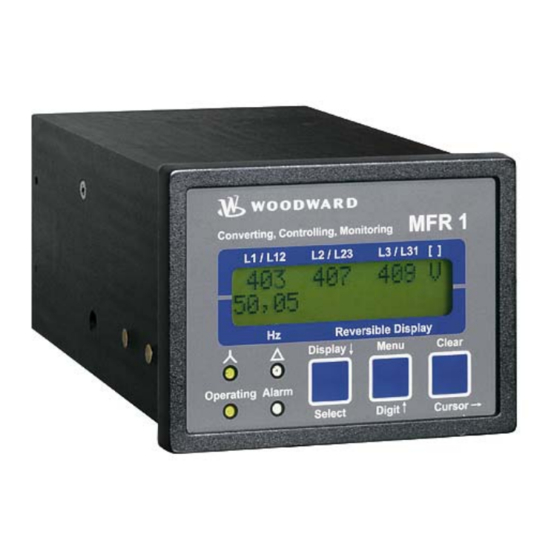
Page 24: Chapter 5. Display And Operating Elements
Manual 37140A MFR 11 - Protection Relay Chapter 5. Display and Operating Elements The pressure-sensitive membrane of the front panel consists of a plastic coating. All keys have been designed as touch-sensitive membrane switch elements. The display is a LC-display, consisting of 2 rows of 16 characters each, with indirect green lighting. -
Page 25: Leds
Manual 37140A MFR 11 - Protection Relay LEDs ≡≡≡≡≡≡≡≡≡≡≡≡≡≡≡≡≡≡≡≡≡≡≡≡≡ NOTE If neither of the "Wye" and "Delta" LEDs is illuminated, the first line of the display indicates the wire current values. "Wye" Indication of the wye voltages Color: Yellow If this LED is illuminated, the values indicated on the display are the wye (star) voltages (phase-neutral). -
Page 26: Push Buttons
Manual 37140A MFR 11 - Protection Relay Push Buttons ≡≡≡≡≡≡≡≡≡≡≡≡≡≡≡≡≡≡≡≡≡≡≡≡≡ In order to facilitate the setting of the parameters the buttons are equipped with an "AUTOSCROLL" function while the controller is in the configuration mode. It permits the user to rapidly advance to the next setting and configuration screens, the digits, or the cursor position. -
Page 27: Lc Display
Manual 37140A MFR 11 - Protection Relay LC Display ≡≡≡≡≡≡≡≡≡≡≡≡≡≡≡≡≡≡≡≡≡≡≡≡≡ LC Display LC display Performance values can be monitored from the two-line display, provided that the control is in automatic mode. In configuration mode, the individual parameters are displayed. Display in Automatic Mode (First Line of the Display: Measured Values) NOTE The user can scroll through the first display line with the button "Display ↓". -
Page 28: Display In Automatic Mode (Second Line Of The Display: Alarm Indication)
Manual 37140A MFR 11 - Protection Relay Display in Automatic Mode (Second Line of the Display: Alarm Indication) NOTE The user may scroll through the alarm messages that have occurred with the "Menu" button. Display in automatic mode, second line: Alarm indication ---------------- 00.00 yyyyyyyyyy... -
Page 29: Chapter 6. Configuration
Manual 37140A MFR 11 - Protection Relay Chapter 6. Configuration Configuration can be performed via the front panel push buttons and the front panel LC display or using a PC and the PC program LeoPC1 via the serial interface. If direct configuration via a PC is selected, the following baud rate is to be used: •... -
Page 30: Basic Data
Manual 37140A MFR 11 - Protection Relay Basic Data ≡≡≡≡≡≡≡≡≡≡≡≡≡≡≡≡≡≡≡≡≡≡≡≡≡ Software version Software version X.xxxx This screen displays the software version loaded into the control (the last two xx are for software revisions which do not affect the function of the unit). - Page 31 Manual 37140A MFR 11 - Protection Relay Breaking the seal number XXX YES/NO Code no. 000 Break? By entering "YES", you can break the seal and release the input mode. However, the sealing number is then increased by 1. Thus, it is possible at any time to check whether modifications have been made without the correct code number having been entered.
-
Page 32: Password (Starting With Version 2.0Xx / 3.0Xx)
Manual 37140A MFR 11 - Protection Relay Password (Starting with Version 2.0xx / 3.0xx) The unit is equipped with a three-level code and configuration hierarchy, which allows different user access to the control. A distinction is made between: Code level CS0 (User Level) Factory password = none This code level allows for monitoring of the system and does not permit access to the parameters. -
Page 33: Change Passwords (Starting With Version 2.0Xx / 3.0Xx)
Manual 37140A MFR 11 - Protection Relay Change Passwords (Starting with Version 2.0xx / 3.0xx) NOTE Once the code level is set, it will not be changed even after entering the configuration repeatedly an in- correct code number has been entered, the code level is set to CS0, thus locking the device for external persons. -
Page 34: Direct Configuration (From Version 3.0Xx)
• You may start the PC program as follows: - by "Start/Program/Woodward/LeoPC" (starting at version 3.1.xxx), or - by a double click on a file ending ".cfg" in the subdirectory "LeoPC". • After the PC program has been started, establish the communication by pressing the "F2" button. This will es- tablish a data link between the unit and the laptop/PC. -
Page 35: Measurement
Manual 37140A MFR 11 - Protection Relay Measurement ≡≡≡≡≡≡≡≡≡≡≡≡≡≡≡≡≡≡≡≡≡≡≡≡≡ WARNING The following values must be entered correctly for the generator to be monitored. Failure to do so may lead to incorrect measuring of parameters resulting in damage to or destruction of the generator or switchgear and/or personal injury or death. -
Page 36: Rated Voltage / Rated Frequency (Option Yc)
Manual 37140A MFR 11 - Protection Relay Units with Option YC Generator potential transformer secondary [1] 50 to 125 V; [4] 50 to 480 V Volt.transformer sec.(GN) 000V The potential transformer secondary voltage is set here in V. This parameter is util- ized to calculate the system voltage in the display. -
Page 37: Control Functions
Manual 37140A MFR 11 - Protection Relay Control Functions ≡≡≡≡≡≡≡≡≡≡≡≡≡≡≡≡≡≡≡≡≡≡≡≡≡ Synchronization (Option NOTE This Option YC is not available for 690 V units; refer to Synchronizing Voltage (Option on page 15. Output of the Signal "Systems are Synchronous" After the control unit monitors voltages and frequencies are within permissible limits, it will issue a circuit breaker closure command to connect two systems. - Page 38 Manual 37140A MFR 11 - Protection Relay Configuration Screens Synchronizing functions ON/OFF Synchronizing functions ON ....Synchronizing functions have been enabled, and the subsequent screens of this function are displayed. OFF ....Synchronizing functions have been disabled, and the subsequent screens of this function are not displayed.
-
Page 39: Type Of Monitoring
Manual 37140A MFR 11 - Protection Relay Type of Monitoring ≡≡≡≡≡≡≡≡≡≡≡≡≡≡≡≡≡≡≡≡≡≡≡≡≡ NOTE The following screen will not be displayed, if the parameter "Volt.-Measuring" is configured to "Phase to phase" power measurement (refer to Voltage Measurement on page 35). Monitoring for Phase-neutral/Phase to phase Volt. -
Page 40: Protection
Manual 37140A MFR 11 - Protection Relay Protection ≡≡≡≡≡≡≡≡≡≡≡≡≡≡≡≡≡≡≡≡≡≡≡≡≡ Overvoltage Monitoring (Option Function: "Voltage not within permissible limits" The monitored voltage in at least one phase is not within the configured permissible limits for overvoltage. The alarm message "Overvolt.1" or "Overvolt.2" will be displayed. This message cannot be suppressed with the discrete input "Blocking of protective functions / remote acknowledgement". -
Page 41: Undervoltage Monitoring (Option U)
Manual 37140A MFR 11 - Protection Relay Undervoltage Monitoring (Option Function: "Voltage not within permissible limits" The monitored voltage in at least one phase is not within the configured permissible limits for undervoltage. The alarm message "Und.volt.1" or "Und.volt.2" will be displayed. This message cannot be suppressed with the discrete input "Blocking of protective functions / remote acknowledgement". -
Page 42: Zero Voltage Monitoring (Option Un)
Manual 37140A MFR 11 - Protection Relay Zero Voltage Monitoring (Option Function: "Voltage within permissible limits" All three phases of the measured voltages are below the configured limit for a zero voltage condition. This func- tion may be used for dead bus detection and as a release signal to permit dead bus closure of the circuit breaker. -
Page 43: Voltage Asymmetry Monitoring (Option U)
Manual 37140A MFR 11 - Protection Relay Voltage Asymmetry Monitoring (Option The phase-phase voltages are monitored. Function "Voltage asymmetry not within permissible limits" The monitored phase-phase voltage differential in the three phases is not within the configured permissible limits for asymmetry (asymmetric voltage vectors; the threshold corresponding to the differential value). The alarm message "Asymmetry"... -
Page 44: Overfrequency Monitoring (Option U)
Manual 37140A MFR 11 - Protection Relay Overfrequency Monitoring (Option The monitoring of the frequency is carried out on two levels. The frequency measuring is monitored three-phase if all voltages are greater than 15 % of the rated value (100 V or 400 V). This ensures quick and precise meas- urement of the frequency. -
Page 45: Underfrequency Monitoring (Option U)
Manual 37140A MFR 11 - Protection Relay Underfrequency Monitoring (Option The monitoring of the frequency is carried out on two levels. The frequency measuring is monitored three-phase if all voltages are greater than 15 % of the rated value (100 V or 400 V). This ensures quick and precise meas- urement of the frequency. -
Page 46: Vector / Phase Shift Monitoring (Option V)
Manual 37140A MFR 11 - Protection Relay Vector / Phase Shift Monitoring (Option A vector/phase shift is defined as the sudden variation of the voltage curve which may be caused by a major gen- erator load change. The control unit measuring circuit detects the change in the cycle duration. This change in the cycle duration is compared with a mean value calculated from previous measurements. -
Page 47: Df/Dt (Rocof) Monitoring (Option D)
Manual 37140A MFR 11 - Protection Relay df/dt (ROCOF) Monitoring (Option Function: "Rate Of Change Of Frequency (ROCOF) is not within permissible limits" Rate of Change Of Frequency (ROCOF) monitoring measures the stability of the frequency. The frequency of a generator will vary due to changing loads and compensation of the fuel system. -
Page 48: Relay Configuration
Manual 37140A MFR 11 - Protection Relay Relay Configuration ≡≡≡≡≡≡≡≡≡≡≡≡≡≡≡≡≡≡≡≡≡≡≡≡≡ NOTE Clearing of faults and fault messages from the control unit will depend on the parameters "Exter- nal clearing", "Auto-clearing Relays", and "Auto-clearing Display". These three parameters will influence the other depending on how each is configured. This is explained in the following text. -
Page 49: Auto Acknowledgement Of Messages
Manual 37140A MFR 11 - Protection Relay NOTE The subsequent screens are only visible if the parameter "Auto-clearing Relays" and the corre- sponding protective function are enabled and the control unit is equipped with the protective function- ality. Release delay of the relays 0.02 to 99.98 s... -
Page 50: Changing The Relay Assignment (Relay Manager; Standard / Option R)
Manual 37140A MFR 11 - Protection Relay Changing the Relay Assignment (Relay Manager; Standard / Option Change relay assignment? YES/NO Change relay- allocation? This parameter permits the user to change how the relay outputs are configured. Refer to the list of parameters. -
Page 51: Table 6-2: Protective Function Output To Relay
Manual 37140A MFR 11 - Protection Relay NOTE The following screen(s) will only be displayed if the unit is equipped with the corresponding protective function(s), the protective function is enabled, and the parameter "Change relay allocation" is en- abled. Assign protective function output to relays... -
Page 52: Analog Outputs (Options A1/2/3/4/6/8)
Manual 37140A MFR 11 - Protection Relay Analog Outputs (Options A1/2/3/4/6/8) ≡≡≡≡≡≡≡≡≡≡≡≡≡≡≡≡≡≡≡≡≡≡≡≡≡ NOTE The common use of the analog outputs, the interfaces and the discrete inputs depends on their re- spective combinations. Please pay attention to the combinations possible as described in the intro- duction. - Page 53 Manual 37140A MFR 11 - Protection Relay Example: analog output 2 (-10/0 to 10 V: terminals 50/52, -20/0/4 to 20 mA: terminals 52/53) Output of the phase-to-phase voltage V L1-L2 Output range of the (20 mA) –20..+20 / 0..20 / 4..20 mA / OFF...
-
Page 54: Interface (Options Su/Sb)
Manual 37140A MFR 11 - Protection Relay Interface (Options SU/SB) ≡≡≡≡≡≡≡≡≡≡≡≡≡≡≡≡≡≡≡≡≡≡≡≡≡ CAUTION The communications bus interface functionality is disabled when the direct configuration port is en- abled. The parameter "Direct parametr." must be configured "NO" to re-enable the communication bus interface (refer to "Direct Configuration (from Version 3.0xx)"... -
Page 55: Screens For Protocol Can Bus (Options Su/Sb)
Manual 37140A MFR 11 - Protection Relay Screens for Protocol CAN Bus (Options SU/SB) NOTE Please note that IDs must not be allocated twice. This applies to all units linked to the bus system. Moreover, all IDs adjusted at the unit must be set to different values. -
Page 56: General Screens For All Interfaces (Option Sb)
Manual 37140A MFR 11 - Protection Relay General Screens for All Interfaces (Option Control via interface ON/OFF Serial control ON ....Control via the serial interface is enabled and control orders received via the interface are processed. OFF ....Control via the serial interface is disabled and control orders received via the interface are ignored. -
Page 57: Chapter 7. Commissioning
Manual 37140A MFR 11 - Protection Relay Chapter 7. Commissioning DANGER - HIGH VOLTAGE When commissioning the control, please observe all safety rules that apply to the handling of live equipment. Ensure that you know how to provide first aid in the event of an uncontrolled release of en- ergy and that you know where the first aid kit and the nearest telephone are. - Page 58 Manual 37140A MFR 11 - Protection Relay Now, proceed as follows to change the code level: until version 1.9xx: Sealing function Coding Enter: "ON" select and confirm using the "Select" button Code input Code no. 000 Code? ????? Enter: Button "Select".
-
Page 59: Appendix A. Dimensions
Manual 37140A MFR 11 - Protection Relay Appendix A. Dimensions Front view Configuration plug Back view with connecting terminals Back plate mounting optionally Configuration plug Bottom view Option Configuration plug Option A6/A8 Configuration plug 2003-01-31 | MFR 1 Dimensions r1ww-0503-ab.skf Figure 7-1: Dimensions ©... -
Page 60: Appendix B. Technical Data
Manual 37140A MFR 11 - Protection Relay Appendix B. Technical Data Nameplate ------------------------------------------------------------------------------------------------------ Serial number (numerical) Date of production (YYMM) Serial number (Barcode) Item number Item revision number Details Technical data Type Description (long) Type Description (short) UL sign Measuring voltage ---------------------------------------------------------------------------------------------... - Page 61 Manual 37140A MFR 11 - Protection Relay Relay outputs ----------------------------------------------------------------------------------potential free - Contact material....................... AgCdO - General purpose (GP) (U Cont, relay output AC ........2.00 Aac@250 Vac DC ........2.00 Adc@24 Vdc 0.36 Adc@125 Vdc 0.18 Adc@250 Vdc - Pilot duty (PD) (U Cont, relay output AC ..............
-
Page 62: Appendix C. Measured Quantities And Accuracy
Manual 37140A MFR 11 - Protection Relay Appendix C. Measured Quantities and Accuracy Measuring value Display/range Accuracy Note Frequency 40.0 to .80.0 Hz 0.05 Hz Voltage 0 to 520 V/0 to 65 kV Accuracy depending on the configured transformer ratio Reference conditions: The data apply to the following reference conditions: •... -
Page 63: Appendix D. Interface Telegram
Manual 37140A MFR 11 - Protection Relay Appendix D. Interface Telegram Communication Interface Addresses ≡≡≡≡≡≡≡≡≡≡≡≡≡≡≡≡≡≡≡≡≡≡≡≡≡ Number Content (words) Unit Remark 3964 Modbus CAN bus Profibus Telegram header "302" Telegram type (02, 03) MUX=1 Voltage L12 (04, 05) MUX=1 Voltage L23... - Page 64 Manual 37140A MFR 11 - Protection Relay Number Content (words) Unit Remark 3964 Modbus CAN bus Profibus Internal alarms 2 Bit 15 = 1 \ (44, 45) MUX=8 Overfrequency level 1 Bit 14 = 0 / Bit 13 = 1 \...
-
Page 65: Description Of The Data Format
Manual 37140A MFR 11 - Protection Relay Number Content (words) Unit Remark 3964 Modbus CAN bus Profibus Internal alarms 5 Bit 15 = 1 \ (50, 51) MUX=9 Internal Bit 14 = 0 / Bit 13 = 1 \ Internal... -
Page 66: Framework Data For The Interfaces
Manual 37140A MFR 11 - Protection Relay Framework Data for the Interfaces ≡≡≡≡≡≡≡≡≡≡≡≡≡≡≡≡≡≡≡≡≡≡≡≡≡ Framework Data to Procedure 3964 (TTY, RS-232, RS-485) String length ....... 8 bit Stop bit........ 1 bit Parity bit ......1 bit with even parity Idle state......This corresponds to the state log. "1" (20 mA with TTY) Data format ...... -
Page 67: Framework Data For Can Bus
Manual 37140A MFR 11 - Protection Relay Framework Data for CAN Bus Transmitting protocol..CAN (CiA) Hardware......CAN bus Transmission rate ....adjustable Special characteristic...Bt0 = 03, Bt1 = 1C Every 200 ms a data telegram of 8 bytes is sent, which is structured as follows (all word variables are in the high... -
Page 68: Framework Data For Profibus Dp
Manual 37140A MFR 11 - Protection Relay Framework Data for Profibus DP Receiving Range Byte 0 and the following ..Telegram according to description Example:......No. 1 - Byte 0/1 = telegram header "302" No. 2 - Byte 2/3 = voltage L12 No. -
Page 69: Appendix E. List Of Parameters
Manual 37140A MFR 11 - Protection Relay Appendix E. List of Parameters Product number P/N _____________________________ Rev _______________________________ Version MFR 11_______________________________________________________________ Project _____________________________________________________________________ Serial number S/N _______________ Date ______________________________ Setting range Parameter Default setting Customer setting tion 100/400/690 V BASIC DATA... - Page 70 Manual 37140A MFR 11 - Protection Relay Setting range Parameter Default setting Customer setting tion 100/400/690 V PROTECTION Overvoltage Monitoring ON/OFF Overvoltage 1 V(ph-ph)> 20 to 130 / 520 / 900 V 110/440/769 V V(Phase-N)> 10 to 75 / 300 V / 20 to 900 V...
- Page 71 Manual 37140A MFR 11 - Protection Relay Setting range Parameter Default setting Customer setting tion 100/400/690 V RELAY CONFIGURATION External Clearing ON/OFF Auto-clearing Relays ON/OFF Release delay Overvoltage 0.02 to 99.98 s 0.10 s Release delay Undervoltage 0.02 to 99.98 s 0.10 s...
- Page 72 Manual 37140A MFR 11 - Protection Relay Setting range Parameter Default setting Customer setting tion 100/400/690 V ANALOG OUTPUT CONFIGURATION A2/3/6 Analog output 1 A1/4/8 -20 to +20mA -/+20mA -/+20mA -20 to.+20mA 0 to 20 mA 0-20mA 0-20mA 4 to 20 mA...
- Page 73 Manual 37140A MFR 11 - Protection Relay Setting range Parameter Default setting Customer setting tion 100/400/690 V ANALOG OUTPUT CONFIGURATION A6/8 Analog output 6 -20 to +20mA -/+20mA -/+20mA -20 to.+20mA 0 to 20 mA 0-20mA 0-20mA 4 to 20 mA...
-
Page 74: Table 7-1: Analog Outputs, Table Of Values
Manual 37140A MFR 11 - Protection Relay Value Lower and upper setting value 0 V, -10 V 10 V, 20 mA 0 mA, 4 mA, -20 mA V L1-N 0 to 65,000 V V L2-N 0 to 65,000 V V L3-N... -
Page 75: Appendix F. Service Options
≡≡≡≡≡≡≡≡≡≡≡≡≡≡≡≡≡≡≡≡≡≡≡≡≡ If a control (or any part of an electronic control) is to be returned to Woodward for repair, please contact Wood- ward in advance to obtain a Return Authorization Number. When shipping the unit(s), attach a tag with the fol- lowing information: •... -
Page 76: Packing A Control
Stuttgart [+49 (711) 789 54-0]. They will help expedite the processing of your order through our distributors or local service facility. To expedite the repair process, contact Woodward in advance to obtain a Return Authoriza- tion Number, and arrange for issue of a purchase order for the unit(s) to be repaired. No work can be started until a purchase order is received. -
Page 77: How To Contact Woodward
+49 (711) 789 54-100 e-mail: stgt-info@woodward.com For assistance outside Germany, call one of the following international Woodward facilities to obtain the address and phone number of the facility nearest your location where you will be able to get information and service. Facility... -
Page 78: Engineering Services
MFR 11 - Protection Relay Engineering Services ≡≡≡≡≡≡≡≡≡≡≡≡≡≡≡≡≡≡≡≡≡≡≡≡≡ Woodward Industrial Controls Engineering Services offers the following after-sales support for Woodward prod- ucts. For these services, you can contact us by telephone, by e-mail, or through the Woodward website. • Technical support •... -
Page 79: Technical Assistance
Manual 37140A MFR 11 - Protection Relay Technical Assistance ≡≡≡≡≡≡≡≡≡≡≡≡≡≡≡≡≡≡≡≡≡≡≡≡≡ If you need to telephone for technical assistance, you will need to provide the following information. Please write it down here before phoning: Contact Your company ___________________________________________________ Your name ______________________________________________________... - Page 80 Phone +49 (711) 789 54-0 • Fax +49 (711) 789 54-100 stgt-info@woodward.com Homepage http://www.woodward.com/power Woodward has company-owned plants, subsidiaries, and branches, as well as authorized distributors and other authorized service and sales facilities throughout the world. Complete address/phone/fax/e-mail information for all locations is available on our website (www.woodward.com).
Need help?
Do you have a question about the MFR 11 and is the answer not in the manual?
Questions and answers