
Related Manuals for Woodward WIC1 Series


Summary of Contents for Woodward WIC1 Series
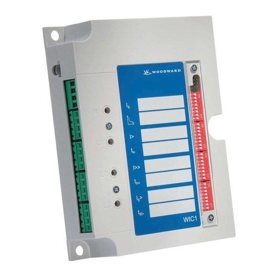
- Page 1 WIC1 – CT Powered Time Overcurrent And Earth Current Relay Manual WIC1 (Revision D)
- Page 2 Woodward Manual WIC1 GB Woodward Governor Company reserves the right to update any portion of this publication at any time. Information provided by Woodward Governor Company is believed to be correct and reliable. However, no responsibility is as- sumed by Woodward Governor Company unless otherwise expressly undertaken.
-
Page 3: Table Of Contents
Manual WIC1 GB Woodward Contents Comments on the manual ................5 Information Concerning Liability and Warranty ..............5 IMPORTANT DEFINITIONS ....................6 Electrostatic Discharge Awareness..................7 Introduction ....................8 How to use this instruction ....................8 ... - Page 4 Woodward Manual WIC1 GB Commissioning and Maintenance ............41 6.1.1 Important note ....................... 41 Accessories for commissioning work ................41 Criteria to be taken into account for protection devices fed by CT’s ......41 ...
-
Page 5: Comments On The Manual
(projecting) work, parameter setting or adjustment changes done by the customer. The warranty expires after a device has been opened by others than Woodward Kempen special- ists. Warranty and liability conditions stated in Woodward Kempen GmbH General Terms and Condi- tions are not supplemented by the above mentioned explanations. -
Page 6: Important Definitions
Woodward Manual WIC1 GB IMPORTANT DEFINITIONS The signal definitions shown below serve the safety of life and limb as well as for the appropriate operating life of the device. DANGER indicates a hazardous situation which, if not avoided, will result in death or serious injury. -
Page 7: Electrostatic Discharge Awareness
Guide for Handling and Protection of Electronic Controls, Printed Circuit Boards, and Modules. Woodward Kempen GmbH reserves the right to update any portion of this publication at any time. Information provided by Woodward Kempen GmbH is believed to be correct and relia- ble. -
Page 8: Introduction
Manual WIC1 GB 2. Introduction Woodward protection relays of the WI-LINE are offering time over current protective functions and earth fault protective functions in the well-proven technique for CT powered protection relays. As combination of a compact protection relay and related core-type transformer, the WIC1 system was especially developed for compact MV switchboards with circuit breakers. -
Page 9: Product Description
Manual WIC1 GB Woodward Product description The WIC1 is a CT-powered protection relay with inverse time and definite time protection charac- teristics and is specifically designed for switchboards with CBs and small rated output currents. Together the specific CTs and the WIC1 form a joint protective system. A low-energy coil is needed for realising trip of the CB. -
Page 10: Handling, Installation And Outside Dimensions
Woodward Manual WIC1 GB 3. Handling, Installation and Outside Dimensions General information 3.1.1 Upkeep of the relay As a rule protection relays are of robust construction and the WIC1 in particular allows operation under extreme environmental conditions. But despite these facts, the WIC1 should be handled with the necessary care during installation and commissioning. -
Page 11: Outside Dimensions
Manual WIC1 GB Woodward Outside dimensions All WIC1 types are of standardized design. Weight: 700g Dimensions: (Width x Height x Depth) 125x170x40mm Connection Diagram gn/ge gn/ge gn/ge Schauzeichen Flag indicator Energiearme / low energy Auslösespule / tripping 230V Eingang Fernauslöser... -
Page 12: Operating Instructions
Woodward Manual WIC1 GB 4. Operating instructions General information on the WIC1 All available versions of the WIC1 relay are a high-tech and cost-optimized protection for MV switchboards. Specifically in compact switchboards, the WIC1 protection system in combination with a circuit breaker can replace the combination of load-break-switch with HV fuses. Thereby in particular the overload protection for the attached unit is improved clearly. -
Page 13: User Interface
Manual WIC1 GB Woodward User interface 4.2.1 WIC1-1/WIC1-4 Pursuant to the intended maintenance-free design and for reducing cost there is no user interface with LED indicators and display. The setting values of the protective functions can be recorded di- rectly at the protection relay. -
Page 14: Wic1-2
Woodward Manual WIC1 GB When compared to WIC1-1, the WIC1-4 provides an additional operator interface at its front panel. Position and function are the same as for all other unit versions. Figure 4.2: WIC1-4 Note! For the operating software “WIC-Soft1” a separate description is available. - Page 15 Manual WIC1 GB Woodward The interface for this version can be found at the left of the relay and additionally above the DIP switch block. Switch block; Switch No. Setting parameter 1; 1-4 : Rated CT current 1; 5-8 Choice of characteristics 2;...
-
Page 16: Wic1-3
Woodward Manual WIC1 GB 4.2.3 WIC1-3 For the relay version WIC1-3 the adjustment of protective functions can be done via HEX switches at the protection relay. Because there are only 16 steps available for setting the individual protective parameters, scaling is more coarse than this is the case with parameter setting via software. -
Page 17: Cts For The Wic1
Manual WIC1 GB Woodward CTs for the WIC1 There are five different wide-range CTs for the protection system WIC1. Dependent on the rated primary power and voltage of the system, the following CTs can be offered: CT Type Rated CT current IS WIC1-WE1 8 –... -
Page 18: Technical Data, Characteristics And Features
Woodward Manual WIC1 GB 5. Technical Data, Characteristics and Features Protective functions 5.1.1 Minimal operating current and rated primary current In order to operate reliably, the WIC1 – as all CT-powered protection relays – needs a minimal cur- rent flowing constantly in one of the phases. This minimal current is the smallest rated CT current (IS) x 0.9 listed in table. -
Page 19: Phase Time Over Current Protection
Manual WIC1 GB Woodward 5.1.2 Phase time over current protection The following setting ranges and gradings apply for the WIC1-1. Here the parameters can only be set via a serial interface. Current Arithmetic averages measurement Threshold values I> 0.9 to 2.5 x IS in steps of 0.05 x I when adjusting via interface I>>... - Page 20 Woodward Manual WIC1 GB For relay versions WIC1-2 and WIC1-3 the adjustment of values is done according to the tables listed below: Characteristic curve = HEX-Switch 2/DIP-Switch 1 (5 - 6) OFF ON OFF ON OFF ON OFF ON DIP 1-5...
-
Page 21: Earth Current Protection
Manual WIC1 GB Woodward 5.1.3 Earth current protection Current Internal calculated cumulative current formation 0.2 to 2.5 x IS in steps of 0.05 x IS E> when adjusting via the interface for the WIC1-1 Tripping time 0.1s to 20s in steps of 0.01 when adjusting via IE>... -
Page 22: Routine Safety Check
Woodward Manual WIC1 GB Routine safety check In case of misadjustment of the relay, e.g. selection of non-assigned switch positions, the relay op- erates with the following setting values. = upper rated CT current Characteristic = DEFT I> Deactivated (Exit) 0.04 s... -
Page 23: Communication
For connection to the USB interface of a PC a WIC1-PC3 adapter is needed. Through these adapters the galvanic isolation between protection device and the PC is reached and it supplies the WIC1 with the necessary energy. For communication a proprietary Woodward protocol is used. -
Page 24: Inputs And Outputs
Woodward Manual WIC1 GB Inputs and outputs The terminals for connection of the CT, the tripping coil of the external trip input as well as the flag indicator output are provided at the left side of the WIC1. Dependent on the relay type either screw- type terminals or screw-type plug-in terminals in 4-block arrangement are used. -
Page 25: Measuring Inputs For The Cts
Manual WIC1 GB Woodward 5.6.5 Measuring inputs for the CTs The measuring inputs of the WIC1 protection system are matching the allocated CTs. Also the power requirement of the relay and the CT output power match. The connection of common CTs with secondary currants of 1 A or 5 A is inadmissible! -
Page 26: Technical Data
Woodward Manual WIC1 GB Technical Data 5.7.1 Common Data Frequency: 45 Hz to 65 Hz Nominal: 50/60 Hz Thermal load capacity: Permanently: 2.5 x highest rated CT current 25 kA CT primary current 20 kA CT primary current Dynamic load capacity: 62.5 kA CT primary current... -
Page 27: Insulation Voltage Withstand
Manual WIC1 GB Woodward 5.7.4 Insulation voltage withstand Test of withstand alternating voltage for 1 min: IEC 60255-5 2.5 kV Test of lightning surge voltage 1.2/50 µs, 0.5 J IEC 60255-5 5 kV 5.7.5 EMC Interference immunity against discharges of static electricity... -
Page 28: Ambient Conditions
Woodward Manual WIC1 GB 5.7.6 Ambient conditions Vibration and continuous vibration test DIN EN 60255-21-1 [05/96] 1/2 gn Class 2 Shock and continuous shock test DIN EN 60255-21-2 [05/96] 10/20 gn Class 2 Earthquake test DIN EN 60255-21-3 [11/95] 2 gn... -
Page 29: Outside Dimension Of Cts
Manual WIC1 GB Woodward 5.7.7 Outside dimension of CTs The structural forms of the CTs depend on the switchboard construction, i.e. they are in compliance with specific customer needs. We have various standard designs. For further information please contact your sales partner. - Page 30 Woodward Manual WIC1 GB Type: WIC1-W6AS1 Figure 5.4: Type WIC1-W6AS1 as panel mounting Figure 5.5: Type WIC1-WxH1 as plug on type DOK-TD-WIC1 Rev.C...
-
Page 31: Characteristics And Times
Manual WIC1 GB Woodward Characteristics and times 5.8.1 Characteristic curves 1000 10.0 t[s] 0.05 5 6 7 8 910 Multiples of pick up setting * Figure 5.5: Normal Inverse *Multiples of pick up setting = Is * I> 1000 t[s] 10.0... - Page 32 Woodward Manual WIC1 GB 10000 1000 t[s] 10.0 0.05 0.05 0.01 5 6 7 8 910 Multiples of pick up setting * Figure 55.7: Extremely Inverse *Multiples of pick up setting = Is * I> I> I> I> I> t[s] >...
- Page 33 Manual WIC1 GB Woodward 10000 1000 t[s] 10.0 0.05 0.05 5 6 7 8 910 Multiples of pick up setting * Figure 5.9: Long time inverse *Multiples of pick up setting = Is * I> 10000 1000 t[s] 10.0 0.01...
- Page 34 Woodward Manual WIC1 GB 10.0 t[s] 0.05 5 6 7 8 910 Multiples of pick up setting * Figure 5.2: RI-Inverse *Multiples of pick up setting = 100000 10000 1000 t[s] 10.0 0.01 5 6 7 8 910 Multiples of pick up setting * Figure 5.3: FR-fuse...
-
Page 35: Calculation Formula For Imt Characteristics
Manual WIC1 GB Woodward 5.8.2 Calculation formula for IMT characteristics Normal Inverse: 0.14 · Very Inverse: 13.5 · Extremely Inverse: · Long time inverse: · RI-Inverse Time: · 0.236 0.339 HV-Fuse: · · · FR-Fuse · · · 2.66 ·... -
Page 36: Flag Indicators
Woodward Manual WIC1 GB 5.8.3 Flag Indicators WI1-SZ4 Technical Data Coil: 24V DC 10% - can be set electrically - can be reset mechanically Connector assignment Coil connection Core color mm² Function black 0.25 Gnd/Set black 0.25 Gnd/Set Cable connection length:... -
Page 37: Description Of Application
Manual WIC1 GB Woodward Description of application 5.10 Foreword As CT-powered protection relay the WIC1 is mainly used in MV switchboards with circuit breakers, protecting distribution transformers in local and industrial networks. Due to its small size the WIC1 is very well suited for the use in compact switchboards. -
Page 38: Selection Of The Ct Transformation Voltage Ratio
Woodward Manual WIC1 GB 5.11 Selection of the CT transformation voltage ratio Selection of the CT suitable for the WIC1 depends on the rated current of the transformer to be protected and is calculated acc. to the following formula: Example:... -
Page 39: Adjustment Instruction For Inverse Characteristic
Manual WIC1 GB Woodward 5.12 Adjustment instruction for inverse characteristic In the introduction phase of the WIC1 it came to understanding problems during the adjustment of the protection relay, in particular when using inverse characteristics. In the following now the con- nections are for this described. - Page 40 Woodward Manual WIC1 GB Estimation of the tripping time at inverse characteristics The setting and estimation by the use of an inverse characteristic will be explained at the following example. Boundary condition: Operating current of the load (IS) Selected CT ratio WIC1-W3, 32 A –...
-
Page 41: Commissioning And Maintenance
Manual WIC1 GB Woodward 6. Commissioning and Maintenance 6.1.1 Important note Putting into operation and the relevant tests should only be carried out by skilled personnel. We do not accept any liability for damage caused by im- proper handling of the protection system, or of the primary side of the equipment. -
Page 42: Special Features For The Wic1 Test
Woodward Manual WIC1 GB Lowest operating current = lower rated current x 0,9. The operating current is choosen by Is * I>. WIC1-W1xx: 7.2 A (Is = 8 A) WIC1-W2xx: 14.4 A (Is = 16 A) WIC1-W3xx: 28.8 A (Is = 32 A) WIC1-W4xx: 57.6 A (Is = 64 A) -
Page 43: Wic1 Adjustment
Manual WIC1 GB Woodward The testing current is fed via sockets L1, L2, L3 and N. The test winding is rated such that the fed current of 1A balances a primary current of 50A (CT type WIC1-W2). The timer should be connect parallel to the tripping coil or the flag indicator. -
Page 44: Test Currents
Woodward Manual WIC1 GB 6.7.1 Test Currents The transformation ratio of primary currents to secondary currents of the CTs are equally propor- tionate as the test current via the CD winding to the secondary current. This means, no matter which CT type is in operation, for the secondary test always the same test values are used. -
Page 45: Switching Points For The Short-Circuit Step
Manual WIC1 GB Woodward 6.7.3 Switching points for the short-circuit step DIP 1-1 DIP 1-2 OFF OFF OFF OFF OFF OFF OFF OFF DIP 1-3 OFF OFF OFF OFF OFF OFF OFF OFF DIP 1-4 OFF OFF OFF OFF OFF OFF OFF OFF HEX-Schalter I>>... -
Page 46: Special Features For Earth Current Tests
Woodward Manual WIC1 GB Special features for earth current tests Functional description: In the WIC1 the earth current is calculated and cannot be measured. It is established from the ge- ometrical amount of the three phase current values, more or less a numerical Holmgreen. If, for in- stant, a single-phase test current is impressed, the measuring value (tripping value) in the earth current path equals the current in the tested phase. -
Page 47: Test Procedure By Way Of Example
Manual WIC1 GB Woodward Test procedure by way of example When testing the WIC1, the tests of the individual equipment should be carried out from the highest setting value to the smallest one. The order ought to be: 1) short circuit I>>... - Page 48 Woodward Manual WIC1 GB Test step 3): Test of the over-current step I>: Settings: I> = 1.05 x Is tI> = EXIT I>> = 4.00 x Is tI>> = 0.10s IE> = EXIT tIE> = 0.2s Test to be carried out as described under “Test step 1”.
-
Page 49: Maintenance
Manual WIC1 GB Woodward 6.10 Maintenance The entire protection system WIC1 is designed for a maintenance-free period of 25 years, hence there are no specific jobs necessary to be done during the operating life of the relays. Very often, a periodical check of the protective adjustments is required by the end user. -
Page 50: Product Specific Features
Woodward Manual WIC1 GB 7. Product Specific Features Assignment of terminals The protection relay is equipped with 20 screw-type terminals, make Phoenix and 4 test sockets. The 2 different relay versions are defined by the kind of terminal used: WIC1-xP... -
Page 51: Current Transformer
Manual WIC1 GB Woodward Current transformer Listed CT ranges in relation to the transformer rated currents 3.00 3.30 4.20 5.50 6.00 6.60 10.00 11.00 12.00 13.80 15.00 15.50 17.50 20.00 21.00 22.00 24.00 U[kV] 50.00 9,62 8,75 WIC1-W1 75.00 14,43... -
Page 52: Annex
Woodward Manual WIC1 GB 8. Annex Dimensional drawing relay Figure 8.1: Dimensional drawing Dimensional drawing flag indicator Figure 88.2: Flag indicator WI1-SZ4/WI1-SZ5 DOK-TD-WIC1 Rev.C... -
Page 53: Order Form
Manual WIC1 GB Woodward Order form Multi characteristic time over current relay WIC1 3-phase current measuring I>;I>> self powered – parameter setting via serial interface – parameter setting via DIP switches – parameter setting via HEX switches – Parameter setting via interface, with LED and second operator interface Connection mode –... -
Page 54: Commissioning Form
Woodward Manual WIC1 GB Commissioning form List of adjustments for WIC1 Project: Order No.: Functional group: Location: Component Identification: Relay Function: Date: Parameter Setting Default Actual Function Unit Setting Setting CT Type Rated CT current Char Trip characteristic DEFT I>... - Page 55 Manual WIC1 GB Woodward DOK-TD-WIC1 Rev.C...
- Page 56 Woodward Manual WIC1 GB Woodward Kempen GmbH Krefelder Weg 47 D – 47906 Kempen (Germany) Postfach 10 07 55 (P.O.Box) D – 47884 Kempen (Germany) Phone: +49 (0) 21 52 145 1 Internet www.woodward.com Sales Phone: +49 (0) 21 52 145 216 or 342 Telefax: +49 (0) 21 52 145 354 e-mail: salesEMEA_PGD@woodward.com...
Need help?
Do you have a question about the WIC1 Series and is the answer not in the manual?
Questions and answers