Table of Contents
Advertisement
Advertisement
Table of Contents

Subscribe to Our Youtube Channel
Summary of Contents for Woodward XR1
- Page 1 XR1 – Rotor Earth Fault Relay Manual XR1 (Revision A)
- Page 2 Woodward Manual XR1 GB Woodward Governor Company reserves the right to update any portion of this publication at any time. Information provided by Woodward Governor Company is believed to be correct and reliable. However, no responsibility is as- sumed by Woodward Governor Company unless otherwise expressly undertaken.
-
Page 3: Table Of Contents
Manual XR1 GB Woodward Content Applications and features ................4 Design ......................5 Function ......................6 Operation and settings ................8 Setting of DIP-switches ....................... 9 Setting of the tripping values ..................... 10 ... -
Page 4: Applications And Features
Manual XR1 GB 1. Applications and features Protection relay XR1 of our PROFESSIONAL LINE is used for detection of rotor earth faults in syn- chronous machines. The earth fault element detects high and low impedance earth faults in rotor windings and is in two stage design (for alarm and trip). -
Page 5: Design
Unit XR1 needs a separate auxiliary voltage supply. Therefore a dc or ac voltage must be used. Unit XR1 has an integrated wide range power supply. Voltages in the range from 19 - 390 Vdc or 36 - 275 Vac can be applied at connection terminals A1 and A2. -
Page 6: Function
XR1 provides an alarm and a trip element for the rotor earth fault protection. The insulation resistance measurement system of the XR1 can be used for synchronous genera- tors of both types, with and without brushes. - Page 7 Manual XR1 GB Woodward Figure 3.2 explains the measuring principle: Figure 3.2: Measuring principle DOK-TD-XR1 Rev.A...
-
Page 8: Operation And Settings
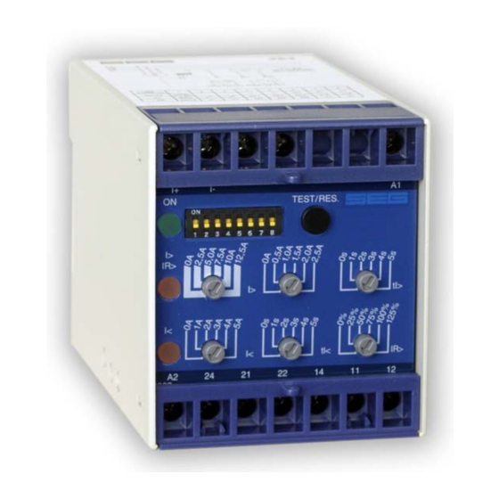
Manual XR1 GB 4. Operation and settings All operating elements needed for setting parameters are located on the front plate of the XR1 as well as all display elements. Because of this all adjustments of the unit can be made or changed without disconnecting the unit off the DIN-rail. -
Page 9: Setting Of Dip-Switches
Manual XR1 GB Woodward Setting of DIP-switches The DIP-switch block on the front plate of the XR1 is used for adjustment of the nominal values and setting of function parameters: DIP-switch Function active blocked Rotor earth fault warning active blocked Rotor earth fault tripping Multiplier for tR<... -
Page 10: Setting Of The Tripping Values
Woodward Manual XR1 GB Setting of the tripping values The PROFESSIONAL LINE units have the unique possibility of high accuracy fine adjustments. For this, two potentiometers are used. The coarse setting potentiometer can be set in discrete steps of 20 kΩ or 5 kΩ. A second fine adjustment potentiometer is then used for continuously variable set- ting of the final (0 - 20 kΩ... -
Page 11: Communication Via Serial Interface Adapter Xrs1
Manual XR1 GB Woodward Communication via serial interface adapter XRS1 Figure 4.5: Communication principle For communication of the units among each other and with a superior management system, the in- terface adapter XRS1 is available for data transmission, including operating software for our relays. -
Page 12: Relay Case And Technical Data
5. Relay case and technical data Relay case Relay XR1 is designed to be fastened onto a DIN-rail acc. to DIN EN 50022, the same as all units of the PROFESSIONAL LINE. The front plate of the relay is protected with a sealable transparent cover (IP40). -
Page 13: Technical Data
Manual XR1 GB Woodward Technical data Measuring input circuits Thermal withstand capability in measuring circuit: during 10 s Umax = 600 V continuous Umax = 140 VAC/DC Output voltage of measuring circuit: = ±24 V (short circuit proof) = 1 Hz... - Page 14 Woodward Manual XR1 GB Radiated electromagnetic field test acc. to IEC 0801, part 3: 10 V/m Electrical fast transient (burst) acc. to IEC 0801, part 4: 4 kV/2.5kHz, 15 ms Radio interference suppression test as per DIN 57871 and VDE 0871:...
- Page 15 Manual XR1 GB Woodward Setting-list XR1 Project: Woodward job.-no.: Function group: = Location: + Relay code: - Relay functions: Date: Setting of parameters Function Unit Default settings Actual settings R< Rotor earth fault alarm kΩ R<< Rotor earth fault tripping kΩ...
- Page 16 Woodward Manual XR1 GB Woodward Kempen GmbH Krefelder Weg 47 D – 47906 Kempen (Germany) Postfach 10 07 55 (P.O.Box) D – 47884 Kempen (Germany) Phone: +49 (0) 21 52 145 1 Internet www.woodward.com Sales Phone: +49 (0) 21 52 145 216 or 342 Telefax: +49 (0) 21 52 145 354 e-mail: salesEMEA_PGD@woodward.com...


Need help?
Do you have a question about the XR1 and is the answer not in the manual?
Questions and answers