Table of Contents
Advertisement
Quick Links
Advertisement
Table of Contents

Related Manuals for Woodward MFR 13 Series


Summary of Contents for Woodward MFR 13 Series
- Page 1 37353A MFR 13 Packages Protection Relay Manual Version 3.1xxx Manual 37353A...
- Page 2 Provides other helpful information that does not fall under the warning or caution categories. Woodward reserves the right to update any portion of this publication at any time. Information provided by Woodward is believed to be correct and reliable. However, Woodward assumes no responsibility unless otherwise expressly undertaken.
-
Page 3: Table Of Contents
LC Display.............................29 Display in Automatic Mode (First Line of the Display: Measured Values)........29 Display in Automatic Mode (Second Line of the Display: Measured Values) ......29 Display in Automatic Mode (Second Line of the Display: Alarm Indication).......30 © Woodward Page 3/91... - Page 4 Description of the Data Format......................78 Examples............................ 79 Bit Change at Tripping of a Watchdog Function ................ 79 Framework Data for the Interfaces....................... 79 Framework Data for Modbus RTU Slave ................... 79 E. L ..................80 PPENDIX IST OF ARAMETERS Page 4/91 © Woodward...
- Page 5 F. S ....................86 PPENDIX ERVICE PTIONS Product Service Options ........................86 Returning Equipment for Repair ......................86 Packing a Control ........................87 Return Authorization Number RAN ....................87 Replacement Parts..........................87 How to Contact Woodward ........................88 Engineering Services ..........................89 Technical Assistance ..........................90 © Woodward Page 5/91...
- Page 6 Table 6-1: Release delay of the relays ............................. 60 Table 6-2: Protective function output to relay ......................... 62 Table 6-3: Analog outputs, table of values ..........................64 Table 7-1: Analog outputs, table of values ..........................85 Page 6/91 © Woodward...
-
Page 7: Chapter 1. General Information
(flush mounted, standard unit with 100 Vac PT and ../5 A CT inputs with 8 configurable relays, 3 analog outputs, pulse output, true RMS busbar voltage measuring synch-check func- tion, RS-485 Modbus RTU Slave interface, and wide-range power supply) © Woodward Page 7/91... -
Page 8: Measurement Value Logging
0.1 kWh. The unit automatically increases the engineering unit of measure when the maximum value has been reached. This permits a measuring range up to 4,290 GWh. This counter is not Physikalisch-Technische Bundesanstalt (PTB) calibrated. Page 8/91 © Woodward... -
Page 9: Package Functional Descriptions
The manual is therefore only a guide. In case of incorrect entries or a total loss of functions, the default settings may be taken from the list of parameters enclosed at the rear of this manual. © Woodward Page 9/91... -
Page 10: Chapter 2. Electrostatic Discharge Awareness
CAUTION To prevent damage to electronic components caused by improper handling, read and observe the pre- cautions in Woodward manual 82715, Guide for Handling and Protection of Electronic Controls, Printed Circuit Boards, and Modules. Page 10/91 © Woodward... -
Page 11: Chapter 3. Installation
90 to 265 Vac/dc E = Package GPY-I-N 0 Vdc C (kWh impulse) Blocking of watchdog functions/ remote acknowledgement E (open collector) Subject to technical modifications. 2006-02-16 | MFR 13 Wiring Diagram r13ww-0706-ap.skf Figure 3-1: Wiring diagram © Woodward Page 11/91... -
Page 12: Power Supply (Packages Gpx / Gpxx / Gpxx-I / Gpxy-I / K08)
Wide-range power supply + / L Power supply - / N Figure 3-3: Wide range power supply Terminal Description Wide range power supply unit (Package GPY-I-N) 90 to 265 Vac/dc 2.5 mm² 0 V reference point 2.5 mm² Page 12/91 © Woodward... -
Page 13: Measuring Inputs
Synchronizing voltage Figure 3-5: Measuring inputs - synchronizing voltage Terminal Measurement Description 400V direct Synchronizing voltage L1 2.5 mm² or via transf. Synchronizing voltage L2 2.5 mm² ../100V Synchronizing voltage L3 (not measured) 2.5 mm² © Woodward Page 13/91... -
Page 14: Current
Generator current L2, transformer terminal s1 (k) 4 mm² ../1 A or Generator current L2, transformer terminal s2 (l) 4 mm² ../5 A Generator current L3, transformer terminal s1 (k) 4 mm² Generator current L3, transformer terminal s2 (l) 4 mm² Page 14/91 © Woodward... -
Page 15: Discrete Inputs
Discrete Inputs ≡≡≡≡≡≡≡≡≡≡≡≡≡≡≡≡≡≡≡≡≡≡≡≡≡ 18 to 250 Vac/dc Signal device Discrete input Figure 3-7: Discrete inputs Terminal Assigned Description common (according to DIN 40 719 Part 3, 5.8.3) Blocking of protective functions / remote acknowl- 2.5 mm² edgement © Woodward Page 15/91... -
Page 16: Outputs
Pkgs. GPX GPX-I GPY-I GPY-I-N 2.5 mm² Pulse Output (Packages GPY-I / GPY-I-N) 24 V DC R > 1 kOhm Pulse output Open collector Figure 3-9: Pulse output Terminal Description Pulse output (Open Collector) 2.5 mm² Page 16/91 © Woodward... -
Page 17: Analog Outputs (Packages Gpy-I / Gpy-I-N)
Description 0 to 20 / 4 to 20 -20 to +20 mA Analog output 1 Packages GPY-I GPY-I-N 1.5 mm² Analog output 2 Packages GPY-I GPY-I-N 1.5 mm² Analog output 3 Packages GPY-I GPY-I-N 1.5 mm² © Woodward Page 17/91... -
Page 18: Interface (Packages Gpx-I / Gpy-I / Gpy-I-N / K08)
RS-485, Modbus RTU Slave NOTE The Modbus interface connection may be performed at the terminals X1 through X3 or X3 through X5. The terminals X1 and X4 as well as X2 and X5 are connected internally. Page 18/91 © Woodward... -
Page 19: Dpc - Direct Configuration Interface
If the parameter "Direct config." is enabled on the control, communication via the CAN bus interface on terminals X1/X5 is disabled. If the control unit detects that the engine is running (ignition speed exceeded), the direct configuration port is disabled. © Woodward Page 19/91... -
Page 20: Chapter 4. Functional Description
"Clear" button resets the relays. ON....All alarm messages are reset if terminals 5/6 ("Blocking of protective functions / remote acknowledgement") are ener- gized. Alarms that cannot be blocked are only reset after the fault is no longer present. Page 20/91 © Woodward... -
Page 21: Control Outputs
The synch-check function is assigned to this relay. Relay 8 Terminal 31/32 NOTE For units with Packages GPX GPX-I GPY-I GPY-I-N / K08, the synch-check function is assigned to relay 8. Therefore, relay 8 cannot be configured with the relay manager. © Woodward Page 21/91... -
Page 22: Direction Of Power
The generator supplies active load. Inductive generator power factor The generator is overexcited and supplies Positive reactive power inductive reactive power. MAINS MFR 1 circuit breaker s2 (l) S2 (L) s1 (k) S1 (K) GENERATOR Figure 4-1: Direction of power Page 22/91 © Woodward... -
Page 23: Power Factor Definition
"more inductive" than the reference ured value is "more capacitive" than the reference set set point point Example: measured = i0.91; set point = i0.95 Example: measured = c0.91; set point = c0.95 © Woodward Page 23/91... - Page 24 Manual 37353A MFR 13 Packages - Protection Relay Phasor diagram: inductive capacitive Page 24/91 © Woodward...
-
Page 25: Alarms
If the parameter "Auto clearing displays" is configured "ON", the LED ex- tinguishes after the resetting time has expired. If the parameter "Auto clearing displays" is configured "OFF", the LED is extinguished only after pressing the "Clear" button. © Woodward Page 25/91... -
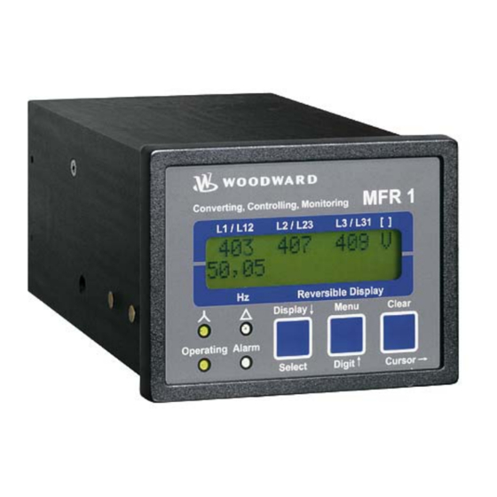
Page 26: Chapter 5. Display And Operating Elements
Menu Select menu Digit↑ Increase the digit Clear Acknowledgement of alarm messages Cursor→ Move cursor one position to the right Miscellaneous No. Description Function LC Display LC Display Potentiometer Adjust LCD contrast DPC plug Configuration plug Page 26/91 © Woodward... -
Page 27: Leds
This LED flashes as long as a set point limit is exceeded. When all measur- ing values are below the configured set point limit again and "Auto clearing display" is configured "OFF", this LED will change to steady illumination. © Woodward Page 27/91... -
Page 28: Push Buttons
Configuration: Cursor→ - This button moves the cursor one position to the right. When the cursor reaches the extreme right position it may be returned to the extreme left position by pressing the Cursor→ button again. Page 28/91 © Woodward... -
Page 29: Lc Display
Unit dynamic in [kWh / MWh] • Ground current Ie Unit static in [A] • Synchronizing voltage Unit dyn. in [V/kV]GPX/GPX-I/GPY-I/GPY-I-N/K08 • Synchronizing frequency Unit static in [Hz] GPX/GPX-I/GPY-I/GPY-I-N/K08 • Synchronizing angle Unit static in [°] GPX/GPX-I/GPY-I/GPY-I-N/K08 © Woodward Page 29/91... -
Page 30: Display In Automatic Mode (Second Line Of The Display: Alarm Indication)
Ground fault, calculated, level 1 Standard Earthcur.1 Ground fault, calculated, level 2 Standard Earthcur.2 Overload Standard Overload Reverse-/reduced power Standard Rev. power Unbalanced load Standard Unbalance Reactive power, capacitive Standard React.pow- Reactive power, inductive Standard React.pow+ Table 5-1: Alarm messages Page 30/91 © Woodward... -
Page 31: Chapter 6. Configuration
If a parameter is con- figured "OFF", the related screens are not displayed or monitored by the control. Pressing the "Select" button will advance the displayed screen to the next parame- ter. © Woodward Page 31/91... -
Page 32: Basic Data
CS0, thus locking the device for external persons. If for 2 hours uninterruptedly supply voltage is applied, the device automatically switches to code level 0. Page 32/91 © Woodward... -
Page 33: Change Passwords
2 (commissioning level) is enabled. After entering the code, the user has the access rights assigned to this code level. This code level (CS) is preset to CS2 = 0 0 0 2 © Woodward Page 33/91... -
Page 34: Direct Configuration
• You may start the PC program as follows: - by "Start/Program/Woodward/LeoPC" (starting at version 3.1.xxx), or - by a double click on a file ending ".cfg" in the subdirectory "LeoPC". • After the PC program has been started, establish the communication by pressing the "F2" button. This will es- tablish a data link between the unit and the laptop/PC. -
Page 35: Measurement
Example: If a voltage of 400 V is measured without a potential transformer, the secondary transformer voltage must be configured to 400V and the primary transformer voltage must be configured to 00.400V. © Woodward Page 35/91... -
Page 36: Current Measurement
{x} = 1..MFR13x1B/xxx = Current transformer with ../1 A rated current {x} = 5..MFR13x5B/xxx = Current transformer with ../5 A rated current Page 36/91 © Woodward... -
Page 37: Rated Values (Packages Gpx / Gpx-I / Gpy-I / Gpy-I-N / K08)
• one-phase power measurement: P = √3 × V × I × P.F (cosϕ) • threephase power measurement: P = V × I × P.F (cosϕ)+ V × I × P.F (cosϕ)+ V × I × P.F (cosϕ) © Woodward Page 37/91... -
Page 38: Control Functions
The unit also issues a breaker closure order for synchronous networks, as long as the electrical angle between the two systems does not exceed the maximum permissible phase angle and the monitored voltage differential is less than the configured maximum permissible voltage differential. Page 38/91 © Woodward... - Page 39 The control unit uses the time value configured here to determine when the breaker closure command is issued independent of the frequency differential. This permits the breaker contacts to close as close as possible to the synchronous point. © Woodward Page 39/91...
-
Page 40: Type Of Monitoring
Phase to phase: If the voltage system connected to the terminals 1/2/3/4 is a three- wire system, this setting must be selected. All subsequent screens concerning voltage measuring refer to phase-phase voltage (V Ph-Ph In the configuration screens, this is indicated by the supplement [V(ph-ph)]. Page 40/91 © Woodward... -
Page 41: Protection
Example: If a 480 V system has an overvoltage limit of 510 V and a hysteresis of 10 V, the monitored voltage for an overvoltage alarm must drop below 500 V to re- set the alarm. © Woodward Page 41/91... -
Page 42: Undervoltage Monitoring
Example: If a 480 V system has an undervoltage limit of 440 V and a hysteresis of 10 V, the monitored voltage for an overvoltage alarm must rise above 450 V to re- set the alarm. Page 42/91 © Woodward... -
Page 43: Zero Voltage Monitoring
The control will auto- acknowledge a zero voltage condition regardless of how "Autoclearing Relays" is configured. NOTE A message is not displayed on the screen for zero voltage conditions. © Woodward Page 43/91... -
Page 44: Voltage Asymmetry Monitoring
If the control monitors the voltage asymmetry beyond the permissible limit, the voltage differential must fall below that threshold plus the voltage level defined here for the fault condition to be rec- ognized as no longer existing. Page 44/91 © Woodward... -
Page 45: Overfrequency Monitoring
Example: If a 60 Hz system has an overfrequency limit of 70 Hz and a hysteresis of 5 Hz, the monitored frequency for an overfrequency alarm must fall below 65 Hz to reset the alarm. © Woodward Page 45/91... -
Page 46: Underfrequency Monitoring
Example: If a 60 Hz system has an underfrequency limit of 50 Hz and a hysteresis of 5 Hz, the monitored frequency for an overfrequency alarm must rise above 55 Hz to reset the alarm. Page 46/91 © Woodward... -
Page 47: Independent Time-Overcurrent Monitoring
00.00s In order to initiate an overcurrent (level 1) alarm, the measured current must exceed and remain above the configured level 1 threshold without interruption for at least the period of time specified in this screen. © Woodward Page 47/91... - Page 48 Example: If a 1000A system has an overcurrent limit 1 of 110% (1100A) and a hysteresis of 105% (1050A), the monitored current for an overcurrent alarm must drop below 1050A to reset the alarm. Page 48/91 © Woodward...
-
Page 49: Inverse Time-Overcurrent Monitoring
20 ms. Please consider during configuration: for I > I and I > I start start start for I the smaller I is, the steeper is the slope of the tripping curve © Woodward Page 49/91... -
Page 50: Figure 6-2: Inverse Time-Overcurrent - Characteristic "Normal Inverse
= 1.6 s tp = 1.0 s tp = 0.5 s tp = 0.2 s tp = 0.1 s tp = 0.05 s I start/Ip 0.01 I/Ip Figure 6-2: Inverse time-overcurrent - characteristic "normal inverse" Page 50/91 © Woodward... -
Page 51: Figure 6-3: Inverse Time-Overcurrent - Characteristic "Very Inverse
= 1.6 s tp = 1.0 s tp = 0.5 s tp = 0.2 s I start/Ip tp = 0.05 s tp = 0.1 s 0.01 I/Ip Figure 6-4: Inverse time-overcurrent - characteristic "extremely inverse" © Woodward Page 51/91... -
Page 52: Inverse Time-Overcurrent Monitoring With Voltage Restraint
Current L3: corresponds to voltage L3-L1 V [%] Figure 6-5: Characteristic of the inverse time-overcurrent monitoring with voltage restraint (knee curve setting 20 %) Legend: Adjusted current threshold value Configured value (configured with inverse time overcurrent monitoring) Rated voltage Monitored voltage Page 52/91 © Woodward... - Page 53 The threshold limit for the voltage is defined in this parameter. The knee of the curve describes the lower limit of the threshold value lowering, i.e. the trip current belonging to this limit remains valid and will not be lowered further in case of an additional voltage drop. © Woodward Page 53/91...
-
Page 54: Ground Fault Monitoring, Calculated (Packages Gp / K08)
Example: If a 1000A system has a ground fault current limit 1 of 5% (50A) and a hysteresis of 2% (20A), the monitored current for a ground fault current alarm must drop below 20A to reset the alarm. Page 54/91 © Woodward... -
Page 55: Overload Monitoring
Example: If a 100kW rated system has an overload limit of 120% (120kW) and a hysteresis of 95% (95kW), the monitored load for an overload alarm must drop be- low 95kW to reset the alarm. © Woodward Page 55/91... -
Page 56: Reverse/Reduced Power Monitoring
If the control monitors the ac- tive load above the permissible limit, the load must drop below the percentage of the rated load defined here for the fault condition to be recognized as no longer ex- isting. Page 56/91 © Woodward... -
Page 57: Unbalanced Load Monitoring
If the control monitors the active load above the permissible differential limit, the load must drop below the load differen- tial percentage defined here for the fault condition to be recognized as no longer existing. © Woodward Page 57/91... -
Page 58: Reactive Power Monitoring
If the control monitors the capacitive or reactive load above the permissible limit, the reactive load must drop below the percentage defined here for the fault condition to reset for the fault condition to be recognized as no longer existing. Page 58/91 © Woodward... -
Page 59: Relay Configuration
OFF....Automatic clearing of the relays is disabled. Pressing the "Clear" but- ton resets the relays. The alarm message in the display is cleared according to how the parameter "Auto-clearing Display" is configured. The subsequent screens of this function are not indicated. © Woodward Page 59/91... -
Page 60: Auto Acknowledgement Of Messages
Clearing display after 00s Alarm messages, which have been enabled, will be acknowledged after this config- ured delay time expires. This delay will initiate once the measure value ex- ceeds/falls below the threshold limit +/- the hysteresis Page 60/91 © Woodward... -
Page 61: Changing The Relay Assignment
R....The relay is configured as normally closed (N.C.) contacts. The relay is always energized and will only de-energize (release) if the as- signed monitoring function has tripped. NOTE Relay 1 is configured as R (release/N.C.) and cannot be modified. © Woodward Page 61/91... -
Page 62: Table 6-2: Protective Function Output To Relay
The "ready for operation" function is always assigned to relay 1. However, other protective functions may also be assigned to relay 1 additionally. Relay 1 is always configured as Normally Closed (break contact) and will de-energize if the unit is not ready for operation. Page 62/91 © Woodward... -
Page 63: Pulse Output Of The Positive Active Energy (Packages Gpy-I / Gpy-I-N)
/ GPY-I-N) ≡≡≡≡≡≡≡≡≡≡≡≡≡≡≡≡≡≡≡≡≡≡≡≡≡ NOTE If the negative active power or the positive and negative reactive power must be logged, use a measur- ing transducer such as the Woodward UMT 1. Pulse duration 0.04 to 1.00 s Pulse output p.duration 0.00s The duty cycle of one output pulse is defined here. -
Page 64: Analog Outputs (Packages Gpy-I / Gpy-I-N)
-32,000 to 32,000 kvar Apparent power 0 to 32,000 kVA cosphi i0.01 to 1.00 to c0.01 ..The sign of the current values is defined by the polarity of the active component. Table 6-3: Analog outputs, table of values Page 64/91 © Woodward... - Page 65 Table 6-3 Analog output 0mA = 00000V Defines the lower limit of the output. Scaling of the upper output value see Table 6-3 Analog output 20mA = 00000V Defines the upper limit of the output. © Woodward Page 65/91...
-
Page 66: Interface (Packages Gpx-I / Gpy-I / Gpy-I-N / K08)
After the read request by the master, the minimum waiting time before transmitting the answer is configured here. This allows the controller to adjust the response time to the master so that it can process the answer. Page 66/91 © Woodward... -
Page 67: General Interface Screens
ON....The protective functions messages (i.e. underfrequency) may be sup- press via the interface. This operates in the same manner as terminals 5/6 "Blocking of protective functions / remote acknowledgement". OFF....The protective functions messages (i.e. underfrequency) cannot be suppress via the interface. © Woodward Page 67/91... -
Page 68: Chapter 7. Commissioning
After the unit has been configured for the application, the configuration mode is exited by simultaneously pressing the "Digit↑" and "Cursor→" buttons. Check all protection functions and the relay outputs. Check all control outputs as well as the setting and behavior of the controller outputs (frequency & volt- age) Page 68/91 © Woodward... - Page 69 While this operation is being carried out, the displayed measured values must be verified. Test the GCB shutdown. Check the real power controller and if necessary the power factor controller for proper operation. Enter various set point values and verify proper operation. © Woodward Page 69/91...
-
Page 70: Appendix A. Dimensions
Appendix A. Dimensions Front view Configuration port Back plate mounting optional (please order brackets P/N 8923-1023) Bottom view Back view with connecting terminals Configuration port Configuration port 2005-07-11 | MFR 1 Dimensions r1ww-2805-ab.skf Figure 7-1: Dimensions Page 70/91 © Woodward... -
Page 71: Appendix B. Technical Data
- Ambient temperature Storage..........-40 to 85 °C / -40 to 185 °F Operational ........-20 to 70 °C / -4 to 158 °F - Ambient humidity................95 %, not condensing - Maximum altitude.....................2000 m - Degree of pollution......................2 © Woodward Page 71/91... - Page 72 - Front foil ....................insulating surface - EMC test (CE)..........tested according to applicable EN guidelines - Listings............CE marking; UL listing for ordinary locations UL/cUL listed, Ordinary Locations, File No.: E231544 (Package GPY-I-N not UL/cUL listed) - Marine-Approval......................GL Page 72/91 © Woodward...
-
Page 73: Appendix C. Measured Quantities And Accuracy
• Frequency = rated frequency ± 2 % • Power supply = rated voltage ± 2 % • Power factor cos ϕ = 1 • Ambient temperature 23 °C ± 2 K • Warm-up period = 20 minutes. © Woodward Page 73/91... -
Page 74: Appendix D. Interface Telegram
Bit 3 = 1 \ Overload Bit 2 = 0 / Note (example bit 15/14): 0/1 = alarm not triggered Bit 1 = 1 \ Reverse/reduced power 1/0 = alarm triggered Bit 0 = 0 / Page 74/91 © Woodward... - Page 75 = 0 / Bit 3 = 1 \ Internal Note (example bit 15/14): Bit 2 = 0 / 0/1 = alarm not triggered Bit 1 = 1 \ Internal 1/0 = alarm triggered Bit 0 = 0 / © Woodward Page 75/91...
- Page 76 = 0 / Bit 3 = 1 \ Internal Note (example bit 15/14): Bit 2 = 0 / 0/1 = alarm not triggered Bit 1 = 1 \ Internal 1/0 = alarm triggered Bit 0 = 0 / Page 76/91 © Woodward...
-
Page 77: Receive Message
Example: 4856 = 48.56 Hz The voltage set point relates to the set secondary voltage. For voltage transformers 10.0 kV/100 V a voltage set point value of 100 V must be set (corresponds to V = 10.0 kV) Setpoint © Woodward Page 77/91... -
Page 78: Description Of The Data Format
Power factor cosphi = 1.00 Capacitive Inductive (negative) (positive) Lower distance Higher distance eg. 0030 eg. 0030 Scalable range (0 to 20 mA) c 0.00 i 0.00 eg. c0.70 to 1.00 to i0.70 Figure 7-2: Interface, power factor scaling Page 78/91 © Woodward... -
Page 79: Examples
A maximum of 10 words can be read or 4 words written with one command. Modbus function codes 03, 04, 06 and 16 are supported. MFR 1 External device RS-485 Modbus RTU Slave A = not-inverted B = inverted 2005-08-31 | Data coupling 2005-08-31.skf Figure 7–3: Interface - Modbus connection © Woodward Page 79/91... -
Page 80: Appendix E. List Of Parameters
0.1 to 15.0 % 6.0 % Synchronization Max phase < 1 to 60° 2° Synchronization Time pulse> 50 to 250 ms 200 ms GPX-I Gen.circ.breaker Pick-up t. 40 to 300 ms 80 ms GPY-I GPY-I-N Page 80/91 © Woodward... - Page 81 I> 0 to 300 % 160 % Overcurrent 2 Delay 0.02 to 99.98 s 0.04 s Overcurrent 3 I> 0 to 300 % Overcurrent 3 Delay 0.02 to 99.98 s Overcurrent Hysteresis 1 to 300 % © Woodward Page 81/91...
- Page 82 Delay 0.02 to 99.98 s 0.10 s Ind. react. pow. Response v. 0 to 100 % 30 % Ind. react. pow. Delay 0.02 to 99.98 s 0.10 s React. pow. mon. Hysteresis 1 to 20 % Page 82/91 © Woodward...
- Page 83 0003 Unbalanced Load to relay 0 to 3/7 0002 Ind. react.pow. to relay 0 to 3/7 0002 Neg. react.pow. to relay 0 to 3/7 0002 GPX-I GPY-I Interface Fault to relay 0 to 3/7 0002 GPY-I-N © Woodward Page 83/91...
- Page 84 1,200 / 2,400 / 4,800 / 9,600 / 9,600 Baud 19,200 Baud Parity none/even/odd none Stopbits one/two Delay to send MOD-Bus 0.2 to 50.0 ms 0.0 ms Serial control ON/OFF Serial interface Monitoring ON/OFF GPX-I GPY-I Inhibit via Interface ON/OFF GPY-I-N Page 84/91 © Woodward...
-
Page 85: Table 7-1: Analog Outputs, Table Of Values
-32,000 to 32,000 kvar Apparent power 0 to 32,000 kVA cosphi i0.01 to 1.00 to c0.01 1..The sign of the current values is defined by the polarity of the active component. Table 7-1: Analog outputs, table of values © Woodward Page 85/91... -
Page 86: Appendix F. Service Options
≡≡≡≡≡≡≡≡≡≡≡≡≡≡≡≡≡≡≡≡≡≡≡≡≡ If a control (or any part of an electronic control) is to be returned to Woodward for repair, please contact Wood- ward in advance to obtain a Return Authorization Number. When shipping the unit(s), attach a tag with the fol- lowing information: •... -
Page 87: Packing A Control
Stuttgart [+49 (711) 789 54-0]. They will help expedite the processing of your order through our distributors or local service facility. To expedite the repair process, contact Woodward in advance to obtain a Return Authoriza- tion Number, and arrange for issue of a purchase order for the unit(s) to be repaired. No work can be started until a purchase order is received. -
Page 88: How To Contact Woodward
+49 (711) 789 54-100 e-mail: stgt-info@woodward.com For assistance outside Germany, call one of the following international Woodward facilities to obtain the address and phone number of the facility nearest your location where you will be able to get information and service. Facility... -
Page 89: Engineering Services
MFR 13 Packages - Protection Relay Engineering Services ≡≡≡≡≡≡≡≡≡≡≡≡≡≡≡≡≡≡≡≡≡≡≡≡≡ Woodward Industrial Controls Engineering Services offers the following after-sales support for Woodward prod- ucts. For these services, you can contact us by telephone, by e-mail, or through the Woodward website. • Technical support •... -
Page 90: Technical Assistance
Unit no. and Revision: P/N:____________________ REV: ____________ Unit type MFR 13____________________________________ Serial number S/N _______________________________________ Description of your problem _______________________________________________________________ _______________________________________________________________ _______________________________________________________________ _______________________________________________________________ _______________________________________________________________ _______________________________________________________________ Please be sure you have a list of all parameters available. Page 90/91 © Woodward... - Page 91 Phone +49 (711) 789 54-0 • Fax +49 (711) 789 54-100 stgt-info@woodward.com Homepage http://www.woodward.com/power Woodward has company-owned plants, subsidiaries, and branches, as well as authorized distributors and other authorized service and sales facilities throughout the world. Complete address/phone/fax/e-mail information for all locations is available on our website (www.woodward.com).
Need help?
Do you have a question about the MFR 13 Series and is the answer not in the manual?
Questions and answers