
Related Manuals for Woodward WIC1


Summary of Contents for Woodward WIC1
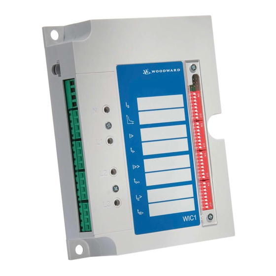
- Page 1 WIC1 – CT Powered Time Overcurrent and Earth Current Relay Original Technical Manual WIC1 (Revision L)
- Page 2 Woodward Technical Manual WIC1 Woodward reserves the right to update any portion of this publication at any time. Information provided by Woodward is believed to be correct and reliable. However, no responsibility is assumed by Woodward unless otherwise expressly undertaken.
-
Page 3: Table Of Contents
IMPORTANT DEFINITIONS ......................... 6 Electrostatic Discharge Awareness ......................7 Introduction ........................8 How to use this instruction ..........................8 Introductory remarks on the WIC1 ........................ 8 Product description ............................9 Handling, Installation and Outside Dimensions ............10 General information ............................ 10 3.1.1... - Page 4 Accessories for commissioning work ......................43 Criteria to be taken into account for protection devices fed by CTs ............44 Special features for the WIC1 test ......................44 Selection of the secondary test system ...................... 45 Checks during commissioning ........................45 6.6.1...
-
Page 5: Comments On The Manual
We do not accept any liability for damage and operational failures caused by operating errors or dis- regarding the directions of this manual. No part of this manual is allowed to be reproduced or passed on to others in any form, unless Woodward Kempen GmbH have approved in writing. -
Page 6: Important Definitions
Woodward Technical Manual WIC1 IMPORTANT DEFINITIONS The signal definitions shown below serve the safety of life and limb as well as for the appropriate operating life of the device. DANGER indicates a hazardous situation which, if not avoided, will result in death or serious injury. -
Page 7: Electrostatic Discharge Awareness
Guide for Handling and Protection of Electronic Controls, Printed Circuit Boards, and Modules. Woodward Kempen GmbH reserves the right to update any portion of this publication at any time. Infor- mation provided by Woodward Kempen GmbH is believed to be correct and reliable. However, no respon- sibility is assumed by Woodward Kempen GmbH unless otherwise expressly undertaken. -
Page 8: Introduction
How to use this instruction In this instruction the technical description of all WIC1 versions is included. The user is given a comprehensive in- sight into the various applications, the selection, installation, setting of parameters and putting into operation of the WIC1. -
Page 9: Product Description
The WIC1 is a CT-powered protection relay with inverse time and definite time protection characteristics and is specifically designed for switchboards with CBs and small rated output currents. Together the specific CTs and the WIC1 form a joint protective system. A low-energy coil is needed for realizing trip of the CB. -
Page 10: Handling, Installation And Outside Dimensions
3.1.1 Upkeep of the relay As a rule protection relays are of robust construction and the WIC1 in particular allows operation under extreme environmental conditions. But despite these facts, the WIC1 should be handled with the necessary care during in- stallation and commissioning. -
Page 11: Outside Dimensions
Technical Manual WIC1 Woodward Outside dimensions All WIC1 types are of standardized design. Weight WIC1: 700g Dimensions: (Width x Height x Depth) 125x170x40mm Connection Diagram for WIC1 gn/ge gn/ge gn/ge Schauzeichen Flag indicator Energiearme / low energy Auslösespule / tripping... -
Page 12: Connection Diagram For The Flag Indicator Wi-Sz
Woodward Technical Manual WIC1 Connection Diagram for the Flag Indicator WI-SZ Figure 3.2: Connection diagram WI-SZ4 flag indicator Figure 3.3: Connection diagram WI-SZ5 flag indicator DOK-TD-WIC1E, Rev. L... -
Page 13: Operating Instructions
(not available in WIC1-2F). The WIC1 is provided with an input for remote tripping to which 115 VAC or 230 VAC can be connected. Tripping is realized via the electric impulse output after max. 1 s. -
Page 14: User Interface
The setting values of the protective functions can be recorded directly at the protection relay. For the basic version WIC1-1 the adjustment of protective functions can only be done via the communication inter- face which is placed above the terminal blocks at the left of the device. -
Page 15: Wic1-4
Technical Manual WIC1 Woodward 4.2.2 WIC1-4 When compared to WIC1-1, the WIC1-4 provides an additional operator interface at its front panel. The functionality is the same as for the WIC1-1. Figure 4.2: WIC1-4 Note! For the operating software “WIC-Soft1” a separate description is available. -
Page 16: Wic1-2
For the relay version WIC1-2 setting of parameters via interface is not possible any more, but it is possible to read- out the stored fault values as well as the setting values of the WIC1. -
Page 17: Wic1-3
For the relay version WIC1-3 setting of parameters via interface is not possible any more, but it is possible to read- out the stored fault values as well as the setting values of the WIC1. -
Page 18: Cts For The Wic1
WIC1W2AS1 (i.e. without „E“) represents an inexpensive alternative. (For the lowest range 8 – 28 A, however, Woodward decided for quality reasons to not offer such an alternative.) If a higher accuracy is needed, or in case of a required earth current protection element it is recommended to always use an “E”-type CT (i.e. -
Page 19: Technical Data, Characteristics And Features
5.1.1 Minimal operating current and rated primary current In order to operate reliably, the WIC1 – as all CT-powered protection relays – needs a minimal current flowing con- stantly in one of the phases. This minimal current is the smallest rated CT current (IS) x 0.9 listed in table. -
Page 20: Phase Time Over Current Protection
Woodward Technical Manual WIC1 5.1.2 Phase time over current protection The following setting ranges and gradings apply for WIC1-1 and WIC1-4 devices. Here the parameters can only be set via a serial interface. Current Arithmetic averages measurement Threshold values I>... - Page 21 Technical Manual WIC1 Woodward For relay versions WIC1-2 and WIC1-3 the adjustment of values is done according to the tables listed below: Characteristic curve = HEX-Switch 2/DIP-Switch 1 (5 - 6) DIP 1-5 OFF ON OFF ON OFF ON OFF ON...
-
Page 22: Earth Current Protection
Current Internal calculated cumulative current formation 0.2 to 2.5 x IS in steps of 0.05 x IS E> when adjusting via the interface for the WIC1-1 Tripping time 0.1s to 20s in steps of 0.01 when adjusting via IE> the interface for the WIC1-1 IE>... -
Page 23: Default Settings
Technical Manual WIC1 Woodward Default Settings All WIC1 relay versions are set in our works at the smallest possible setting values. Is = smallest possible rated current (W1=8, W2=16A, W3=32A, W4=64A, W5=128A, W6=256A) Characteristic: Definite Time I> = 0.9 x In tI>... -
Page 24: Routine Safety Check
Fault value memory A fault value memory is integrated in the WIC1 where data of the latest fault occurrence is stored. The stored in- formation can only be read out via the PC interface. The following fault references are available: ... -
Page 25: Communication
The lockable opening at the housing of WIC1 and the 6-pole plug are of matching design. A 9V battery is integrated in the PC adapter. During reading out and writing of parameters the WIC1 is fed by the PC adapter The battery charging level is indicated by LED on the PC adapter. -
Page 26: Inputs And Outputs
The terminals for connection of the CT, the tripping coil of the external trip input as well as the flag indicator output are provided at the left side of the WIC1. Dependent on the relay type either screw-type terminals or screw-type plug-in terminals in 4-block arrangement are used. -
Page 27: Impulse Output For The Flag Indicator
It is not allowed to connect any active voltage to the trip coil output. 5.6.5 Measuring inputs for the CTs The measuring inputs of the WIC1 protection system are matching the allocated CTs. Also the power requirement of the relay and the CT output power match. -
Page 28: Technical Data
Woodward Technical Manual WIC1 Technical Data 5.7.1 Common Data Frequency: 45 Hz to 65 Hz Nominal: 50/60 Hz Thermal load capacity: Permanently: 2.5 x highest rated CT current 25 kA CT primary current 20 kA CT primary current Dynamic load capacity: 62.5 kA CT primary current... -
Page 29: Insulation Voltage Withstand
Technical Manual WIC1 Woodward 5.7.4 Insulation voltage withstand Test of withstand alternating voltage for 1 min: IEC 60255-5 2.5 kV Test of lightning surge voltage 1.2/50 µs, 0.5 J IEC 60255-5 5 kV 5.7.5 EMC Interference immunity against discharges of static electricity... -
Page 30: Ambient Conditions
Woodward Technical Manual WIC1 5.7.6 Ambient conditions Vibration and continuous vibration test DIN EN 60255-21-1 [05/96] 1/2 gn Class 2 Shock and continuous shock test DIN EN 60255-21-2 [05/96] 10/20 gn Class 2 Earthquake test DIN EN 60255-21-3 [11/95] 2 gn... -
Page 31: Outside Dimension Of Cts
The diameter A of the CT whole is 45 mm for type WIC1W1AS1 The diameter A of the CT whole is 50 mm for the types WIC1WE2AS1 and WIC1W2AS1 to WIC1W5AS1 Figure 5.3: Type WIC1-W2AS1 – WIC1-W5AS1 as panel mounting DOK-TD-WIC1E, Rev. L... - Page 32 Woodward Technical Manual WIC1 Type: WIC1W6AS1 Figure 5.4: Type WIC1W6AS1 as panel mounting Figure 5.5: Type WIC1-WxH1 as plug on type DOK-TD-WIC1E, Rev. L...
-
Page 33: Characteristics And Times
Technical Manual WIC1 Woodward Characteristics and times 5.8.1 Characteristic curves 1000 10.0 t[s] 0.05 5 6 7 8 910 Multiples of pick up setting * Figure 5.5: Normal Inverse *Multiples of pick up setting = Is * I> 1000 t[s] 10.0... - Page 34 Woodward Technical Manual WIC1 10000 1000 t[s] 10.0 0.05 0.05 0.01 5 6 7 8 910 Multiples of pick up setting * Figure 55.7: Extremely Inverse *Multiples of pick up setting = Is * I> I> I> I> I> t[s] >...
- Page 35 Technical Manual WIC1 Woodward 10000 1000 t[s] 10.0 0.05 0.05 5 6 7 8 910 Multiples of pick up setting * Figure 5.9: Long time inverse *Multiples of pick up setting = Is * I> 10000 1000 t[s] 10.0 0.01...
- Page 36 Woodward Technical Manual WIC1 10.0 t[s] 0.05 5 6 7 8 910 Multiples of pick up setting * Figure 5.2: RI-Inverse *Multiples of pick up setting = 100000 10000 1000 t[s] 10.0 0.01 5 6 7 8 910 Multiples of pick up setting * Figure 5.3: FR-fuse...
-
Page 37: Calculation Formula For Imt Characteristics
Technical Manual WIC1 Woodward 5.8.2 Calculation formula for IMT characteristics Normal Inverse: 0.14 ∙ �� [ �� ] �� = 0.02 �� − 1 �� × �� �� > Very Inverse: 13.5 ∙ �� [ �� ] �� = ��... -
Page 38: Flag Indicators
Woodward Technical Manual WIC1 5.8.3 Flag Indicators WI1SZ4 Technical Data 24V DC 10% Coil: - can be set electrically - can be reset mechanically Connector assignment Coil connection Core color mm² Function black 0.25 Gnd/Set black 0.25 Gnd/Set Cable connection length:... -
Page 39: Description Of The Application
As CT-powered protection relay the WIC1 is mainly used in MV switchboards with circuit breakers, protecting dis- tribution transformers in local and industrial networks. Due to its small size the WIC1 is very well suited for the use in compact switchboards. -
Page 40: Selection Of The Ct Transformation Voltage Ratio
With parameter Is the calculated rated current is preset in the protection relay. According to Table 5.1, IS currents of 88 A can be set for both CT types in relay versions WIC1-2 and WIC1-3. In the example shown below, the transformer can be operated with 1.1 times the rated current for 10 s. The setting value for I>... -
Page 41: Adjustment Instruction For Inverse Characteristic
= Tripping time of the short circuit element I>> This parameter serve to delay the trip of the WIC1 after a pick up occurs. The WIC1 trips when the pick up still exist at the time elapsed. = Pick up value of the earth fault element E>... - Page 42 Estimation of the tripping time at inverse characteristics The setting and estimation by the use of an inverse characteristic will be explained at the following example. Boundary condition: Operating current of the load (IS) WIC1-W3, 32 A – 112 A Selected CT ratio Characteristic Normal Inverse N-INV Starting point of the characteristic I>...
-
Page 43: Commissioning And Maintenance
(Grounding of the feeder). Accessories for commissioning work For commissioning of the protection system the following accessories should be available: For WIC1-1 and WIC1-4: an adapter WIC1PC3, and a PC with software Secondary testing system (see chapter 6.3ff) ... -
Page 44: Criteria To Be Taken Into Account For Protection Devices Fed By Cts
Is = lowest rated current Special features for the WIC1 test The WIC1 receives its supply energy out of the measuring circuit. Conditional on the circuit logic the WIC1 changes its measuring load in a cyclic way and that in a 1 kHz cycle. -
Page 45: Selection Of The Secondary Test System
When putting into operation, the wiring and setting of the protection relay should be checked. Here the person do- ing the commissioning work is assisted by the integrated test windings of the WIC1 protection system, which are on the front of the relay. Hence any wiring jobs as well as actions in the cable connection area can be disregarded. -
Page 46: Wic1 Adjustment
When the primary test method is used, the test current is impressed via the primary winding. When the secondary test method is used, the test current is impressed via the CD test winding. There are different standard CT types available for the WIC1. CT Type... -
Page 47: Test Currents
Technical Manual WIC1 Woodward 6.7.1 Test Currents The transformation ratio of primary currents to secondary currents of the CTs are equally proportionate as the test current via the CD winding to the secondary current. This means, no matter which CT type is in operation, for the secondary test always the same test values are used. -
Page 48: Switching Points For The Short-Circuit Step
Woodward Technical Manual WIC1 6.7.3 Switching points for the short-circuit step DIP 1-1 DIP 1-2 OFF OFF OFF OFF OFF OFF OFF OFF DIP 1-3 OFF OFF OFF OFF OFF OFF OFF OFF DIP 1-4 OFF OFF OFF OFF OFF OFF OFF OFF HEX switch I>>... -
Page 49: Special Features For Earth Current Tests
Functional description: In the WIC1 the earth current is calculated and cannot be measured. It is established from the geometrical amount of the three phase current values, more or less a numerical Holmgreen. If, for instant, a single-phase test current is impressed, the measuring value (tripping value) in the earth current path equals the current in the tested phase. -
Page 50: Test Procedure By Way Of Example
Technical Manual WIC1 Test procedure by way of example When testing the WIC1, the tests of the individual equipment should be carried out from the highest setting value to the smallest one. The order ought to be: 1) short circuit I>>... - Page 51 Technical Manual WIC1 Woodward Test step 3): Test of the over-current step I>: Settings: I> = 1.05 x Is tI> = EXIT I>> = 4.00 x Is tI>> = 0.10s IE> = EXIT tIE> = 0.2s Test to be carried out as described under “Test step 1”.
-
Page 52: Maintenance
6.10.2 Repair work The WIC1 is a hermetically sealed relay and so it is not possible to do any repair work at your end. Due to the optimized cost structure, however, repair in our works is also not beneficial. During the warranty period the protection relay is exchanged by us free of charge, provided the failure was not caused by external influences. -
Page 53: Product-Specific Features
Remote trip input for auxiliary voltage 230 V AC 115 V Remote trip input for auxiliary voltage 115 V A* Remote trip input N (earth) Centre earthing point WIC1 Electric pulse output +pole Electric pulse output, -pole Flag indicator output, +pole... -
Page 54: Current Transformer
Woodward Technical Manual WIC1 Current transformer Listed CT ranges in relation to the transformer rated currents 3.00 3.30 4.20 5.50 6.00 6.60 10.00 11.00 12.00 13.80 15.00 15.50 17.50 20.00 21.00 22.00 24.00 U[kV] 50.00 9,62 8,75 WIC1WE1AS1 75.00 14,43... -
Page 55: Annex
Technical Manual WIC1 Woodward 8. Annex Dimensional drawing relay Figure 8.1: Dimensional drawing Dimensional drawing flag indicator Figure 88.2: Flag indicator WI1SZ4 / WI1SZ5 DOK-TD-WIC1E, Rev. L... -
Page 56: Order Form
Woodward Technical Manual WIC1 Order form Multi characteristic time over current relay WIC1 3-phase current measuring I>;I>> self powered – parameter setting via serial interface – parameter setting via DIP switches – parameter setting via HEX switches – Parameter setting via interface, with LED and second operator interface Connection mode –... -
Page 57: Commissioning Form
Technical Manual WIC1 Woodward Commissioning form List of adjustments for WIC1 Project: Order No.: Functional group: Location: Component Identification: Relay Function: Date: Parameter Setting Default Actual Function Unit Setting Setting CT Type Rated CT current Char Trip characteristic DEFT I>... - Page 58 Woodward Technical Manual WIC1 Woodward Kempen GmbH Krefelder Weg 47 D – 47906 Kempen (Germany) Postfach 10 07 55 (P.O.Box) D – 47884 Kempen (Germany) Phone: +49 (0) 21 52 145 1 Internet www.woodward.com Sales Tel.: +49 (0) 21 52 145 331 or +49 (0) 711 789 54 510...
Need help?
Do you have a question about the WIC1 and is the answer not in the manual?
Questions and answers