
Subscribe to Our Youtube Channel
Related Manuals for Woodward XRI1-ER


Summary of Contents for Woodward XRI1-ER
- Page 1 XRI1-ER – Earth fault relay for isolated and compensated mains Manual XRI1-ER (Revision C)
- Page 2 Woodward Manual XRI1-ER Woodward reserves the right to update any portion of this publication at any time. Information provided by Woodward is believed to be correct and reliable. However, no responsibility is assumed by Woodward unless otherwise expressly undertaken. © Woodward 1994–2019...
-
Page 3: Table Of Contents
Manual XRI1-ER Woodward Contents Introduction and application ..................5 Features and characteristics ..................6 Design ..........................7 Connections ............................. 7 3.1.1 Analog input circuits ..........................7 3.1.2 Blocking input............................7 3.1.3 External reset input ..........................7 3.1.4 Output relays............................7 3.1.5... - Page 4 Checking the set values ......................... 28 Secondary injection test ......................... 29 7.4.1 Test equipment ..........................29 7.4.2 Test circuit of XRI1-ER ........................29 7.4.3 Checking the input circuits and measured values ................31 7.4.4 Checking the operating and resetting values of the relay ..............31 7.4.5...
-
Page 5: Introduction And Application
Very often the XRI1-ER can be found as backup protection at the central earthing point of the system. It detects all earth faults occuring in the system. In this case the trip delay selected must exceed the longest time delay setting of any other earthing protection used in the system. -
Page 6: Features And Characteristics
Switch failure protection. Free assignment of output relays. Serial data exchange via RS485 interface possible; alternatively with Woodward RS485 Pro-Open Data Protocol and Modbus Protocol. Suppression of indication after an activation (LED flash). TD_XRI1-ER_12.03, Rev. C... -
Page 7: Design
By applying the aux. voltage C2/C2L or C2/C2H, indication and output relays are reset. (see chapter 6.3) 3.1.4 Output relays The XRI1-ER is equipped with 5 output relays. Apart from the relay for self-supervision, all protective functions can be optionally assigned: ... -
Page 8: Data Communication
Manual XRI1-ER 3.1.5 Data communication For data communication with a central control system the XRI1-ER relay is provided with a serial interface RS485. Simplified and fast reading and changing of parameters and measuring values can be achieved by HTL/PL-Soft4, which will be provided on request together with the relay. -
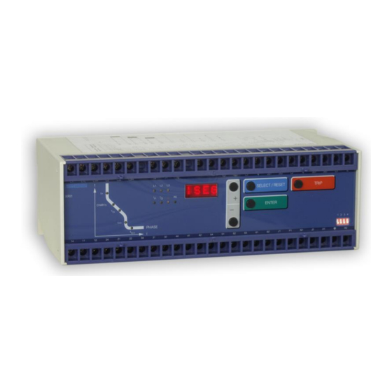
Page 9: Front Plate
The front plate of protection relays comprises the following operation and indication elements: Alphanumerical display (4 Digits) Push buttons for setting and other operations LEDs for measured value indication and setting Figure 3.4: Front plate XRI1-ER TD_XRI1-ER_12.03, Rev. C... -
Page 10: Display
Woodward Manual XRI1-ER 3.2.2 Display Function Display shows Pressed push button Corresponding Normal operation Measured operating values Actual measured <SELECT/RESET> with regard values, one time for each to directional fea- ture Measuring range overflow max. <SELECT/RESET> Setting values: (I Current settings Trip <SELECT/RESET>... -
Page 11: Leds
The LED left from the display, E is partially bi-colored, the green indicating measuring, and the red fault indica- tion. XRI1-ER with directional feature have a LED (green- and red arrow) for the directional display. At pickup/trip and parameter setting the green LED lights up to indicate the forward direction, the red LED indicates the re- verse direction. -
Page 12: Working Principle
Digital circuits The essential part of the XRI1-ER relay is a powerful microcontroller. All of the operations, from the analog digi- tal conversion to the relay trip decision, are carried out by the microcontroller digitally. The relay program is lo- cated in an EPROM (Electrically-Programmable-Read-Only-Memory). -
Page 13: Earth Fault Protection
4.3.2 System earth fault protection With the generator neutral point earthed as shown in figure 4.2, the XRI1-ER picks up only to earth faults in the power system connected to the generator. It does not pick up to earth faults on the generator terminals or in generator stator. -
Page 14: Earth-Fault Directional Feature
Woodward Manual XRI1-ER Earth-fault directional feature A built-in earth-fault directional element is available for applications to power networks with isolated or with arc suppressing coil compensated neutral point. For earth-fault direction detection it is mainly the question to evaluate the power flow direction in zero sequence system. - Page 15 Manual XRI1-ER Woodward Figure 4.3: Phase position between the residual voltage and zero sequence current for faulted and non-faulted lines in case of isolated systems (sin φ) - residual voltage - zero sequence current - capacitive component of zero sequence current - resistive component of zero sequence current By calculating the reactive current component (sin φ...
- Page 16 Woodward Manual XRI1-ER Figure 4.4: Phase position between the residual voltage and zero sequence current for faulted and non-faulted lines in case of compensated systems (cos φ) - residual voltage - zero sequence current - inductive component of zero sequence current (caused by Petersen coil)
-
Page 17: General Operations And Settings
Manual XRI1-ER Woodward 5. General operations and settings For adjustment of the unit the transparent cover has to be opened as illustrated. Do not use force! The trans- parent cover has two inserts for labels. Figure 5.1: How to open the transparent cover... -
Page 18: Indication Of Measuring Values And Fault Data
Woodward Manual XRI1-ER 5.1.1 Indication of measuring values and fault data Indication in faultless condition In normal operation the display always shows WW. After pressing the push button <SELECT/RESET> the dis- play switches cyclically to the next measuring value. After the measuring values had been indicated the set-ting parameters are displayed. -
Page 19: Dip Switches
Manual XRI1-ER Woodward Dip switches Behind the front plate of the XRI-ER relay there is one dip switch to preset the following functions: Password programming Output relay functions The following table 5.1 shows the position and designation of the code jumpers: 5.2.1 Function of the output relays... -
Page 20: Reset
The XRI1-ER-relay is delivered with the preset password "++++", it can be programmed new with dip switch 1: Switch on dip switch 1. After power on and pressing any push button, the relay XRI1-ER inquires for a new password. The text "PSW?" appears on the display. The new password is entered by any combination of the push buttons <SELECT>... -
Page 21: Relay Setting Principle
5.5.2 Blocking the protection function The blocking function of the XRI1-ER-relays can be set according to requirement. When pressing push buttons <ENTER> and <TRIP> at the same time the blocking mode is entered. -
Page 22: Display Of Software Version And Test-Trip
Low/high range of functions blocking and reset The XRI1-ER have a wide-range power supply unit al-lowing to choose a suitable supply voltage. The operating threshold of the blocking and reset inputs, however, has to be defined by taking the supply voltage into account. -
Page 23: Operations And Settings
Manual XRI1-ER Woodward 6. Operations and settings Setting procedure After push button <SELECT/RESET> has been pressed, always the next measuring value is indicated. Firstly the operating measuring values are indicated and then the setting parameters. By pressing the <ENTER> push button the setting values can directly be called up and changed. -
Page 24: Tripping Time For The Earth Overcurrent Stage
Woodward Manual XRI1-ER 6.1.5 Tripping time for the earth overcurrent stage (t IE> When the "Definite Time" tripping characteristic is adjusted, the independent tripping time will be shown on the display in seconds (e.g. 0.35 = 0.35 seconds). This value can be adjusted in steps by means of keys <+><->. -
Page 25: Circuit Breaker Failure Protection T
Manual XRI1-ER Woodward 6.1.9 Circuit breaker failure protection t CBFP The CB failure protection is based on supervision of phase currents during tripping events. Only after tripping this protective function becomes active. The test in this case by supervision of the earth current criterion is whether earth currents are dropped to <1% x IN within the time t... -
Page 26: Blocking The Protection Functions And Assignment Of The Output Relays
Assignment of the output relays: Unit XRI1-ER has five output relays. The fifth output relay is provided as permanent alarm relay for self supervi- sion is normally on. Output relays 1 - 4 are normally off and can be assigned as alarm or tripping re-lays to the current functions which can either be done by using the push buttons on the front plate or via serial interface RS485. -
Page 27: Indication Of Measuring And Fault Values
Manual XRI1-ER Woodward Note: A form is attached to this description where the set-ting requested by the customer can be filled-in. This form is prepared for fax transmission and can be used for your own reference as well as for telephone queries. -
Page 28: Relay Testing And Commissioning
Woodward Manual XRI1-ER 7. Relay testing and commissioning The test instructions following below help to verify the protection relay performance before or during commis- sioning of the protection system. To avoid a relay damage and to ensure a correct relay operation, be sure that: ... -
Page 29: Secondary Injection Test
The other input energizing quantity (current) and phase angle shall be appropriately varied. XRI1-ER is a three phase directional time overcurrent relay with relay connection angle of -0°. The relay input currents and their corresponding reference voltages are shown in table 7.1 (refer to Fig. 4.2):... - Page 30 Woodward Manual XRI1-ER In order to test the directional feature, parameters have to be set in compliance with table 7.2. Then a test volt- age equivalent to the rated voltage is connected to terminals L1/N1 and a current of 0.4 x In is impressed upon the current inputs 1E1/1E2.
-
Page 31: Checking The Input Circuits And Measured Values
0.3% or 0.03% In. By using an RMS-metering instrument, a greater deviation may be ob-served if the test cur- rent contains harmonics. Because the XRI1-ER relay measures only the fundamental component of the input signals, the harmonics will be rejected by the internal DFFT-digital filter. Whereas the RMS-metering instrument measures the RMS-value of the input signals. -
Page 32: Checking The External Blocking And Reset Functions
Woodward Manual XRI1-ER 7.4.7 Checking the external blocking and reset functions The external blocking input inhibits e. g. the function of the high set element of the phase current. To test the blocking function apply auxiliary supply voltage to the external blocking input of the relay (terminals C1/C1L or C1/C1H). -
Page 33: Primary Injection Test
In case of a XRI1-ER re-lay with directional feature, the active and reactive parts of the measured currents may be checked and the actual power factor may be calculated and compared it with the cosφ... -
Page 34: Technical Data
Woodward Manual XRI1-ER 8. Technical data Measuring input circuits Rated data: Nominal current I 1A or 5A Nominal voltage U 100 V, 230 V, 400 V Nominal frequency f 50 Hz; 60 Hz adjustable Power consumption in current circuit: at I = 1 A 0.2 VA... -
Page 35: Setting Ranges And Steps
Manual XRI1-ER Woodward Setting ranges and steps 8.3.1 Earth fault protection Setting range Step Tolerance > 0.01...0.45 x I (EXIT) (ER) 0.001; 0.002; 0.005; 0.01 x I ±5 % from set value or 0.01%; 0.02%; 0.05%; 0.1% x I ±0.3 % I (ER);... -
Page 36: Output Relays
Woodward Manual XRI1-ER Output relays Contacts: 2 relays with 2 changeover contacts; 3 relays with 1 changeover contact The output relays have with the following characteristics: maximum breaking capacity 250 V AC / 1500 VA / continuous current 6 A... -
Page 37: System Data And Test Specifications
Manual XRI1-ER Woodward System data and test specifications Design standards: Generic standard: EN 50082-2, EN 50081-1 Product standard: EN 60255-6, IEC 255-4, BS142 Specified ambient service temperature limits in operation: -25°C to +70°C storage: -10°C to +55°C Moisture-carrying capacity class F... -
Page 38: Relay Case
Technical data subject to change without notice! Relay case Relay XRI1-ER is designed to be fastened onto a DIN-rail acc. to DIN EN 50022, the same as all units of the PROFESSIONAL LINE. The front plate of the relay is protected with a sealable transparent cover (IP40). -
Page 39: Order Form
Manual XRI1-ER Woodward 9. Order form Earth fault current relay XRI1 (with display and serial interface) Earth current measuring for isolated/compensated sys- tems very sensitive for isolated/compensated systems Rated current in earth circuits Directional feature in earth path Rated voltage in earth circuits... - Page 40 Woodward Manual XRI1-ER Setting list XRI1-ER Note ! All settings must be checked at site and should the occasion arise, adjusted to the object/item to be protected. Project: Woodward job.-no.: Function group: = Location: + Relay code: - Relay functions:...
- Page 41 Manual XRI1-ER Woodward Setting of code jumpers Code jumper Default Actual Default Actual Default Actual setting setting setting setting setting setting Plugged Not plugged Assignment of the output relays: Function Relay 1 Relay 2 Relay 3 Relay 4 Default Actual...
- Page 42 Woodward Kempen GmbH Krefelder Weg 47 D – 47906 Kempen (Germany) Postfach 10 07 55 (P.O.Box) D – 47884 Kempen (Germany) Phone: +49 (0) 21 52 145 1 Internet www.woodward.com Sales Phone: +49 (0) 21 52 145 216 or 342 Telefax: +49 (0) 21 52 145 354 e-mail: salesEMEA_PGD@woodward.com...
Need help?
Do you have a question about the XRI1-ER and is the answer not in the manual?
Questions and answers