Table of Contents
Advertisement
Quick Links
Advertisement
Table of Contents

Subscribe to Our Youtube Channel
Related Manuals for Woodward PROFESSIONAL Series


Summary of Contents for Woodward PROFESSIONAL Series
- Page 1 XRN2 – Mains decoupling relay Manual XRN2 (Revision D)
- Page 2 Woodward Manual XRN2 Woodward reserves the right to update any portion of this publication at any time. Information provided by Woodward is believed to be correct and reliable. However, no responsibility is assumed by Woodward unless otherwise expressly undertaken. © Woodward 1994–2019...
-
Page 3: Table Of Contents
Manual XRN2 Woodward Contents Introduction and application ..................5 Features and characteristics ..................6 Design ..........................7 Connections ............................. 7 3.1.1 Analog input circuits ..........................7 3.1.2 Blocking input............................7 3.1.3 Reset input ............................7 3.1.4 Output relays............................7 3.1.5 Power Supply ............................ - Page 4 Woodward Manual XRN2 6.3.1 Min./Max.- values ..........................34 Reset ..............................35 Relay testing and commissioning ................36 Power-On ............................... 36 Testing the output relays ........................36 Checking the set values ......................... 37 Secondary injection test ......................... 37 7.4.1 Test equipment ..........................37 7.4.2...
-
Page 5: Introduction And Application
Manual XRN2 Woodward 1. Introduction and application The XRN2 is a universal mains decoupling device and covers the protection requirements from VDEW and most other utilities for the mains parallel operation of power stations. Over/ and undervoltage protection ... -
Page 6: Features And Characteristics
Woodward Manual XRN2 2. Features and characteristics Microprocessor technology with watchdog Effective analog low pass filter for suppressing harmonics when measuring frequency and vector surge Digital filtering of the measured values by using discrete Fourier analysis to suppress higher harmonics and d.c. -
Page 7: Design
Manual XRN2 Woodward 3. Design Connections Figure 3.1: Connection diagram XRN2-1 and XRN2-2 3.1.1 Analog input circuits The analog input voltages are galvanically decoupled by the input transformers of the device, then filtered and finally fed to the analog digital converter. The measuring circuits can be applied in star or delta connection (refer to chapter 4.3.1). -
Page 8: Power Supply
Woodward Manual XRN2 3.1.5 Power Supply The XRN2 has a wide range power supply. It can connect to AC or DC supply. The connection for DC supply don’t need to consider for polarity. 3.1.6 Data communication For data communication with a central control system the XRN2 relay is provided with a serial interface RS485. -
Page 9: Front Plate
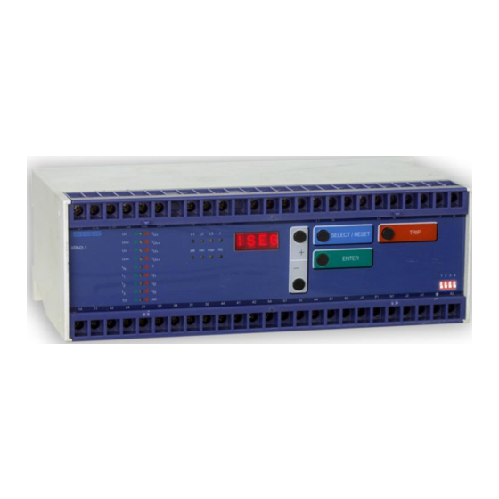
Manual XRN2 Woodward Front plate 3.2.1 Indication- and operation elements The front plate of the XRN2-protection relay comprises the following operation and indication elements: Alphanumerical display (4 Digits) Push buttons for setting and other operations LEDs for measured value indication and setting Figure 3.4: Front plate XRN2... -
Page 10: Display
Woodward Manual XRN2 3.2.2 Display Function Display shows Pressed pushbutton Corre- Type of sponding relay Normal operation all types Measured operating values Actual measured val- <SELECT/RESET> one L1, L2, L3, time for each value f, min, max Min. and max. values... - Page 11 Manual XRN2 Woodward Function Display shows Pressed pushbutton Corre- Type of sponding relay + L1, L2 vector surge tripping value in de- <SELECT/RESET><+><-> XRN2-1 gree one time for each phase or L3 Save parameter? SAV? <ENTER> Save parameter! SAV! <ENTER>...
-
Page 12: Leds
Woodward Manual XRN2 3.2.3 LEDs All LEDs (except LED RS, min and max) are two-colored. The LEDs on the left side, next to the alpha-numerical display light up green during measuring and red after tripping. The LEDs below the push button <SELECT/RESET> are lit green during setting and inquiry procedure of the setting values which are printed on the left side next to the LEDs. -
Page 13: Parameter Settings
Manual XRN2 Woodward 3.2.6 Parameter settings Setting parameter XRN2-1 XRN2-2 Δ/Y U< tU< U<< tU<< U> tU> U>> tU>> UB< RS485/ Slave Table 3.2: Sequence of parameter setting of the two relay types DOK-TD-XRN2, Rev. D... -
Page 14: Working Principle
Woodward Manual XRN2 4. Working principle Analog circuits The input voltages are galvanically insulated by the input transformers. The noise signals caused by inductive and capacitive coupling are suppressed by an analog R-C filter circuit. The analog voltage signals are fed to the A/D-converter of the microprocessor and transformed to digital signals through Sample- and Hold- circuits. -
Page 15: Selection Of Star Or Delta Connection
Manual XRN2 Woodward 4.3.1 Selection of star or delta connection All connections of the input voltage transformers are led to screw terminals. The nominal voltage of the device is equal to the nominal voltage of the input transformers. Dependent on the application the input transformers can be connected in either delta or star. -
Page 16: Principle Of Frequency Supervision
Woodward Manual XRN2 Principle of frequency supervision The frequency element of XRN2 protects electrical generators, consumers or electrical operating equipment in general against over- or underfrequency. The relay has independent three frequency elements f with a free choice of parameters, with separate ad- justable pickup values and delay times. -
Page 17: Vector Surge Supervision (Xrn2-1)
Manual XRN2 Woodward Vector surge supervision (XRN2-1) The vector surge supervision protects synchronous generators in mains parallel operation due to very fast de- coupling in case of mains failure. Very dangerous are mains auto reclosings for synchronous generators. The mains voltage returning after 300 ms can hit the generator in asynchronous position. A very fast de-coupling is also necessary in case of long time mains failures. - Page 18 Woodward Manual XRN2 Important Information on the Vector Surge Supervision: Single Phase Vector Supervision "1-of-3" ("1Ph" on the Display) Within the Area „Safe Area“ the trip decision depends on the set Angle „Delta phi“ only (please refer to figure Single Phase Vector Surge Supervision).
-
Page 19: Measuring Principle Of Vector Surge Supervision
Manual XRN2 Woodward 4.6.1 Measuring principle of vector surge supervision When a synchronous generator is loaded, a rotor displacement angle is build between the terminal voltage (mains voltage U1) and the synchronous internal voltage (Up). Therefore a voltage is difference ΔU is built be- tween Up and U1 (Fig. - Page 20 Woodward Manual XRN2 Figure 4.6: Equivalent circuit at mains failure In case of mains failure or auto reclosing the generator suddenly feeds a very high consumer load. The rotor displacement angle is decreased repeatedly and the voltage vector U changes its direction (U ') (Fig.
- Page 21 Manual XRN2 Woodward Figure 4.8: Voltage vector surge As shown in the voltage/time diagram the instantaneous value of the voltage jumps to another value and the phase position changes. This is named phase or vector surge. The XRN2-1 measures the cycle duration. A new measuring is started at each voltage zero passage. The measured cycle duration is internally compared with a quartz stable reference time and from this the deviation of the cycle duration of the voltage signal is ascertained.
- Page 22 Woodward Manual XRN2 Application hint Although the vector surge relay guarantees very fast and reliable detection of mains failures under nearly all op- erational conditions of mains parallel running alternators, the following borderline cases have to be considered accordingly: a) None or only insignificant change of power flow at the utility connection point during mains failures.
-
Page 23: Voltage Threshold Value For Frequency Measuring
Manual XRN2 Woodward Voltage threshold value for frequency measuring At low measuring voltages, e.g. during generator start-up, frequency and vector surge or df/dt-measuring is per- haps not desired. , df/dt or Δ are blocked if the meas- By means of the adjustable voltage threshold value U <, functions f... -
Page 24: Operation And Setting
Woodward Manual XRN2 5. Operation and setting For adjustment of the unit the transparent cover has to be opened as illustrated. Do not use force! The trans- parent cover has two inserts for labels. Figure 5.1: How to open the transparent cover... -
Page 25: Indication Of Measuring Values And Fault Data
Manual XRN2 Woodward 5.1.1 Indication of measuring values and fault data Indication in faultless condition In normal operation the display always shows WW. After pressing the push button <SELECT/RESET> the dis- play switches cyclically to the next measuring value. After the measuring values had been indicated the set-ting parameters are displayed. -
Page 26: Dip Switches
Woodward Manual XRN2 DIP switches On the front plate of the XRN2-relay there is one DIP switch to preset the following functions: Password programming Output relay functions The figure 3.1 shows the position and designation of the code jumpers: 5.2.1 Function of the output relays... -
Page 27: Reset
Manual XRN2 Woodward Reset Manual reset By pressing push button <RESET/SELECT> for some time (about 3 s). External reset-input C2/C2L or C2/C2H The external reset input has the same function as the <SELECT/RESET> push button on the front plate. Con- necting auxiliary voltage to this input, the unit can be reset, provided that the fault is removed. -
Page 28: Relay Setting Principle
Woodward Manual XRN2 After the password is given correctly, parameter setting is permitted for five minutes. This means: For a subse- quent parameter setting, as long as it is made within five minutes after the password input, a renewed password input is not required. -
Page 29: Low/High Range Of Functions Blocking And Reset
Manual XRN2 Woodward Low/High range of functions blocking and reset All relays of the PROFESSIONAL LINE have a wide-range power supply unit allowing to choose a suitable sup- ply voltage. The operating threshold of the blocking and reset inputs, however, has to be defined by taking the supply voltage into account. -
Page 30: Special Settings
Woodward Manual XRN2 6. Special settings Adjustable parameters The following parameters can be set by the user him-self: XRN2-1 and XRN2-2: Δ/Y changing of input transformer connection U< threshold for undervoltage tU< tripping delay for undervoltage U<< threshold for undervoltage tU<<... -
Page 31: Setting Procedure
Manual XRN2 Woodward Setting procedure In this paragraph the settings for all relay parameters are described in detail. For parameter setting a pass-word has to be entered first (please refer to 5.4). 6.2.1 Parameter setting of over- and undervoltage supervision The setting procedure is guided by two colored LEDs. -
Page 32: Threshold Of Frequency Supervision
Woodward Manual XRN2 6.2.4 Threshold of frequency supervision The frequency supervision of XRN2 has three frequency elements independent from each other. Acc. to setting the pickup value above or below the nominal frequency, these elements can be used for over- or under fre- quency supervision. -
Page 33: Parameter Setting Of Frequency Gradient (Xrn2-2)
Manual XRN2 Woodward Threshold for the vector surge supervision When the pickup value of the vector surge supervision is set, a value in angular degree is indicated at the dis- play. The pickup value requested can be adjusted by pushbuttons <+> and <-> in the range of 2° to 22°. LED Δ... -
Page 34: Indication Of Measuring Values
Woodward Manual XRN2 Indication of measuring values In normal operation the following measuring values can be displayed. Voltages (LED L1, L2, L3 green) In star connection all phase-to-neutral voltages In delta connection all phase-to-phase voltages Frequency (LED f green + L1, L2 or L3 green; XRN2-1) Vector surge (LED Δ... -
Page 35: Reset
Manual XRN2 Woodward Reset All relays have the following three possibilities to reset the display of the unit as well as the output relay at switch position 3=ON. Manual Reset Pressing the push button <SELECT/RESET> for some time (about 3 s) Electrical Reset ... -
Page 36: Relay Testing And Commissioning
Woodward Manual XRN2 7. Relay testing and commissioning The following test instructions should help to verify the protection relay performance before or during commis- sioning of the protection system. To avoid a relay damage and to ensure a correct relay operation, be sure that: ... -
Page 37: Checking The Set Values
Manual XRN2 Woodward Checking the set values By repeatedly pressing the push button <SELECT>, all relay set values may be checked. Set value modification can be done with the push button <+><-> and <ENTER>. As relay input energizing quantities, three phase volt-ages should be applied to XRN2 relay input circuits. De- pending on the system conditions and the voltage transformer used, three voltages can be connected to the re- lay input circuits with either star or delta connection. -
Page 38: Checking The Input Circuits And Measuring Functions
Woodward Manual XRN2 For testing the vector surge function of the relay, a test circuit which can produce phase angle change (vector surge) is required to simulate mains failures (please refer to chapter 7.4.8). For testing the df/dt function of the relay, a special test equipment is required, which produces a constant rate of change of frequency. -
Page 39: Checking The Relay Operating Time Of The Over/Undervoltage Functions
Manual XRN2 Woodward 7.4.5 Checking the relay operating time of the over/undervoltage functions To check the relay's operating time, a timer must be connected to the trip output relay contact (Contact termi- nals D1/E1). The timer should be started simultaneously with the voltage change from sound condition to a faulty condition and stopped by the trip relay contact. -
Page 40: Checking The Vector Surge Function
Woodward Manual XRN2 7.4.8 Checking the vector surge function With the help of an advanced relay test equipment a phase shift (vector surge) on the voltage signal can be ob- tained to test the vector surge function of XRN2 relay. If there is no such testing facility available, a very simple simulation circuit may be used to test the vector surge function of the relay with a sufficient accuracy. -
Page 41: Checking The External Blocking And Reset Functions
Manual XRN2 Woodward 7.4.9 Checking the external blocking and reset functions The external blocking input is free programmable by the user. To test the blocking function apply auxiliary supply voltage to the external blocking input of the relay (terminals C1/C1L or C1/C1H). Inject a test voltage which could cause tripping for the testes functions. Observe that there is no trip and alarm for those functions. -
Page 42: Technical Data
Woodward Manual XRN2 8. Technical data Measuring input circuits Rated data: Nominal voltage U 100 V, 230 V, 400 V Nominal frequency f 40 - 70 Hz Power consumption in voltage circuit: <1 VA Thermal rating: continuously 2 x U... -
Page 43: Setting Ranges And Steps
Manual XRN2 Woodward Setting ranges and steps Function Para- Setting range Steps Tolerance meter U</<< U</<< = 100 V: 1% of set value 2...200 V (EXIT) = 230 V: or <0.3% U 2...460 V (EXIT) = 400 V: 4...800 V (EXIT) 1% or... -
Page 44: Output Relays
Woodward Manual XRN2 Output relays Relay Trip relays/change-over contacts Alarm relays/change-over contacts type XRN2 Table 8.2: Output relays The output relays have with the following characteristics: maximum breaking capacity 250 V AC / 1500 VA / continuous current 6 A... -
Page 45: System Data And Test Specifications
Manual XRN2 Woodward System data and test specifications Design standards: Generic standard: EN 6100-6-2, EN 61000-6-3 Product standard: IEC 60255-6, EN 50178 Specified ambient service temperature limits in operation: -10°C to +55°C storage : -25°C to +70°C Moisture-carrying capacity IEC 60068-2-78: rel. -
Page 46: Relay Case
Woodward Manual XRN2 Mechanical test: Shock: Class 1 as per IEC 60255-21-2 Vibration: Class 1 as per IEC 60255-21-1 Degree of protection: IP40 Overvoltage class: Weight: 1.6 kg Relay case material: self-extinguishing Technical data subject to change without notice! Relay case Relay XRN2 is designed to be fastened onto a DIN-rail acc. -
Page 47: Order Form
Manual XRN2 Woodward 9. Order form Mains decoupling relay XRN2- with voltage-, frequency and vector surge supervision Voltage, frequency and df/dt-supervision Rated voltage: 100 V 230 V 400 V DOK-TD-XRN2, Rev. D... - Page 48 Woodward Manual XRN2 Setting list XRN2 Project: Woodward job.-no.: Function group: = Location: + Relay code: - Relay functions: Password: Function Unit Default Actual settings settings Δ/Y input transformer connection U< pickup value for undervoltage element (low set) 90/210/360* <...
- Page 49 Manual XRN2 Woodward Ext. blocking parameter stetting Δ U< U<< U> U>> df/dt Default setting BLOC BLOC NO_B NO_B BLOC BLOC NO_B BLOC BLOC Actual setting Setting of dip switches switch Default Actual Default Actual Default Actual Default Actual setting...
- Page 50 Woodward Kempen GmbH Krefelder Weg 47 D – 47906 Kempen (Germany) Postfach 10 07 55 (P.O.Box) D – 47884 Kempen (Germany) Phone: +49 (0) 21 52 145 1 Internet www.woodward.com Sales Phone: +49 (0) 21 52 145 216 or 342 Telefax: +49 (0) 21 52 145 354 e-mail: salesEMEA_PGD@woodward.com...
Need help?
Do you have a question about the PROFESSIONAL Series and is the answer not in the manual?
Questions and answers