
Related Manuals for CommScope FDH 5000 144


Summary of Contents for CommScope FDH 5000 144
- Page 1 Installation Instructions TC-1437-IP Rev. C, April 2024 www.commscope.com FDH 5000 144, 288 Indoor/Outdoor Cabinet User Manual 24207-A www.commscope.com 860657178 Rev B...
- Page 2 GORE is a registered trademark of W. L. Gore & Associates, Inc. All trademarks identified by ® or ™ are registered trademarks or trademarks, respectively, of CommScope, Inc. This document is for planning purposes only and is not intended to modify or supplement any specifications or warranties relating to CommScope products or services.
-
Page 3: Table Of Contents
TECHNICAL ASSISTANCE ..............40 Page iii © 2024, CommScope, Inc. -
Page 4: About This Manual
RELATED PUBLICATIONS Listed below are related manuals and their publication numbers. Copies of these publications can be ordered by contacting the CommScope Technical Assistance Center at 1.800.830.5056, or by e-mail to TAC.Americas@commscope.com. Title... -
Page 5: Standards Certification
The acronyms and abbreviations used in this manual are detailed in the following list: American Wire Gauge Centigrade Fahrenheit Fiber Distribution Hub FTTP Fiber To The Premises Inside Diameter Outside Plant Plug and Play Reduced Bend Radius Return Material Authorization Page vii © 2024, CommScope, Inc. -
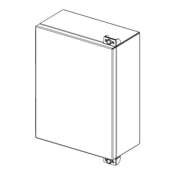
Page 6: Description
The FDH 5000 cabinet is a secure, above-ground, indoor/outdoor fiber optic distribution cabinet that is designed to hold the splitters, adapters required for Fiber To The Premises (FTTP) network applications. Figure 1. FDH 5000 Cabinet Page 1 © 2024, CommScope, Inc. - Page 7 The FDH 5000 cabinet is designed to be installed in either an indoor or an outdoor environment. When used indoors, installer must follow NEC guidelines related to cable use within a building. Page 2 © 2024, CommScope, Inc.
- Page 8 1 x 16 14.1 dB with APC 1 x 32 17.3 dB with APC 1 x 64 21 dB with APC 2 x 16 14.7 dB with APC 2 x 32 18 with APC Page 3 © 2024, CommScope, Inc.
- Page 9 SIDE 26.5 IN FRONT VIEW VIEW (67,3 CM) 13.25 IN 7.5 IN (33,7 CM) (19,1 CM) TOP VIEW 12.2 IN (31,75 CM) º 25.6 IN (65 CM) 24212-B Figure 2. FDH 5000 Cabinet Dimensions Page 4 © 2024, CommScope, Inc.
-
Page 10: Before Starting The Installation
2. Open the cabinet door (requires 216B key tool) and check for missing ship-along parts (see installation drawing included with cabinet) or broken parts. If there are damages, contact CommScope (see Section 11) for an RMA (Return Material Authorization) and to reorder if replacement is required. -
Page 11: Grounding The Cabinet And Osp Cables
It is the installer’s responsibility to ensure that all cables and external components used in the installation are also appropriate for the environment and will meet any standards requirements (including grounding, flammability, temperature, humidity, corrosion, etc.) that may apply. Page 6 © 2024, CommScope, Inc. -
Page 12: Craft Requirements
The FDH 5000 Cabinet may be assembled, mounted, and installed by one trained craftsperson. Cabinet Mounting The next two sections provide instructions for the mounting the cabinet on either a utility pole or a wall. Use whichever procedure is appropriate for the installation. Page 7 © 2024, CommScope, Inc. -
Page 13: Mounting The Cabinet On A Wooden Utility Pole
3. Drill a 9/32-inch hole in the pole at each of the locations marked in step 2. 4. Secure the mounting bracket to the pole using the two 3/8-inch x 2-inch lag screws. Tighten lag screws securely. Page 8 © 2024, CommScope, Inc. - Page 14 1/2-inch threaded rod or through-bolt be used to secure the mounting bracket to the pole. Refer to Figure 4 for the recommended installation procedure. Note: Cable conduit is recommended to contain the fiber cable starting at the ground to the cabinet. Page 9 © 2024, CommScope, Inc.
- Page 15 7. Tighten the partially installed cap screw at the bottom of the cabinet using the 216B key tool. Note: A cup washer is included with the cap screw to provide tamper resistance. Page 10 © 2024, CommScope, Inc.
-
Page 16: Grounding Wire Connection To Cabinet
Grounding Wire Connection To Cabinet Use the following procedure to connect the grounding wire to the cabinet: 1. Locate the cabinet grounding lug which is mounted on the underside of the cabinet as shown in Figure Page 11 © 2024, CommScope, Inc. - Page 17 5. Cut the grounding wire to length and connect it to the ground source as specified by local code or practice. Warning: Failure to properly tighten the screw on the grounding lug could result in improper grounding of the cabinet and result in performance or safety issues. Page 12 © 2024, CommScope, Inc.
-
Page 18: Mounting The Cabinet On A Wall
3. Using the mounting bracket as a guide, mark the location of the bracket mounting holes on the plywood backer. 4. Drill a 3/32-inch pilot hole in the backer board at each of the locations marked in step 3. Page 13 © 2024, CommScope, Inc. - Page 19 8. Securely tighten the partially installed cap screw at the bottom of the cabinet using the 216B key tool. Note: A cup washer is included with the cap screw to provide tamper resistance. Page 14 © 2024, CommScope, Inc.
-
Page 20: Masonry Wall Mounting Procedure
• 3/8-inch x 1-1/2 inch hex head capscrew (2) • 3/8-inch flat washer (2) • 3/8-inch lock washer (2) • Drill • 5/8-inch masonry drill bit (check hole size with concrete anchor manufacturer) • 9/16-inch wrench • 216B key tool (accessory) Page 15 © 2024, CommScope, Inc. - Page 21 8) fits into the two slots at the top of the mounting bracket. The partially installed cap screw at the bottom of the mounting bracket fits into the slotted tab at the bottom of the cabinet. Page 16 © 2024, CommScope, Inc.
-
Page 22: Grounding Wire Connection To Cabinet
5. Cut the grounding wire to length and connect it to the ground source as specified by local code or practice. Warning: Failure to properly tighten the screw on the grounding lug could result in improper grounding of the cabinet and result in performance or safety issues. Page 17 © 2024, CommScope, Inc. -
Page 23: Ground Mounting The Cabinet
Warning: Use appropriate lifting equipment when moving or installing the cabinet. Do not stand under a cabinet as it is being hoisted into position for mounting. A failure of the lifting equipment could result in serious personal injury. Page 18 © 2024, CommScope, Inc. - Page 24 WASHERS (4) FMS COVER ISOLATION GASKET FMS ADAPTER COVER GROUNDING WIRE 22677-A Figure 11. Mounting the 288 Termination Cabinet With Splicing on the FMS Use the following procedure to mount the cabinet on the FMS: Page 19 © 2024, CommScope, Inc.
- Page 25 If a spacer/riser was not installed, leave the isolation gasket (installed in step 4) in place on the adapter cover. Page 20 © 2024, CommScope, Inc.
-
Page 26: Mounting The Cabinet On The Pad Mount
Use only the Pad Mount Frame (PMF) as a mounting base for the cabinet. Do not use caulking compounds as a sealer between the cabinet and the PMF. Figure 13. Pad Mount Frame Dimensions Page 21 © 2024, CommScope, Inc. - Page 27 1 to 2 inches (2.54 to 5.08 cm) below the top of the finished concrete pad. Install the conduit before pouring the pad. Figure 14. Constructing the Concrete Pad Page 22 © 2024, CommScope, Inc.
- Page 28 PMF will be locked in place when the concrete hardens. However, do not allow concrete to fill the center of the PMF. If necessary, partially fill the center of the PMF with sand or gravel to prevent an inflow of concrete. Page 23 © 2024, CommScope, Inc.
- Page 29 Danger: Do not stand directly under the cabinet as it is being hoisted into position for cable installation. A failure of the lifting equipment could result in serious personal injury. Page 24 © 2024, CommScope, Inc.
- Page 30 (installed in step 3) in place on the PMF. Note: Illustration is for reference only (Figure 16. Mounting Cabinet on the Concrete Pad). Figure 16. Mounting Cabinet on the Concrete Pad Page 25 © 2024, CommScope, Inc.
- Page 31 Figure 17. Removing Side Access Covers From Ground Spacer/Riser 10. Secure the cabinet to the spacer/riser or PMF using the four capscrews, four lock washers, and four flat washers provided with the cabinet. Tighten all four capscrews securely. Page 26 © 2024, CommScope, Inc.
-
Page 32: Install Splitter
Remove the splitter from its original tray 1. Push the two snappers to the outside and lift the splitter out of the tray. The tray can be thrown away once it is removed from the splitter. Page 27 © 2024, CommScope, Inc. -
Page 33: Install The Splitter On The Tray Of The Fdh 5000 Cabinet
Figure 20. Install the splitter on the tray Reinstall the tray 1. Align the tray with the designated slot. (Figure 22 shows the order of the installation of the splitters). 2. Push the tray inward until the tray clicks into place. Page 28 © 2024, CommScope, Inc. - Page 34 TC-1437-IP • rev. C • April 2024 Figure 21. Reinstall the tray Figure 22. Order of the splitter trays Page 29 © 2024, CommScope, Inc.
-
Page 35: Connect Feeder (Input)
2. Select the designated feeder (INPUT) port to connect the input of the splitter module (the feeder ports are the first 3 adapter packs in the adapter panel, see Figure 23). Figure 23. Connect feeder input Note: FOR CLARITY ONLY THE INPUT FIBER IS SHOWN. Page 30 © 2024, CommScope, Inc. - Page 36 A protective cap or hood MUST be immediately placed over any radiating adapter or optical connector to avoid the potential of dangerous amounts of radiation exposure. This practice also prevents dirt particles from entering the adapter or connector. Page 31 © 2024, CommScope, Inc.
- Page 37 Route and dress the fiber slack as shown in Figure Figure 24. routing zone - drums to take up slack 5. Continue connecting each splitter input. Page 32 © 2024, CommScope, Inc.
-
Page 38: Enabling Subscriber Service
2. Slide the output connector with dust cap in a slot. Figure 25. Temporarily use of parking lot Note: FOR CLARITY ONLY 1 OUTPUT FIBER IS SHOWN. Page 33 © 2024, CommScope, Inc. - Page 39 (12 last rows in the adapter panel). 3. Select the designated subscriber port to connect the selected output of the splitter module. Figure 26. connect subscribert Note: FOR CLARITY ONLY 1 OUTPUT FIBER IS SHOWN. Page 34 © 2024, CommScope, Inc.
-
Page 40: Point To Point Connection
4. Connect the connector to the designated adapter port, a clicking sound is noticed. 5. The drums in the routing zone can be used to take up slack. Route and dress the fiber slack as shown in Figure Page 35 © 2024, CommScope, Inc. - Page 41 TC-1437-IP • rev. C • April 2024 Figure 27. point to point connections Page 36 © 2024, CommScope, Inc.
-
Page 42: Maintenance And Repair Procedures
Damaged cabinet doors may be replaced using the door replacement kit. Use the following procedure to remove and replace the cabinet doors: 1. Open the cabinet doors and lock it in the open position as shown in Figure Page 37 © 2024, CommScope, Inc. - Page 43 5. Carefully lift the door away from the cabinet. 6. Transfer all designation information that may be recorded on the damaged door to the labels on the replacement door. 7. Place the replacement door in position for installation on the hinges. Page 38 © 2024, CommScope, Inc.
-
Page 44: Screen Vent Service
Periodically check the screen vent and remove any debris that may block the vent opening. In addition, wipe dry any moisture that may have accumulated at the bottom of the cabinet. Page 39 © 2024, CommScope, Inc. -
Page 45: Technical Assistance
TC-1437-IP • rev. C • April 2024 Figure 30. Screen Vent 11 TECHNICAL ASSISTANCE Visit our website or contact your local CommScope representative for more information. For technical assistance, customer service, or to report any missing/damaged parts, visit us at: http://www.commscope.com/SupportCenter.
Need help?
Do you have a question about the FDH 5000 144 and is the answer not in the manual?
Questions and answers