
Related Manuals for Carbon Zapp CRU.4R

Summary of Contents for Carbon Zapp CRU.4R
- Page 1 Operation Manual For CRU, GDU, DS, GD, UIP, HUI, TBCR, DCD, ECMR Units “R” version v201902...
-
Page 2: Contact Information
Operation Manual – “R” Units Contact Information Carbon Zapp 364 Varis – Koropiou Ave Athens – Koropi / 19400 GREECE Support / Sales Telephone: +302109856110 Support email: support@carbonzapp.com TeamViewer email: tv@carbonzapp.com Sales email: office@carbonzapp.com URL: www.CarbonZapp.com... -
Page 3: Warranty
Carbon Zapp warrants that the equipment it manufactures will be free of defects in materials and workmanship. The warranty terms are 2 years, beginning on the date of the Carbon Zapp invoice in accordance with the following described:... -
Page 4: Table Of Contents
Warranty ............................... 3 General Information .......................... 7 Warning and Safety symbols ....................... 7 Definition of Terms and Abbreviations ..................7 Product Description ........................12 CRU.4R ............................12 CRU.2R ............................13 GDU.4R ............................14 GDU.2R ............................15 DS-R .............................. 16 DSF-R ............................17 GD-R ............................. - Page 5 Operation Manual – “R” Units Compressed Air Connections ....................27 Attachment Unit Connections ....................27 Filling the Tanks ..........................29 Tank Level Sensors ........................30 Degassing the system ......................30 Filling the Spray Chamber ......................31 Switch On/Off the Control Panel / PC ..................31 Software Setup ..........................
- Page 6 Operation Manual – “R” Units Cleaning and Testing the Injector(s) ..................50 Results and Reports ........................52 Maintenance ............................53 Regular Maintenance ........................53 Troubleshooting ..........................55 Technical Specifications ........................56...
-
Page 7: General Information
Operation Manual – “R” Units General Information Warning and Safety symbols : CAUTION, High Pressures : CAUTION, Hot Surface(s) : Always wear protective gloves : Always wear protective goggles Definition of Terms and Abbreviations Throughout the manual symbols or abbreviations are used to describe a test, a function or something similar. - Page 8 Operation Manual – “R” Units and provide adaptability to other, non-universal injector sockets. For multi slot units, the making 1/2/3/4 is used to denote the slot #. : Injector Sensor Connection. Use the provided harness(es) in the adapters kit. Some units have additional cables to connect to other sensors like BIP.
- Page 9 Operation Manual – “R” Units : HUIr unit Hydraulic Oil return port from the HEUI Adapter. : Connect the Return Hose from the UI Adapter. Use Position 1 or 2 depending on the injector type. Pos.1: Regulated Return (Most commonly used), Pos.2: Free Return (VW PDE, CUMMINS, FORD POWERSTROKE).
- Page 10 Operation Manual – “R” Units AVR version: Firmware version FPGA version: Hardware version TeamViewer QS: A portal for internet support : Back button, goes back one step : Provides screen specific option SLOT #: (On multi slot machines only) Activate/deactivate operation of specific ...
- Page 11 Operation Manual – “R” Units CRG/BRG/DRG are Re-Generation Features for the Piezo stack for Conti, Bosch and Denso Piezo injectors respectively. This feature will repair injector to increase their injection volume. CGL is Conti Gap Lift Feature that will diagnose the condition of the stack for ...
-
Page 12: Product Description
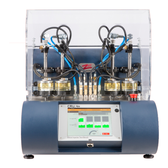
Pump-Injectors 1-by-1 and also use RSP and BIP adapters. This unit uses a Dynamic Mass Metering system and can do Coding on select injectors. Front View Figure: CRU.4R Diesel Injector (Not included) Injector Harness Cables Injector Clamp / Discharge Height Adjuster (iPSC mounted) with LED... -
Page 13: Cru.2R
Operation Manual – “R” Units CRU.2R Intended Use This unit can automatically and fully Test and Clean up to 1 Common Rail Injector simultaneously. It has the capability to fit SPR and RSP adapters on Common Rail injectors. In addition, it supports EUI (UIPR-A) and HEUI (HUIR-A) Attachment units, that can perform testing of these Pump-Injectors 1-by-1 and also use RSP and BIP adapters. -
Page 14: Gdu.4R
Operation Manual – “R” Units GDU.4R Intended Use This unit can automatically and fully Test up to 4 HP Gasoline Direct Injectors simultaneously. It has the capability to fit SPR and RSP adapters on Common Rail injectors. This unit uses a Dynamic Mass Metering system. Front View Figure: GDU.4R Gasoline Injector (Not included) -
Page 15: Gdu.2R
Operation Manual – “R” Units GDU.2R Intended Use This unit can automatically and fully Test and Clean up to 1 HP Gasoline Direct Injector. It has the capability to fit SPR and RSP adapters on Common Rail injectors. This unit uses a Dynamic Mass Metering system. -
Page 16: Ds-R
Operation Manual – “R” Units DS-R Intended Use This unit can fully Test and Clean up to 1 Common Rail Injector. It has the capability to fit SPR and RSP adapters on Common Rail injector. In addition, it supports EUI (UIPR-A) and HEUI (HUIR-A) Attachment units, that can perform testing of these Pump-Injectors 1-by-1 and also use RSP and BIP adapters. -
Page 17: Dsf-R
Operation Manual – “R” Units DSF-R Intended Use This unit can Clean and Flush up to 4 Common Rail Injectors simultaneously. In addition, it supports EUI (UIPR-A) and HEUI (HUIR-A) Attachment units, that can clean/flush these Pump-Injectors 1-by-1. The Unit comes with 2 tanks for cleaning and flushing. -
Page 18: Gd-R
Operation Manual – “R” Units GD-R Intended Use This unit can fully Test and Clean up to 1 HP Gasoline Direct Injector. This unit comes in an automatic (D) & semi-automatic (A) version and uses an Electronic Volumetric Measuring Unit or Volumetric Tube for measuring the injected volume. User intervention is needed in the (A) units to complete the test for adjusting the Test Pressure and Entering the Volumetric Data Front View... -
Page 19: Uip-R
Operation Manual – “R” Units UIP-R Intended Use As an attachment to the main units CRU / DS, or as a standalone unit, it will provide the capability to Test and/or Clean EUI Injectors and Pumps. Front View Figure: UIP-R CAM securing lock Protective Hood Adapter Connections... -
Page 20: Hui-R
Operation Manual – “R” Units HUI-R Intended Use As an attachment to the main units CRU / DS, or as a standalone unit, it will provide the capability to Test and/or Clean HEUI Injectors. Front View Figure: HUI-R Protective Hood Adapter Connections Hydraulic Oil Gauge Hydraulic Oil Adjusting Knob (Adjust on each TP) -
Page 21: Tbcr
Operation Manual – “R” Units TBCR Intended Use This unit, is a Conventional Test Bench Electronic Control & Measurement Unit / Test Bench Simulator for Diesel Specialists It comes in many versions, and the connections and component capability change and are dependent on the specific version. - Page 22 Operation Manual – “R” Units Electrical and Hydraulic Connections Notes: if you don’t have BCR Kit you have to calibrate RDS before use (for further clarifications please contact with our Support Department (e-mail: support@carbonzapp.com)
-
Page 23: Dcd
Operation Manual – “R” Units Intended Use This Control Module, is a CRDi Injector Control Module, Electronic Measurement & Coding device for any Standalone Test Bench It comes in many versions, and the connections and component capability change and are dependent on the specific version. Front View Figure: DCD Control Panel / PC... -
Page 24: Ecmr
Operation Manual – “R” Units ECMR Intended Use This Control Module, is a Test Bench & Component Electronic Control Module for All CRDi, GDi, HEUI Activation Profiles & Data For All Types & Makes / Control & Data / Test Bench Pressure Control Simulator It comes in many versions, and the connections and component capability change and are dependent on the specific version. -
Page 25: Adapters
Operation Manual – “R” Units Adapters Flush-Adapter This is the standard adapter for Discharge of the injector. This adapter is for visually checking the Spray of the injector (different for Gasoline and Diesel Injectors) on every TP, at pressures up to 2500bar. This adapter is optional. MACC feature should not be used with this adapter. -
Page 26: Crin
Operation Manual – “R” Units CRIN Various adapters are available for CRIN (and other side-feed CR Injectors), for adapting on to the machine. These adapters are optional. Various adapters are available for EUI /EUP (Injectors and Pumps), for adapting on to the machine. -
Page 27: Commissioning
Operation Manual – “R” Units Commissioning Installation Once unpacked, install the unit on a steady, leveled bench that can support its weight. Some surrounding space should be free for better ventilation and maintenance. Electrical Connections INFO: Reference the Rating Plate on the rear of the unit, and technical specifications section. - Page 28 Operation Manual – “R” Units...
-
Page 29: Filling The Tanks
Operation Manual – “R” Units Filling the Tanks All Tank ports are marked according to the type of fluid: MACC: For Cleaning fluid (MACC Function) TEST: For Calibration Test Oil TEST.OIL: For Hydraulic High Pressure Oil (HEUI System), use ISO 4113 The procedure is the same for all types of Fluids: 1. -
Page 30: Tank Level Sensors
Operation Manual – “R” Units Tank Level Sensors In addition to the external level indicators, the units are also equipped with electronic level sensors. In case the Test Oil level is low or the Cleaning (MACC) fluid level is High, the unit will STOP operation and popup a screen message. -
Page 31: Filling The Spray Chamber
Operation Manual – “R” Units Filling the Spray Chamber IMPORTANT: Only use Calibration Testing Oil with the spray chamber. Use a Funnel to poor Calibration Testing Oil into the Spray Chamber. The Chamber should be as air free as possible. Once the Spray Chamber is filled for the first time, it is necessary inject oil from an injector for at least 2 minutes at a rich TP in order to eliminate any air pockets and to maximize the efficiency of the measuring unit. -
Page 32: Printer Setup
Operation Manual – “R” Units 4. Getting Instant support (Via TeamViewer) 5. Sending Report by Email Steps on how to connect to a WIFI Network: 1. Switch On the machine 2. Power ON the PC (Hold the Power button unit the Manufacturer logo appears) 3. -
Page 33: Connection To The Pcb / Demo Mode
Operation Manual – “R” Units Connection to the PCB / DEMO Mode The Software “AZO” is designed to run in DEMO Mode whenever there is no connection to the PCB Board or there is loss of power. Once power and connection is restored, the software will restart automatically. -
Page 34: Software Orientation
Operation Manual – “R” Units Software Orientation HOME... -
Page 35: User Logins
Operation Manual – “R” Units User Logins: CRU/GDU/MTBR/TBCR Guest >> Logs in with basic rights. Username: user / Password: user1111 (Single Page Report) Username: developer / Password: dev1011 (Multi Page Report) DS/GD/DCDR/ECMR (duplicate / edit / oscilloscope) Username: suser / Password: su (Single Page Report) ... -
Page 36: Settings
Operation Manual – “R” Units SETTINGS From the Settings screen, the user can edit the personal information of the machine, connect to a WiFi network, change the locale of the machine, backup/restore personal info, and other service settings. Logo Display Photo (max 100KB) INJECTOR/COMPONENT SELECTION The user can either scroll through the components, or just search. -
Page 37: Customer Data
Operation Manual – “R” Units CUSTOMER DATA A screen to provide a point to enter the info of the client. COMPONENT DATA Once the required slots have been selected (multi Slot machines), it is mandatory to enter the Serial Number of the component, since this is the unique identification. Further, the user can also enter other info like Fabrication Data and/or existing Coding of the component. -
Page 38: Cfl 1/2/3
Operation Manual – “R” Units CFL 1/2/3 The Connection / Leaks screen, help the user with 3 steps to assure the following: 1. Correct connections 2. Component is capable of testing and it is not damaged severely 3. Machine is capable to test the component Specifically, Step 1/3 applies a low pressure in order to diagnose basic, immediate leaks. -
Page 39: Adjust Hp
Operation Manual – “R” Units ADJUST HP In some machines, some options are not automatic, and therefore the user is responsible to adjusting the required pressure and/or feature to the TP. -
Page 40: Eui
Operation Manual – “R” Units Some machines also have an RPM Meter (by proximity sensor), or Low Pressure hydraulic system. For the LP, no sensor is available, rather a Percentile of the maximum capacity, which is 10bar usually. -
Page 41: Select Tests
Operation Manual – “R” Units SELECT TESTS In this screen, the user can select which Tests to perform. In addition, the user is informed if the MACC will also perform. Consider unselecting RSP and NOP if there is no RSP Adapter installed. From the Options Button, the user can select to enter Manual Mode. -
Page 42: Macc
Operation Manual – “R” Units MACC For about 15 minutes, the component(s) will Clean with MACC. After this process, the component and lines will automatically Flush with Test Oil, while wasting this Oil in the MACC Tank. During MACC test you need Flush adapter and when the test is finished you need to remove the Flush adapter and you have to use RSP Sensor or iPSC Chamber. - Page 43 Operation Manual – “R” Units REVERSE Backflush (only for GD and GDU series) ...
-
Page 44: Test (###)
Operation Manual – “R” Units TEST (###) Change to Manual mode as shown on the photo Change to Quick test then click as shown on the photo (only for DS1R/DCDR/GD1R) The Test screen is specific for each test, showing the Tanks for each Slot and Measurement, units and time of test. - Page 45 Operation Manual – “R” Units By pressing the Test List button, a List of the tests will be shown. By Long Pressing a Test with results, a Quick Report will be displayed. When stopped, by pressing a test from the list, it will repeat it and/or jump directly to it by skipping the in between tests.
-
Page 46: Reports
Operation Manual – “R” Units Once all the tests are finished, the software will ask to create a report or not. If in Manual mode, this will never be displayed. REPORTS... -
Page 47: Report Versions
Operation Manual – “R” Units When a Test cycle ends, or directly from HOME >> Reports, the user can access the system saved reports. There are 3 options once a Report is selected: Save to USB: A USB Drive need to be connected to the system. A PDF is saved on ... -
Page 48: Share
Operation Manual – “R” Units SHARE... -
Page 49: Save To Usb
Operation Manual – “R” Units Save to USB... -
Page 50: Operation
Operation Manual – “R” Units Operation Before Testing Power On the unit and the PC. Use Ultrasonic Bath to clean the Injectors and/or Components thoroughly before installing on the machines. IMPORTANT: FAILURE to clean the component before installing on the machine, could contaminate the hydraulic system and most probably fail the measuring unit, DRV Pressure Control or even the Solenoid Valves. - Page 51 Operation Manual – “R” Units INFO: When MACC is selected, the machine will automatically perform MACC (apprx. 15 min), Flush the lines and component (approx. 1 min), and then start testing of the component automatically. A complete test varies depending on machine and component, but can be estimated from 10-30 minutes.
-
Page 52: Results And Reports
Operation Manual – “R” Units When creating a report, all reports are saved in the system The user can either save the report on a USB drive, or Share via various system options, like: i. Gmail ii. Dropbox iii. -
Page 53: Maintenance
Operation Manual – “R” Units Maintenance Regular Maintenance Check for Machine Leaks daily Check the Hoses and Cables for raptures or wear. Replace after 2 years or when not in good condition Change Filter and Fluids (after replace go to settings machine to reset time of ... - Page 54 Operation Manual – “R” Units D & R Port RDS Calibration Log in as service (username: service password: 12345) >> Go to 3Dots >> Settings >> Machine >> Service Machine >> Select Calibrate RDS (Connect ONLY HP Gauge 2000bar) Note: DCDS &...
-
Page 55: Troubleshooting
Operation Manual – “R” Units Troubleshooting Component Problem Solution Not Booting Assure Machine is plugged in a power source and turned on. Switch the unit on/off Touch not working Reboot the system (power on/off) Pressure Cannot Reach TP Pressure Assure there is enough ... -
Page 56: Technical Specifications
Operation Manual – “R” Units Technical Specifications CRU.4R Mains Supply 100-240 VAC / 1P / 50-60Hz (+/- 10%) Compressed Air 6.5-10.0 bar / 650lt/min Compressed Air Hose <10m long / Internal Diameter >10mm Rated Current / Fuse Rated Power 300 Watt... - Page 57 Operation Manual – “R” Units DS-R Mains Supply 100-240 VAC / 1P / 50-60Hz (+/- 10%) Compressed Air 7.5-10.0 bar / 400lt/min Compressed Air Hose <10m long / Internal Diameter >10mm Rated Current / Fuse Rated Power 300 Watt Storage Temperature C - +60 Operating Temperature C - +45...
- Page 58 Operation Manual – “R” Units GDU.4R Mains Supply 100-240 VAC / 1P / 50-60Hz (+/- 10%) Compressed Air 6.5-10.0 bar / 650lt/min Compressed Air Hose <10m long / Internal Diameter >10mm Rated Current / Fuse Rated Power 300 Watt Storage Temperature C - +60 Operating Temperature C - +45...
- Page 59 Operation Manual – “R” Units GD-R Mains Supply 100-240 VAC / 1P / 50-60Hz (+/- 10%) Compressed Air 7.5-10.0 bar / 400lt/min Compressed Air Hose <10m long / Internal Diameter >10mm Rated Current / Fuse Rated Power 300 Watt Storage Temperature C - +60 Operating Temperature C - +45...
- Page 60 Operation Manual – “R” Units UIPr Compressed Air 6.5-10.0 bar / 300lt/min Compressed Air Hose <10m long / Internal Diameter >10mm Storage Temperature C - +60 Operating Temperature C - +45 Normal Operating Temperature C - +40 Max Pressure (bar) Tightening Torque for High Pressure 25 - 30 Nm Connections...
- Page 61 Operation Manual – “R” Units DCDR Mains Supply 100-240 VAC / 1P / 50-60Hz (+/- 10%) Rated Current / Fuse Rated Power 300 Watt Storage Temperature C - +60 Operating Temperature C - +45 Normal Operating Temperature C - +40 Dimensions (W x D x H) / Weight 35 x 48 x 34 cm / 14kg ECMR...
Need help?
Do you have a question about the CRU.4R and is the answer not in the manual?
Questions and answers