Table of Contents
Advertisement
Quick Links
Advertisement
Table of Contents

Related Manuals for Jung 4074 TSM


Summary of Contents for Jung 4074 TSM
- Page 1 Product documentation Standard push-button module with BCU, 4-gang Art.-No.: 4074 TSM ALBRECHT JUNG GMBH & CO. KG Volmestraße 1 D-58579 Schalksmühle Telefon: +49.23 55.8 06-0 Telefax: +49.23 55.8 06-1 89 E-mail: mail.info@jung.de Internet: www.jung.de www.jung-katalog.de Issue: 02.09.2008...
-
Page 2: Table Of Contents
4.4.2 Object table ......................4.4.3 Parameters ......................4.5 Software "Value transmitter, scene extension 109Bx4" ..........4.5.1 Scope of functions ....................4.5.2 Object table ......................4.5.3 Parameters ......................5 Appendix ..........................5.1 Index ..........................Art.-No.: 4074 TSM Page 2 of 32... -
Page 3: Product Definition
0.75 Hz and the push button sensor does not work. A BCU is already permanently integrated in the Standard TSM push button sensor, allowing the device to be connected directly to the bus cable during commissioning. Art.-No.: 4074 TSM Page 3 of 32... -
Page 4: Installation, Electrical Connection And Operation
During installation, adequate insulation between the mains voltage and the bus must be ensured! A minimum distance of at least 4 mm must be maintained between bus con- ductors and mains voltage cores. The device may not be opened or operated outside the technical specifications. Art.-No.: 4074 TSM Page 4 of 32... -
Page 5: Device Components
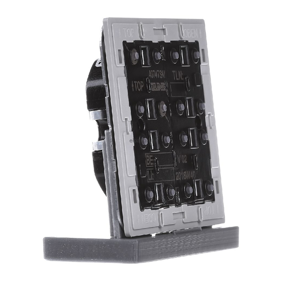
(3) 1 operation LED (blue) Dimensions of the Standard TSM push button sensor: Width (W): 55 mm / Height (H): 55 mm / Depth (D): 20 mm Dimensions without decorative frame and covers, without supporting plate. Art.-No.: 4074 TSM Page 5 of 32... -
Page 6: Fitting And Electrical Connection
Installing the push button sensor and connecting it picture 2: Installation of the push button sensor (4) Supporting ring (5) Decorative frame (6) Adapter frame (only for the CD design) (7) Push button module (8) Fastening screws Art.-No.: 4074 TSM Page 6 of 32... - Page 7 Fasten the push button module (7) to supporting ring using the supplied plastic screws (8). Tighten the plastic screws only lightly. Before mounting the control surfaces (9), load the physical address into the device (see chapter 2.4. Commissioning). Art.-No.: 4074 TSM Page 7 of 32...
-
Page 8: Commissioning
The telegram transmitted depends on the but- ton function programmed. Art.-No.: 4074 TSM Page 8 of 32... - Page 9 To simplify installation, a complete set of buttons is fitted with a mounting spider at the fact- ory. This mounting spider is not essential for installing the decorative control surfaces, meaning that it is not required when adding symbol buttons to the button panel. Art.-No.: 4074 TSM Page 9 of 32...
-
Page 10: Operation
The operation LED of the push button sensor can be switched permanently on or off. Besides functions programmed in the ETS, the operation LED also indicates that the push button sensor is in Programming mode for commissioning or diagnosis purposes. Art.-No.: 4074 TSM Page 10 of 32... -
Page 11: Technical Data
-25 ... +70 °C KNX / EIB supply KNX medium TP 1 Commissioning mode S mode Rated voltage KNX DC 21 V ... 32 V SELV Power consumption KNX typ. 150 mW Connection mode KNX Terminal Art.-No.: 4074 TSM Page 11 of 32... -
Page 12: Software Description
Version d Touch sensor application to send value Value transmitter, or scene telegrams. scene extension for ETS 2 109B04 and ETS 3.0a…c Value transmitter, from ETS 3 scene extension from 109B14 Version d Art.-No.: 4074 TSM Page 12 of 32... -
Page 13: Software "Switching 109Bx1
Scope of functions 4.2 Software "Switching 109Bx1" 4.2.1 Scope of functions Scope of functions Function of operation LED and status LED configurable Rocker or button function. Command on actuating the buttons configurable (ON, OFF, TOGGLE). Art.-No.: 4074 TSM Page 13 of 32... -
Page 14: Object Table
Objects for button function: Function: Switching Object Function Name Type DP type Flag Switching Button 1 1 bit 1.xxx C, W, T Description 1-bit object for the transmission of switching telegrams (ON, OFF). Art.-No.: 4074 TSM Page 14 of 32... - Page 15 1-bit object for the transmission of switching telegrams (ON, OFF). Function: Switching Object Function Name Type DP type Flag Switching Button 8 1 bit 1.xxx C, W, T Description 1-bit object for the transmission of switching telegrams (ON, OFF). Art.-No.: 4074 TSM Page 15 of 32...
-
Page 16: Parameters
Always ON Button-press indicator Status display (of the switching object 0) Inverted status display (of the switching display 0) Status display (of the switching object 1) Inverted status display (of the switching display 1) Art.-No.: 4074 TSM Page 16 of 32... - Page 17 Only for button function. TOGGLE Command on releasing No function Defines the command on releasing the the bottom button bottom button. i Only for button function. TOGGLE h For rocker 2...4 see rocker 1. Art.-No.: 4074 TSM Page 17 of 32...
-
Page 18: Software "Dimming 109Bx2
Scope of functions Function of operation LED and status LED configurable Rocker function Command on actuating the rocker configurable (lighter - ON, darker - OFF). Time between switching and dimming can be set. Art.-No.: 4074 TSM Page 18 of 32... -
Page 19: Object Table
4-bit object for relative brightness adjustment between 0% and 100 %. Function: Dimming Object Function Name Type DP type Flag Dimming Rocker 2 4 bit 3.007 C, W, T Description 4-bit object for relative brightness adjustment between 0% and 100 %. Art.-No.: 4074 TSM Page 19 of 32... - Page 20 4-bit object for relative brightness adjustment between 0% and 100 %. Function: Dimming Object Function Name Type DP type Flag Dimming Rocker 4 4 bit 3.007 C, W, T Description 4-bit object for relative brightness adjustment between 0% and 100 %. Art.-No.: 4074 TSM Page 20 of 32...
-
Page 21: Parameters
Time between switching 0.3 s Defines the time between between a and dimming 0.4 s switching and a dimming telegram. 0.5 s 0.7 s 1.0 s h For rocker 2...4 see rocker 1. Art.-No.: 4074 TSM Page 21 of 32... -
Page 22: Software "Blind 109Bx3
4.4.1 Scope of functions Scope of functions Function of operation LED and status LED configurable Rocker function Command on actuating the rocker configurable (UP, DOWN). Time between short-time and long-time commands can be set. Art.-No.: 4074 TSM Page 22 of 32... -
Page 23: Object Table
1-bit object for long-time operation of a blind or roller shutter. Function: Blind Object Function Name Type DP type Flag Long-time operation Rocker 2 1 bit 1.008 C, -, T Description 1-bit object for long-time operation of a blind or roller shutter. Art.-No.: 4074 TSM Page 23 of 32... - Page 24 1-bit object for long-time operation of a blind or roller shutter. Function: Blind Object Function Name Type DP type Flag Long-time operation Rocker 4 1 bit 1.008 C, -, T Description 1-bit object for long-time operation of a blind or roller shutter. Art.-No.: 4074 TSM Page 24 of 32...
-
Page 25: Parameters
Time between the short- 0.3 s Defines the time between a short-time time and long-time com- 0.4 s and a long-time telegram. mand 0.5 s 0.7 s 1.0 s h For rocker 2...4 see rocker 1. Art.-No.: 4074 TSM Page 25 of 32... -
Page 26: Software "Value Transmitter, Scene Extension 109Bx4
4.5 Software "Value transmitter, scene extension 109Bx4" 4.5.1 Scope of functions Scope of functions Function of operation LED and status LED configurable. Rocker function Command on pressing the rocker configurable (values 0...255 / 0...100 % or scene num- bers). Art.-No.: 4074 TSM Page 26 of 32... -
Page 27: Object Table
Objects for the "Scene extension" function: Function: Scene extension Object Function Name Type DP type Flag Scene extension Rocker 1 18.001 C, -, T byte Description 1-byte object for recalling or for storing a scene. Art.-No.: 4074 TSM Page 27 of 32... - Page 28 1-byte object for recalling or for storing a scene. Function: Scene extension Object Function Name Type DP type Flag Scene extension Rocker 4 18.001 C, -, T byte Description 1-byte object for recalling or for storing a scene. Art.-No.: 4074 TSM Page 28 of 32...
-
Page 29: Parameters
Only for "Command on pressing the rocker = Value transmitter 0...255"! Value top rocker 0...100 Defines the value when the rocker but- (0…100 %) ton is pressed up. Art.-No.: 4074 TSM Page 29 of 32... - Page 30 Defines the scene number when the er (1...64) rocker button is pressed up. Scene number bottom 1...2...64 Defines the scene number when the rocker (1...64) rocker button is pressed down. h For rocker 2...4 see rocker 1. Art.-No.: 4074 TSM Page 30 of 32...
-
Page 31: Appendix
Control surfaces ........10 ETS search paths: ........12 Fitting the control surfaces ....... 9 Installation ..........6 Snapping on the adapter frame ....6 Structure of the device ......5 Art.-No.: 4074 TSM Page 31 of 32... - Page 32 Appendix ALBRECHT JUNG GMBH & CO. KG Volmestraße 1 D-58579 Schalksmühle Telefon: +49.23 55.8 06-0 Telefax: +49.23 55.8 06-1 89 E-mail: mail.info@jung.de Internet: www.jung.de www.jung-katalog.de Art.-No.: 4074 TSM Page 32 of 32...
Need help?
Do you have a question about the 4074 TSM and is the answer not in the manual?
Questions and answers