Table of Contents
Advertisement
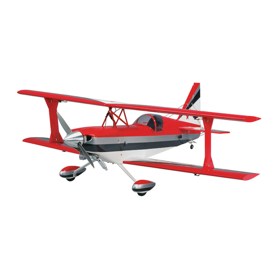
The Ultimate ARF
INSTRUCTIONS
Welcome to the world of Ultimate flying! Now that you're an experienced R/C pilot, you're ready to step up to
a higher level of aerobatic flying. And we've made sure this ARF version won't disappoint. With just the same
flight characteristics as the kitted version, you'll soon know why the Carl Goldberg Products Ultimate has
been America's favorite sport biplane since 1990.
A radio-controlled model is not a toy and is not intended for persons under 16 years old. Keep
this kit out of the reach of younger children, as it contains parts that could be dangerous. A radio-
controlled model is capable of causing serious bodily injury and property damage. It is the buyer's
responsibility to assemble this aircraft correctly and to properly install the motor, radio, and all other
equipment. Test and fly the finished model only in the presence and with the assistance of another
experienced R/C flyer. The model must always be operated and flown using great care and common
sense, as well as in accordance with the Safety Code of the Academy of Model Aeronautics
(www.modelaircraft.org). We suggest you join the AMA and become properly insured prior to flying this
model. Also, consult with the AMA or your local hobby dealer to find an experienced instructor in your
area. Per the Federal Communications Commission, you are required to use only those radio fre-
quencies specified "for Model Aircraft."
Carl Goldberg Products, Ltd. has inspected and certified the components of this aircraft. The company urges the buyer to per-
form his own inspection, prior to assembly, and to immediately request a replacement of any parts he believes to be defective for
their intended use. The company warrants replacement of any such components, provided the buyer requests such replacement
within a period of 90 days from the date of purchase and provided the defective part is returned, if so requested by the company.
No other warranty, expressed or implied, is made by the company with respect to this kit. The buyer acknowledges and under-
stands that it is his responsibility to carefully assemble the finished flying model airplane and to fly it safely. The buyer hereby
assumes full responsibility for the risk and all liability for personal or property damage or injury arising out of the buyer's use of
the components of this kit.
CARL GOLDBERG PRODUCTS, LTD.
P.O. Box 818 Oakwood GA 30566 Phone #678-450-0085 Fax # 770-532-2163 www.carlgoldbergproducts.com
© Copyright 2000 Carl Goldberg Products LTD.
WARNING
LIMITED WARRANTY
1
PT. #2045 6/03
Advertisement
Table of Contents

Related Manuals for Carl Goldberg Products ULTIMATE


Summary of Contents for Carl Goldberg Products ULTIMATE
- Page 1 INSTRUCTIONS Welcome to the world of Ultimate flying! Now that you're an experienced R/C pilot, you're ready to step up to a higher level of aerobatic flying. And we've made sure this ARF version won't disappoint. With just the same flight characteristics as the kitted version, you'll soon know why the Carl Goldberg Products Ultimate has been America's favorite sport biplane since 1990.
- Page 2 PILOT FIGURE 30-60-90° x 6" TRIANGLE SWITCH HARNESS SOFT PENCIL A FEW STRAIGHT OR "T" PINS NOTE: The Ultimate ARF covering matiches ADJUSTABLE WRENCH Bright Yellow(#872), Deep Blue(#873) UltraCote ® . WIRE CUTTER (DYKES) UltraCote ® is a registered trademark of Horizon Hobby Distributors...
-
Page 3: Preparing For Assembly
Goldberg Models via e-mail (questions@carlgoldberg- products.com) or by telephone 1-678-532-0085. COVERING The Ultimate ARF is covered in genuine a premium poly- ester film chosen by many of the world's top flyers for its beauty, toughness, and ease of application and repair. It is not uncommon for ARF's to develop a few wrinkles in transit. -
Page 4: Wing Construction
WING CONSTRUCTION When satisfied with the alignment, remove Aileron Installation the straight pins, being sure to keep the aileron tight to the wing. You may wish to Collect the following parts: apply a few pieces of masking tape to keep (1) Top Wing the pieces in place. - Page 5 With the servo door upside down on the Hold one of the servo plates in place against work surface, place the servo on top of the one corner of the servo door, locating it in door with the servo arm post centered verti- such a way that the tab does not interfere cally and horizontally with the servo door with the servo.
-
Page 6: Control Horn Installation
Aileron Extension Installation Grasping the string in the hole in the center Gather the following items. of the wing, SLOWLY pull until the end of the (2) 12” extension wires 12” extension comes out of the hole. Work the string back and forth to get the extension NOTE: Before starting, remove the servo door and plug to go through the cutouts in each rib. -
Page 7: Wing Dowel Installation
Wing Dowel Installation Using epoxy, mount the 5/16 x 1-3/4” dowels Position the control horn so that the snap into the holes in the leading edge of the bot- link holes are right next to the hinge line. tom wing. Make sure to leave about 1/2” of dowel sticking out of the front of the wing. -
Page 8: Fuselage Assembly
FUSELAGE ASSEMBLY Cabane Installation Beginning at the front of the fuselage, make a mark at 5” and at 9-3/4”. This will help locate the pre-cut cabane slots on the curved top of the fuse, behind the firewall. Collect the following parts. (1) Fuselage (1) Servo tray (2) Front cabane doubler... -
Page 9: Stabilizer/Fin Installation
Stabilizer/Fin Installation Turn the fuselage over and, working from the inside, insert a 4-40 x 1/2” screw with a #4 x 7/16” washer into the fuselage hole in the cabane doubler and then through the cabane hole. This is somewhat tricky, so have patience. - Page 10 Locate the pre-cut stab cutout by feeling along the fuse side in the area where the Turn the fuse around, and determine the stab should go. vertical centerline of the fuse top front. Measure to the center point on the top of the Remove the covering over the stab slot on fuselage.
- Page 11 Locate the solid wood area under the cover- When the stab is correctly aligned, outline on ing and place marks on the line where the both the top and bottom of the stab where it wood ends. Make sure not to mark any open meets the fuse, as shown.
-
Page 12: Elevator/Rudder Hinge Installation
When dry, turn the fuse over and wick a few On the elevator, mark the location of the drops of thin CA gluet along the stab/fuse mounting holes on the base of the control joint. horn and drill, using a 3/32” bit. Then mount the control horn as shown, using 2-56 x 3/4”... -
Page 13: Landing Gear Installation
Take three hinges and, as with the aileron Landing Gear Installation hinge installation, insert the hinge into the elevator, using straight pins to ensure the hinge stays centered between the stabilizer and the elevator. Slide the exposed side of the hinge into the slots in the stab until the pins touch both the stab and the elevator. -
Page 14: Tail Wheel Installation
One of the bracket collars has two holes Tailwheel Installation threaded into it, one on each side. This one is the top one. Put the bottom bracket collar on the axle and insert it through the spring bracket. Put the top collar bracket on top and tight- ened the two set screws. -
Page 15: Elevator Servo Installation
REMEMBER, the following pictures and instruc- tions may vary slightly, depending on the equipment you are using. Align Marks Place the engine on the motor mount, mak- ing sure the propeller drive plate is 5-5/8” away from the firewall. Using the alignment marks, center the motor mount on the firewall and tack glue. -
Page 16: Elevator Pushrod Installation
Elevator Pushrod Installation Using the 5/64” drill, and holding a pushrod Collect the following items: plug, as shown, drill out the center of the plug to form a tube. Repeat for the other plug. (3) .072 x 10” threaded wire (3) Nylon snap link (1) Single-hole pushrod plug (1) Double-hole pushrod plug... - Page 17 When the bent tip is exiting the hole in the pushrod and the plug tightly meets the pushrod, apply CA glue to the joint. With the pointed end of the plug facing the threaded end of the wired, slide the double- hole plug onto the non-threaded end of the wires.
-
Page 18: Rudder Cable Installation
Thread the snap-links onto each of the wires, until the the wire shows in the middle of the snap-link. Connect the snap-link to the second hole of control horn. Using flux and silver solder, solder a thread- ed coupler onto the end of the cable. From the coupler end, and including the cou- pler itself, measure 30 inches and mark the cable. - Page 19 Make sure the cables are tight and that the rudder does not move without moving the servo. NOTE: This servo works best if it has ball bearings. Canopy & Cockpit Installation Collect the following items: (1) Cockpit insert (1) Canopy (4) #2 x 3/8”...
- Page 20 Mark 1/4” from the end of the .063 wire and make a 90º bend. Cut the wire to a length of 12-3/8”. Holding the engine in your hand, take the Cut off a piece of nylon guide tube 9-1/2” bent end of the .063 wire and place it on the long.
-
Page 21: Cowl Installation
Slide the cowl under the plastic. Cowl Installation CAUTION! WHEN CUTTING THE COWL, ALWAYS 1. Collect the following items: WEAR PROTECTIVE EYE GEAR AND A LONG- (1) Fiberglass cowl SLEEVE SHIRT. CHANGE CLOTHES AND WASH (4) #4 x 3/8 sheet metal screws AFTER CUTTING. -
Page 22: Fuel Tank Installation
Fuel Tank Installation Place a piece of masking tape down the cen- ter of the wide yellow trim stripe. Measuring up 1-3/8” from the bottom of the yellow stripe, make two marks and draw a line on the tape, parallel to the yellow stripe. Make a third mark on the tape, even with the Collect the following items: back of the landing gear. - Page 23 Referring to the above photo, place the fuel Bend the other tube, at the angle shown, tank on the fuel tank platform. until it nearly reaches to the fuel tank wall. This is the vent/overflow tube. Secure the tank to the platform with the rub- ber bands.
-
Page 24: Receiver Installation
Reach into the fuselage and place the fuel tubing onto the brass fuel tank tubes. Note Plug the switch into both the battery and the which tube is the vent and which is the outlet. receiver. From the front of the firewall, pull on the fuel Next, plug the elevator, rudder, and throttle lines to remove any slack. - Page 25 Insert the threaded part of the axle through When satisfied with the fit of all the compo- both sides of the landing gear and tighten nents, mount the wheelpants, wheels and the locking nut on each axle. the remaining (outside) wheel collars onto the axle.
- Page 26 FINAL WING INSTALLATION Wing/I-strut Installation Collect the following items: (1) Bottom wing (1) Top wing (1) Bottom wing bolt plate (2) I-struts (8) 4-40 x 1/2” sock head screw (8) 4-40 blind nut (8) #4 washer (1) 6-32 x 1” socket head screw (1) 6-32 blind nut Working from inside of the fuselage wing (1) #6 x 3/34”...
- Page 27 Aileron Coupler Installation Collect the following items: (4) Small control horn (8) 2-56 x 1/2” pan head machine screw (2) .072 x 10-1/2” double threaded wire (4) Mini snap link Working from the outside (towards the fuse- lage) insert the 4-40 x 1/2” socket head screws with #4 washers through the holes in the I-strut.
-
Page 28: Decal Installation
Spinner Assembly A 3" CGP 4-Pin Snap-On Spinner is included with your Ultimate ARF. It is a rugged precision molded spinner that does not require any special mounting nuts or screws. CAREFULLY READ THE SPINNER INSTRUCTIONS AND WARNINGS INCLUDED WITH THE SPINNER. - Page 29 Radio transmitter Take-Off & Landing 1 ½ volt starting battery & glo-plug clip Though the ULTIMATE is not difficult to control dur- Fuel bulb or pump ing take-off and landing, it is important to not over- Tools for tightening any parts that can vibrate control.
-
Page 30: Advanced Aerobatics
ADVANCED AEROBATICS Developing your flying skills to include more varied maneuvers is exciting and rewarding.. The ULTI- MATE is an extremely capable aircraft and is able to do advanced stunts. Here are a few you might try. KNIFE-EDGE LOOP This maneuver requires a powerful engine Roll to the left or right and hold a bit (10%) of top rudder.
Need help?
Do you have a question about the ULTIMATE and is the answer not in the manual?
Questions and answers