Table of Contents
Advertisement
Quick Links
Advertisement
Table of Contents

Subscribe to Our Youtube Channel
Related Manuals for mikroElektronika Ready for PIC MIKROE-766


Summary of Contents for mikroElektronika Ready for PIC MIKROE-766
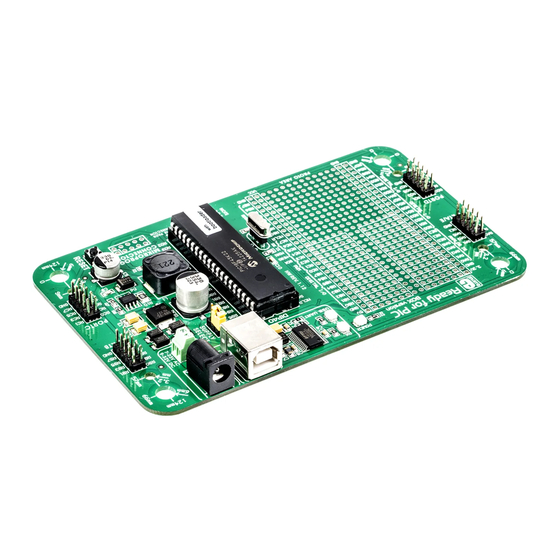
- Page 1 Ready with for PIC ® ™ DIP40 socket Best solution for fast and simple development of applications using 40-pin PIC MCUs. Due ® to the special white plastic casing the Ready for PIC board can be quickly ® turned into a final product. Arrow.com.
- Page 2 TO OUR VALUED CUSTOMERS I want to express my thanks to you for being interested in our products and for having confidence in MikroElektronika. The primary aim of our company is to design and produce high quality electronic products and to constantly improve the performance thereof in order to better suit your needs.
-
Page 3: Table Of Contents
Table of contents Introduction step 5 – Uploading .HEX file Package contains step 6 – Progress bar Key features step 7 – Finishing upload 1. Power supply 3. Programming with mikroProg programmer 15 ™ 2. Programming with mikroBootloader 4. USB-UART mikroBootloader software 5. -
Page 4: Introduction
Introduction Ready for PIC Board is the best solution ® for fast and simple development of various microcontroller applications. The board is equipped with the PIC18F45K22 MCU that is placed in a DIP 40 socket and contains male headers and connection pads for all available microcontroller ports. -
Page 5: Package Contains
Package contains Damage resistant protective box Ready for PIC board ® User’s guide and schematics USB cable, one 2x5 header Page 5 Arrow.com. Arrow.com. Arrow.com. Arrow.com. Arrow.com. Downloaded from Downloaded from Downloaded from Downloaded from Downloaded from... -
Page 6: Key Features
Key features System specification Power LED indicator power supply UART communication LEDs (RX.TX) Via AC/DC connector 7-23V AC FTDI chip or 9-32V DC USB UART connector Power supply select power consumption Power adapter connector 6.2mA in idle state Power screw terminals (when on-board modules are off) Male headers Reset button... - Page 7 Page 7 Arrow.com. Arrow.com. Arrow.com. Arrow.com. Arrow.com. Arrow.com. Arrow.com. Downloaded from Downloaded from Downloaded from Downloaded from Downloaded from Downloaded from Downloaded from...
-
Page 8: Power Supply
1. Power supply Figure 1-1: Figure 1-2: Figure 1-3: USB power supply AC/DC adapter power supply screw terminals power supply Ready for PIC board can be powered in three different ways: via USB connector (CN1), via adapter connector using external adapters (CN2) or ®... - Page 9 REG1 VCC- 5V VCC- USB VCC- 5V VCC- 3.3V Vout VCC- 5V MC33269DT3.3 10uF MBRS140T3 10uF POWER FERRI TE 3.3V VOLTAGE REGULATOR USB B 100nF VCC- 3.3 VCC- 5V VCC- 5V DRVC 0.22 220uH 1N4007 1N4007 VCC-EXT CMPR 330uF/35V VCC- 5V MBRS140T3 CN46 220pF...
-
Page 10: Programming With Mikrobootloader
2. Programming with mikroBootloader mikroBootloader software You can program the microcontroller with the bootloader that is preprogrammed into the device by default. To transfer .hex note file from a PC to the MCU you need the bootloader software Before starting mikroBootloader, connect Ready for PIC to a ®... -
Page 11: Identifying Device Com Port
Identifying device COM port step 1 – Choosing COM port Figure 2-2: Identifying COM port Figure 2-3: Choosing COM port Open Device Manager window and expand Click the Change Settings button Ports section to see which COM port is assigned From the drop down list, select appropriate COM to Ready for PIC board (in this case it is COM3) -
Page 12: Step 2 - Establishing Connection
step 2 - Establishing connection step 3 - Browsing for .HEX file Figure 2-4: Connecting with mikroBootloader Figure 2-5: Browse for HEX Press the Reset button on the Ready for PIC board Click the Browse for HEX button and from a ®... -
Page 13: Step 4 - Selecting .Hex File
step 4 - Selecting .HEX file step 5 - Uploading .HEX file Figure 2-6: Locating and selecting .hex file Figure 2-7: Begin uploading Select the .HEX file using the Open dialog win- To start .HEX file bootloading click the Begin uploading button Click Open Page 13 Arrow.com. -
Page 14: Step 6 - Progress Bar
step 6 - Progress bar step 7 - Finishing upload Figure 2-8: Progress bar Figure 2-9: Restarting MCU Click OK after the uploading process is finished You can monitor .HEX file uploading via progress bar Press the Reset button on the Ready for PIC ®... -
Page 15: Programming With Mikroprog ™ Programmer
3. Programming with mikroProg programmer ™ The board is equipped with mikroProg connector pads, ™ which allow you to program the microcontroller using external mikroProg programmer. Before attaching the ™ programming connector, it is necessary to make a few adjustments (Page 16). Figure 3-1: mikroProg ™... - Page 16 Figure 3-2: cutting copper Figure 3-3: placing 2x5 Figure 3-4: soldering 2x5 Figure 3-5: Connecting between pads male header male header on the pads mikroProg programmer ™ First you need to cut the copper between pads for the external programmer, Figure 3-2. By doing so pins RB6, RB7, MCLR and VCC on the MCU will be separated from the rest of the board.
- Page 17 DIP 40 VCC- MCU VCC- MCU MCLR-MCU RB7-MCU RB6-MCU VCC- MCU 22pF OSC1 8 MHz RB6-MCU OSC2 RB7-MCU 22pF MCLR-MCU MCLR mikroProg VCC- MCU VCC- MCU CONNECTOR 100nF 100nF Figure 3-6: mikroProg programmer connection schematic ™ Page 17 Arrow.com. Arrow.com. Arrow.com.
-
Page 18: Usb-Uart
4. USB-UART Fast on-board FTDI chip allows Ready for PIC to communicate ® ® with a PC or other UART devices using a USB-UART connection. USB-B connector (CN1) is used for connecting the USB cable. RX (receive) and TX (transmit) LEDs will indicate communication status. Before connecting the board to a PC, make sure that you have the appropriate FTDI drivers installed on your operating system. -
Page 19: Prototyping Area
5. Prototyping area DATA BUS Figure 5-2: GREEN YELLOW schematic of three LEDs connected to microcontroller pins as shown in Figure 5-1 Proto area allows you to expand your Ready for PIC board with ® additional functionality. It can be done by placing your additional components on the available prototyping area. -
Page 20: Pin Headers And Connection Pads
6. Pin headers and connection pads Each microcontroller pin is available for further connections through four on-board 2x5 connection headers and two 1x28 connection pads. Pins are grouped in four PORT groups (2x5 male headers) as well as per their functions (1x28 connection pads), which makes development and connections much easier. - Page 21 VCC- 5V VCC- 3.3 DIP 40 VCC- MCU VCC- MCU MCLR CN36 CN38 RC3-SCK RC4-SDI RC5-SDO RC6-TX RC7-RX CN37 CN39 RC3-SCK RC4-SDI OSC1 RC5-SDO OSC2 RC6-TX RC7-RX RC7-RX RC6-TX MCLR RC5-SDO RC3-SCK RC4-SDI VCC- MCU VCC- MCU 22pF OSC1 8 MHz 100nF 100nF 22pF...
-
Page 22: Reset Button
7. Reset button VCC- 5V DIP 40 VCC- MCU VCC- MCU MCLR VCC- MCU VCC- MCU 100nF 100nF MCLR OSC1 OSC2 100nF MCLR RESET Figure 7-1: Reset button 22pF connection OSC1 8 MHz OSC2 schematic 22pF Ready for PIC board has a specialized reset circuit with a high-quality reset button which can be used to reset the program execution of the ®... -
Page 23: Integrating With The Casing
8. Integrating with the casing Figure 8-1: Figure 8-2: Figure 8-3: Place the board into the bottom part of Wind screws into inner screw holes Place cover casing plastic and wind the casing. Make sure that the connectors to fix the board with the bottom screws into outer screw holes to fix it are aligned with square openings plastic casing... -
Page 24: Dimensions
9. Dimensions (510 mils) (1236.4 mils) 12.95 mm 31.41 mm (100 mils) (360 mils) (701.5 mils) 2.54 mm 9.14 mm 17.81 mm (4881.9 mils) 124 mm (5551.2 mils) 141 mm Page 24 Arrow.com. Arrow.com. Arrow.com. Arrow.com. Arrow.com. Arrow.com. Arrow.com. Arrow.com. Arrow.com. - Page 25 Notes: Page 25 Arrow.com. Arrow.com. Arrow.com. Arrow.com. Arrow.com. Arrow.com. Arrow.com. Arrow.com. Arrow.com. Arrow.com. Arrow.com. Arrow.com. Arrow.com. Arrow.com. Arrow.com. Arrow.com. Arrow.com. Arrow.com. Arrow.com. Arrow.com. Arrow.com. Arrow.com. Arrow.com. Arrow.com. Arrow.com. Downloaded from Downloaded from Downloaded from Downloaded from Downloaded from Downloaded from Downloaded from Downloaded from Downloaded from...
- Page 26 Notes: Page 26 Arrow.com. Arrow.com. Arrow.com. Arrow.com. Arrow.com. Arrow.com. Arrow.com. Arrow.com. Arrow.com. Arrow.com. Arrow.com. Arrow.com. Arrow.com. Arrow.com. Arrow.com. Arrow.com. Arrow.com. Arrow.com. Arrow.com. Arrow.com. Arrow.com. Arrow.com. Arrow.com. Arrow.com. Arrow.com. Arrow.com. Downloaded from Downloaded from Downloaded from Downloaded from Downloaded from Downloaded from Downloaded from Downloaded from Downloaded from...
- Page 27 No part of this manual, including product and software described herein, may be reproduced, stored in a retrieval system, translated or transmitted in any form or by any means, without the prior written permission of MikroElektronika. The manual PDF edition can be printed for private or local use, but not for distribution.
- Page 28 If you want to learn more about our products, please visit our website at www.mikroe.com If you are experiencing some problems with any of our products or just need additional information, please place your ticket at www.mikroe.com/support If you have any questions, comments or business proposals, Ready for PIC (DIP40) Manual do not hesitate to contact us at office@mikroe.com...
Need help?
Do you have a question about the Ready for PIC MIKROE-766 and is the answer not in the manual?
Questions and answers