Table of Contents
Advertisement
Advertisement
Table of Contents

Related Manuals for Extreme Flight 104 Laser EXP ARF


Summary of Contents for Extreme Flight 104 Laser EXP ARF
- Page 1 104” Laser EXP ARF Assembly Manual Copyright 2018 Extreme Flight...
- Page 2 ALL liability for the use of this product, please return it to the place of purchase immediately. Extreme Flight RC, Ltd. guarantees this kit to be free of defects in materials and workmanship for a period of 30 DAYS from the date of purchase. All warranty claims must be accompanied by the original dated receipt.
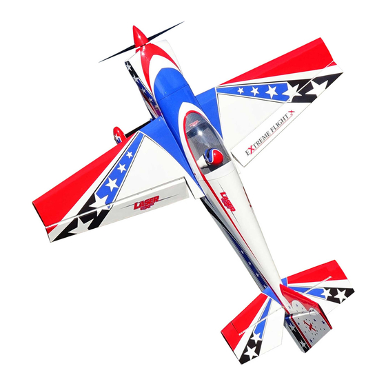
- Page 3 Introducing the brand new Extreme Flight 104" Laser EXP! The word is out that the Extreme Flight Laser EXP is THE machine for all things aerobatic. Whether you fly precision aerobatics, low and slow 3D, XA or a combination of them all our Laser series aircraft set the bar for modern aerobatic flight.
- Page 4 Your flying experience will be greatly enhanced once your plane is properly dialed in. 7. Extreme Flight now has their own Vimeo channel. There are many assembly videos providing extreme detail on certain aspects of the...
- Page 5 11. EF anodized servo arms 12. EF black socket head servo screws 30 or 100pk 13. EF anodized washer set, color match 14. EF color match velcro, 2m X 20mm 15. EF servo safety clips All items above are available from Extreme Flight RC.
- Page 6 Horizontal and wing assembly 1. Locate your horizontal stabilizer, elevator and associated hardware, see figures 1& 2. Let's begin by removing the elevator and extract all pin hinges. You will notice the 3 hinges closest to the root of the horizontal stabilizer are clipped along their length, see figure 2.
- Page 7 Figure 2 2. Be sure the 3 clipped hinges go into the first 3 holes from the root and that the hinge is at its midpoint into the hole and allow to dry. Clean any excess epoxy with a paper towel soaked with rubbing alcohol.
- Page 8 Figure 3 Figure 4 6. Next we will install the servo and linkage setup. Locate your servo, servo arm and all the hardware, see figure 1, for the horizontal stabilizer/elevator. We begin by installing the servo into the horizontal stabilizer, you will note the slot within the servo bay is oriented to the trailing edge, this is for your servo wire as your servo output shaft will be oriented to the trailing edge of the horizontal stabilizer.
- Page 9 Figure 5 Figure 6 Now take your3mm bolt, then insert a washer, then thru the ball link, next install the conical then thread the bolt onto the servo arm and use BTL. If using an EF servo arm, they have double thickness and a locknut is not necessary but can be installed if desired, however on other brand arms a locknut is usually necessary as they are not as thick.
- Page 10 Figure 7 Repeat the entire processfor the other horizontal stabilizer and elevator.\ Figure 8...
-
Page 11: Wing Assembly
Wing Assembly 7. The wing assembly is nearly identical to the horizontal stabs. Start with hinging, I recommend putting the hinges into the wing first then mate the aileron. Now move to installing your control horns, both of these items use the same techniques as the horizontal stabilizer and elevator. -
Page 12: Tailwheel Assembly
Note: in the upper right hand of Figure 10 that is a MPX multi wire servo plug, it makes aileron wire connections very easy. Available at Extreme Flight RC. Figure 10 Tailwheel assembly 8. The tailwheel assembly begins with identifying your parts, see Figure 11. Apply some BTL on your 3mm mounting bolts, with washer, and secure the tailwheel assembly to the mounting plate. - Page 13 Figure 11 . Figure 12...
-
Page 14: Landing Gear
Landing Gear 9. Locate your landing gear, wheel cuffs, wheel pants and main landing gear hardware package. See figures 13 and 14 for parts identification. Figure 13 Figure 14... - Page 15 Take a very close look at the landing gear, you will notice one side is perfectly straight and the other side has a very slight angle. The straight side goes forward, if you are having trouble seeing this, try laying the gear on a flat surface. Flip the gear to each side and it will become easy to notice which side is straight and angled.
-
Page 16: Engine And Fuel Tank Installation
Figure 16 Engine and Fuel Tank Installation 10. If you are using the DA120 this step will be quite simple, figure 18 will help identify the various parts. The firewall has marks that show the location of the holes to mount the standoff. - Page 17 Figure 17 Figure 18...
- Page 18 Figure 19 Figure 20...
- Page 19 Figure 21 11. A 120cc motor will yield a 10-15 minute flight using a 34oz tank, this makes the Extreme Flight RC 34oz Flowmaster tank the perfect choice. There is a tray just over the wing tube that is custom made for the fuel tank of your choice. We also used Flowmaster fuel line to complete the plumbing for the tank.
- Page 20 12. Plumb your tank as desired and it will usually result in the need for a fuel dot, I chose to use an Extreme Flight RC fuel dot, blue or black are likely choices see figure 23. I mounted mine on the right side of the fuselage near the cowling. Figure 24 will show the overall installation of the fuel tank.
- Page 21 10. The cowling can now be trial fit to the fuselage. If using standard mufflers, you will need to cut holes for the exhaust stacks. Since it is a two piece cowling I simply held the bottom portion as close to its intended position and then slid it up against the bottom of the muffler stacks and made marks to cut exit holes.
- Page 22 Figure 26 If you prefer a tuned pipe or canister installation then laser cut piece of plywood is cut and provided to make this easier. It also includes silicon tubing to secure your desired exhaust system. Also 70mm drop headers are needed to reach your pipes. We strongly suggest trial fitting your exhaust before beginning the final installation.
- Page 23 Figure 28 Figure 29...
- Page 24 Rudder and Center of Gravity location 11. Locate the rudder and associated parts bag. This Laser has a removable rudder, as such the assembly is simplified from what you may be used to. The hinges are already glued in so we may proceed to installing the rudder.
- Page 25 elevators/ailerons. We used the outer hole on the 2” servo arm. Note: if you did not insert the tailwheel tiller arm into the ball link earlier in this step make sure to do that now before connecting the remaining ball link into the control horn. Also be sure to recheck the Rudder hinge pin located on the top of the rudder, add some BTL and be sure not to over tighten.
- Page 26 Figure 32 Figure 33...
- Page 27 27X11/28X9.5/28X10/29X9 to all be very good prop choices. The spinner we used is a 5” red carbon fiber, the spinner and props are available thru Extreme Flight RC. The rudder/elevators/wings/canopy are all removable items, be sure to check them and make sure all connections are made.
-
Page 28: Setup And Flying
Setup and Flying Throws: Low rates Middle rates High rates Ailerons 25° 32° 38° Elevators 15° 45° 55° Rudder As desired All you can get A digital throw meter is highly recommended for accurate setup of control surface throws. The above throws are what we used in the videos, exponential is as follows: Low 25-30% Middle 35-40% High 45-50%... -
Page 29: General Information
Thanks again for your purchase of the Extreme Flight RC 104 inch Laser EXP ARF. I hope you enjoy assembling and flying yours as much as I have mine.
Need help?
Do you have a question about the 104 Laser EXP ARF and is the answer not in the manual?
Questions and answers