
Related Manuals for golmar 2PLUS


Summary of Contents for golmar 2PLUS
- Page 1 Cód. 50124627 Audio door entry system 2 wires without polarity 2PLUS installation manual T2PLUSML rev.0112...
-
Page 2: Table Of Contents
INTRODUCTION First of all we would like to thank and congratulate you for the purchase of this product manufactured by Golmar. The commitment to reach the satisfaction of our customers is stated through the ISO-9001 Certification and for the manufacturing of products like this one. -
Page 3: Starting Recommendations
Up to 3 access door pannels being not necessary the use of switching units. (Up to 2 access door pannels if there is a digital converter CD-2PLUS in the building or backbone). Up to 120 telephones per instalation without using converters. -
Page 4: Door Panel
DOOR PANEL DESCRIPTION oor panel description. Closing heads CE-6xx embedding boxes 2xxx grille module 3xxx push buttons module EL520 Sound module Push buttons encoder , in systems with more than eight push buttons. EL516SE Relay unit EL512 , in systems with more than three push buttons modules. -
Page 5: Embedding Box Positioning
DOOR PANEL INSTALLATION mbedding box positioning. 1850 1650 1450 Make a hole on the wall in order to place the upper part of the door panel at 1,65m height. The hole dimensions will depend on the number of door panel modules. Modules Compact CE630... -
Page 6: Modules Assembly
DOOR PANEL INSTALLATION lace the embedding box. Pass the wiring through the hole made in the embedding box. Fit, flush and level it. Then, once it is placed, remove the protective labels from the fixation holes of the door panel. oor panel modules assembly. -
Page 7: Electronic Circuits Assembly
DOOR PANEL INSTALLATION ound module assembly. Insert the sound module in the grille module. For a proper assembly, align the light push button and the microphone of the sound module with its own holes in the grille module. ixing the door panel into the embedding box. Choose a direction to open the door panel;... -
Page 8: Placing The Nameplate Labels
DOOR PANEL INSTALLATION lace the nameplate label of the push buttons. Open the label holder. Place the label and close. ush button wiring. For a quality finish, pass the wires through the hole arranged on the nearest module holder. It is advisable to use wires with sections between 0,1 and 0,25mm . - Page 9 DOOR PANEL INSTALLATION ush buttons wiring. Plug the push buttons connecting wires in the CN4 connector of the sound module EL520, this wire consists of 10 conductors (P1 to P8, B and CP) for the push buttons connection or encoder circuits EL516SE. The CP terminal must be connected to the push buttons common terminal and to the CP terminal of the push buttons encoder circuit.
-
Page 10: Push Button Coding
0 + 15 + 15 + 15 +15 + 15 + 15 + 15 +15 = 120 ush buttons code. In case of combined equipment with coded panels or port’s exchange (requires CD-2PLUS converter), it will be necessary to know the code of each push button as it is shown on the attached chart. -
Page 11: El520 Configuration
Set the switch to ON in case of call forwarding from the door panel to the porter’s exchange (when it is activated). Set the switch to OFF if this function is not required (it needs a CD-2PLUS converter and that door panel capture is activated in the porter’s exchange). -
Page 12: Lamps Wiring
DOOR PANEL INSTALLATION amps wiring. Once the nameplate labels are placed, wire the lamps from all the modules with the terminals L1 and L2 of the sound module. IMPORTANT: If there are more than three push buttons modules, use the EL512 relay to supply the lamps (see diagram in page 69). -
Page 13: Power Supply Installation
POWER SUPPLY INSTALLATION nstalling the FA-PLUS/C ver. 938072 power supply. Install or modify the equipment without the power connected. The installation and handling of these equipments must be performed by authorised personnel. Install the power supply in a dry and protected place without risk of drip or water projections. Avoid to place it near to heating sources, in dusty locations or smoky enviroments. -
Page 14: Description
JP1 jumper inserted, it operates as an additional free-voltage push button (PA and PB contact, see page 69), or activates the SAR- 2PLUS digital relay unit if the jumper inserted is JP2 (see page 69). erminal connection description. -
Page 15: Jp3 Jumper Config. (Only T-7822Vd)
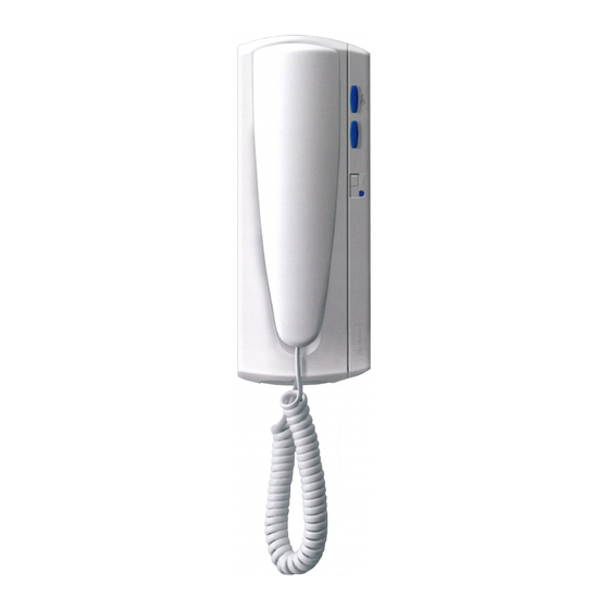
V2Plus system (video) BUS: Digital communication bus. End of Line: No function. 2Plus system (Audio) *Factory default TELEPHONE INSTALLATION ix the telephone to the wall. For wiring and fixing purposes, it is necessary to open the telephone. Lever slightly with a plain screwdriver into the slots as it is shown in the picture. -
Page 16: Programming
If you don’t, the door panel will emit a sound to advise that the system is still into the programming mode. IMPORTANT: Installation with CD-2PLUS converter and coded panel or porter´s exchange, the call code linked to telephones will be from 1 up to 250. -
Page 17: Door Bell Push Button
OPTIONAL CONNECTIONS T-7720, T7722VD oor bell push button connection. or T-7822VD The T-7720, T-7722VD and T-7822VD telephones, incorporate as standards the call reception from the door bell push button. This feature spares the use of a bell, by placing a push button between the 'HZ' telephone terminals. -
Page 18: Optional Connections
The auxiliary push button of the T-7722VD and T-7822VD telephones has two possible functions which are configurable by JP1 and JP2 jumpers: Activate the SAR-2PLUS unit to switch on the ligths, etc. See document TSAR-2Plus for its connection and configuration. -
Page 19: Garage Door Release
BUS HZ PA PB BUS HZ PA PB BUS F .Ligne Activating the garage door to 12Vac Main door panel FA-PLUS/C ver. 938072 TF-104 SAR-12/24 CV1 +12 230110 0 Main Main IMPORTANT: Do not insert the resistor with a 2Plus system. -
Page 20: With D.c Lock Release
T-7822VD T-7822VD BUS HZ HZ BUS HZ PA PB BUS F .Linea BUS HZ PA PB BUS F .Linea Slave door panel FA-PLUS/C ver. 938072 CV1 +12 230110 0 Main IMPORTANT: Do not insert the resistor with a 2Plus system. - Page 21 udio door entry system with d.c. lock release. The installation diagram shows the wiring of an audio door entry system with one or several door panels to enter into the building. If the system has one door panel only, do not take into account the connection towards others. If the system has more than one door panel, wire the second panel as shown on the diagram.
-
Page 22: With A.c Lock Release / Tf104
INSTALLATION DIAGRAMS Next floor T-7720 T-7722VD BUS HZ HZ BUS HZ PA PB T-7720 T-7722VD BUS HZ PA PB T-7720 T-7822VD BUS HZ PA PB BUS F .Ligne Slave door panel FA-PLUS/C TF-104 ver. 938072 230110 0 CV1 +12 Main Main... - Page 23 udio door entry system with a.c. lock release and additional TF-104 transformer. The installation diagram shows the wiring of an audio door entry system with one or several door panels to enter into the building. If the system has one door panel only, do not take into account the connection towards others. If the system has more than one door panel, wire the second panel as shown on the diagram.
-
Page 24: With A.c Lock Release / El502
BUS HZ PA PB T-7720 T-7822VD BUS HZ PA PB BUS F .Ligne Slave door panel FA-PLUS/C ver. 938072 EL502 CN2 CN3 230110 0 - - + CV1 +12 Main IMPORTANT: Do not insert the resistor with a 2Plus system. - Page 25 udio door entry system with a.c. lock release and EL502 dc/ac converter. The installation diagram shows the wiring of an audio door entry system with one or several door panels to enter into the building. If the system has one door panel only, do not take into account the connection towards others. If the system has more than one door panel, wire the second panel as shown on the diagram.
-
Page 26: Troubleshooting Hints
TROUBLESHOOTING HINTS An easy way to check that the system is working properly, is to disconnect the wiring and test a terminal (telephone) directly connected to the door panel installation. Any short-circuit between different terminals of the system will not damage the connected units. Nothing operates. -
Page 27: Notes
NOTAS / NOTES... -
Page 28: Compliance
Golmar se reserva el derecho a cualquier modificación sin previo aviso. Golmar se réserve le droit de toute modification sans préavis. Golmar reserves the right to make any modifications without prior notice.
Need help?
Do you have a question about the 2PLUS and is the answer not in the manual?
Questions and answers