
Related Manuals for golmar Stadio Plus 4113/AL


Summary of Contents for golmar Stadio Plus 4113/AL
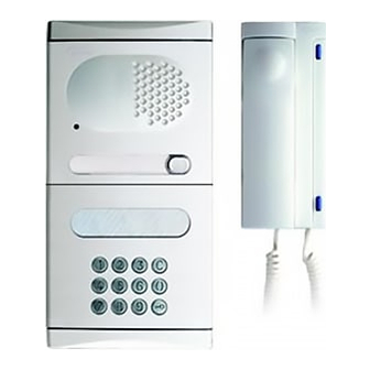
- Page 1 T4003EN rev.0105 Audio door entry system Kits with access control Stadio Plus Instructions manual...
-
Page 2: Table Of Contents
INTRODUCTION First of all we would like to thank and congratulate you for the purchase of this product manufactured by Golmar. The commitment to reach the satisfaction of our customers is stated through the ISO-9001 certification and for the manufacturing of products like this one. -
Page 3: Power Supply Installation
POWER SUPPLY INSTALLATION DOOR PANEL INSTALLATION nstalling the TF-104 transformer. reparing the embedding box. The transformer must be installed in a dry and Break the bottom flange protected place. It's recommended to protect to pass the cables through. 3,5 x 25 the transformer by using a thermo-magnetic DIN-7971 circuit breaker. -
Page 4: Access Control Description
DOOR PANEL INSTALLATION ACCESS CONTROL DESCRIPTION lace the nameplate labels. odule description Installation terminal connector is located on the rear part of the module. The correspondance of each terminal is as follows: Open the label holder. ~, ~ : power supply input. B+ : positif for battery. -
Page 5: Programming Structure And Sequence
ACCESS CONTROL PROGRAMMING ACCES CONTROL PROGRAMMING nter and exit from unction fields and values. programming. The module is delivered with factory default values: for security reasons, the relay activation To enter into the programming menu, press key symbol and enter codes are delivered with a non valid value. - Page 6 ACCESS CONTROL PROGRAMMING ACCES CONTROL PROGRAMMING Coming from previous page Coming from previous page unction fields and values. unction fields and values. It defines the 7th activation code of the relay n.1. It defines the activation code of the panic function. Proceed as detailed on 11 field.
-
Page 7: Duplicated Codes
ACCESS CONTROL PROGRAMMING TELEPHONE INSTALLATION Coming from previous page unction fields and values. escription of the T-902 telephone. Telephone handset. It defines the installer PIN code to enter into programming Speaker grille. mode. Microphone hole. A 6 digits code must be always used. Once this code Subjection hole. -
Page 8: Lock Release Installation
LOCK RELEASE INSTALLATION INSTALLATION DIAGRAM ock release installation. udio door entry system. T-902 3,5 x 25 DIN-7972 If the lock release will be installed in a metal door, use a Additional push button Ø3,5mm. drill and tap the hole . In case of wood door, use a Ø3mm. -
Page 9: Quick Programming Guide
INSTALLATION DIAGRAM QUICK PROGRAMMING GUIDE nd relay connection. uick programming guide. Relay nr. 1 is reserved for the connection of the door panel lock release, as it's shown on Codes lenght (4, 5 or 6 digits) previous page. Relay nr. 2 operates on single shoot mode only. Use a TF-104 transformer to connect a 2nd lock release;... -
Page 10: Troubleshooting Hints
TROUBLESHOOTING HINTS Nothing operates. Check the output transformer voltage between SEC terminals: it should have 12 to 17Va.c. If not, disconnect the transformer from the installation and measure again. If it's correct now, it means there is a short circuit in the installation: disconnect the transformer from mains and check the installation. - Page 11 Golmar se reserva el derecho a cualquier modificación sin previo aviso. Golmar se réserve le droit de toute modification sans préavis. Golmar reserves the right to make any modifications without prior notice.
Need help?
Do you have a question about the Stadio Plus 4113/AL and is the answer not in the manual?
Questions and answers