Table of Contents
Advertisement
Quick Links
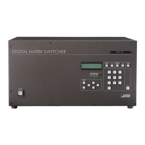
DIGITAL MATRIX SWITCHER
POWER
Thank you for choosing our product.
To ensure the best performance of this product, please read this User's Guide fully and carefully before
using it and keep this manual beside this product.
FDX-32
PRESET
OFF
ALL
INPUT
OUTPUT
LOAD
7
8
9
SWITCHING MODE
V&A
VIDEO
AUDIO
4
5
6
MENU
1
2
3
/SET
SET
0
ESC
RS-232C
LAN
INPUT
A
B
1
~
4
A
D
DVI-D(HDMI)
DVI-D(HDMI)
INPUT
A
B
5
~
8
A
D
DVI-D(HDMI)
DVI-D(HDMI)
INPUT
A
B
9
~
12
A
D
DVI-D(HDMI)
DVI-D(HDMI)
INPUT
13 16
~
A
D
LINK
LINK
A
HDBaseT
B
HDBaseT
INPUT
17 20
~
A
D
LINK
LINK
A
HDBaseT
B
HDBaseT
INPUT
21 24
~
A
D
LINK
LINK
A
HDBaseT
B
HDBaseT
INPUT
25 28
~
A
D
RX
TX
RX
TX
A
OPTICAL
B
OPTICAL
INPUT
~
29 32
A
D
RX
TX
RX
TX
A
OPTICAL
B
OPTICAL
IDK Corporation
Digital Matrix Switcher
OPTION
ALARM
S/N
UPDATE
C
D
A
DVI-D(HDMI)
DVI-D(HDMI)
DVI-D(HDMI)
C
D
A
DVI-D(HDMI)
DVI-D(HDMI)
DVI-D(HDMI)
C
D
A
DVI-D(HDMI)
DVI-D(HDMI)
DVI-D(HDMI)
LINK
LINK
LINK
C
HDBaseT
D
HDBaseT
A
HDBaseT
LINK
LINK
LINK
C
HDBaseT
D
HDBaseT
A
HDBaseT
LINK
LINK
LINK
C
HDBaseT
D
HDBaseT
A
HDBaseT
RX
TX
RX
TX
RX
TX
C
OPTICAL
D
OPTICAL
A
OPTICAL
RX
TX
RX
TX
RX
TX
C
OPTICAL
D
OPTICAL
A
OPTICAL
FDX-32
<User's Guide>
Ver.2.2.0
POWER
BREAKER
AC 100-240V
50/60Hz
FG
B
C
D
OUTPUT
DVI-D(HDMI)
DVI-D(HDMI)
DVI-D(HDMI)
1
~
4
A
D
B
C
D
OUTPUT
~
DVI-D(HDMI)
DVI-D(HDMI)
DVI-D(HDMI)
5
8
A
D
B
OUTPUT
DVI-D(HDMI)
9
~
12
A
D
OUTPUT
LINK
LINK
LINK
13 16
~
B
HDBaseT
C
HDBaseT
D
HDBaseT
A
D
OUTPUT
LINK
LINK
LINK
17 20
~
B
HDBaseT
C
HDBaseT
D
HDBaseT
A
D
OUTPUT
LINK
~
21 24
B
HDBaseT
A
D
RX
TX
RX
TX
RX
TX
OUTPUT
25 28
~
B
OPTICAL
C
OPTICAL
D
OPTICAL
A
D
RX
TX
OUTPUT
~
29 32
B
OPTICAL
A
D
Advertisement
Table of Contents

Related Manuals for IDK FDX-32


Summary of Contents for IDK FDX-32
- Page 1 Digital Matrix Switcher FDX-32 <User’s Guide> Ver.2.2.0 DIGITAL MATRIX SWITCHER FDX-32 PRESET INPUT OUTPUT LOAD SWITCHING MODE V&A VIDEO AUDIO MENU /SET POWER POWER BREAKER AC 100-240V RS-232C OPTION 50/60Hz ALARM UPDATE INPUT ~ OUTPUT DVI-D(HDMI) DVI-D(HDMI) DVI-D(HDMI) DVI-D(HDMI) DVI-D(HDMI)
- Page 2 FDX-32 User’s Guide Trademarks ● Blu-ray Disc and Blu-ray are trademarks of Blu-ray Disc Association. ● The terms HDMI and HDMI High-Definition Multimedia Interface, and the HDMI Logo are trademarks or registered trademarks of HDMI Licensing, LLC in the United States and other countries.
- Page 3 Some of the contents in this User’s Guide such as appearance diagrams, menu operations, communication commands, and so on may differ depending on the version. This User’s Guide is subject to change without notice. You can download the latest version from IDK’s website at: http://www.idk.co.jp/en/index.html The reference manual for FDX-32 consists of the following two volumes: ■...
-
Page 4: Safety Instructions
FDX-32 User’s Guide Safety instructions Read and understand all safety and operating instructions before using this device. Follow all instructions and cautions as detailed in this document. Enforcement Symbol Description Indicates the presence of a hazard that may result in death or serious... - Page 5 The product is intended to be installed by skilled technicians. For installation, please contact a system integrator or IDK. Otherwise, it may cause fire, electric shock, injury, or property damage. Set the power plug in a convenient place to unplug easily.
- Page 6 FDX-32 User’s Guide Caution Double Pole/Neutral Fusing. Electrical Hazard Do not place the product in any place where it will be subjected to high temperatures. If the product is subjected to direct sunlight or high temperatures, it may cause fire.
- Page 7 FDX-32 Users Guide Altitude: Do not place the product at elevations of 2,000 meters (6562 feet) or higher above sea level. Failure to do so may shorten the life of the internal parts and result in malfunctions. Instruction Caution: If you lift the FDX with your knees straight fully, your back may be damaged.
-
Page 8: Table Of Contents
FDX-32 User’s Guide Table of Contents Included items .............................11 Product outline ............................12 Features ..............................15 Panels ..............................17 Front panel ...........................17 Rear panel ...........................18 Output slot board’s channel configuration ..................20 Sample system diagram ........................21 Precautions ............................22 Installation ............................22 Cabling............................23 6.2.1 Twisted pair cable ........................23 6.2.2 SFP module ..........................24... - Page 9 FDX-32 Users Guide 8.5.4 Time for ignoring video output request signals [OUTPUT HPD MASK] ........49 8.5.5 Deep color [OUTPUT DEEP COLOR] ...................50 [OUTPUT TIMING] ........................51 8.6.1 Output resolution [OUTPUT RESOLUTION] ................51 8.6.2 Aspect ratio [OUTPUT ASPECT] ...................52 8.6.3 Test pattern output [OUTPUT PATTERN] ................53 8.6.4...
- Page 10 FDX-32 User’s Guide 8.12.8 Displaying sink device status [MONITOR STATUS] ...............81 8.12.9 Displaying slot board status [BOARD STATUS] ..............81 8.12.10 Displaying cooling fan status [FAN STATUS] ..............82 8.12.11 Displaying supply voltage status [POWER STATUS] ............83 8.12.12 Displaying firmware and hardware versions [VERSION] ............84 WEB browser ............................85...
-
Page 11: Included Items
FDX-32 Users Guide 1 Included items Make sure all items below are included in the package. If any items are missing or damaged, please contact IDK. DIGITAL MATRIX SWITCHER FDX-32 INPUT OUTPUT PRESET LOAD SWITCHING MODE V&A VIDEO AUDIO MENU... -
Page 12: Product Outline
FDX-32 User’s Guide 2 Product outline FDX-32 has 32 inputs and 32 outputs. Since this HDMI/DVI Digital Matrix Switcher supports HDCP, video whose copyright is protected, such as Blu-ray, can be input. HDMI signals can also be input via a conversion cable. - Page 13 FDX-32 Users Guide FDX-32 Up to outputs / 4 slot boards Up to inputs / 4 slot boards Digital output slot board 4 Outputs / 1 slot board Digital Video / Audio Output EQ Transmitter HDMI DVI Up to 131 ft. (approx.) / 40 m HDBaseT output slot board 4...
- Page 14 FDX-32 User’s Guide ● Twisted pair output slot board (4 outputs) Four RJ-45 connectors are mounted that can output video and audio signals of the selected input channel. Those digital (video/audio) signals can be extended up to 100 m/328.08 ft. when the HDC-R series and FDX series are used together.
-
Page 15: Features
FDX-32 Users Guide 3 Features ■ Video ・The maximum resolution: QWXGA (RB) , 1080p ・Digital cable equalizer function (digital I/O slot board) Input: Up to 10 m to 30 m/32.8 to 98.43 ft. Output: Up to 10 m to 40 m/32.8 to 131.23 ft. - Page 16 FDX-32 User’s Guide ■ Others ● EDID emulation (with copy function) ● Switching video and audio separately (when optional MAU-3232 is connected) ● I/O slot board, CPU slot board, and fan unit can be replaced without removing from the rack.
-
Page 17: Panels
FDX-32 Users Guide 4 Panels 4.1 Front panel ⑥ ⑧ ⑤ DIGITAL MATRIX SWITCHER FDX-32 PRESET INPUT OUTPUT LOAD SWITCHING MODE V&A VIDEO AUDIO MENU /SET POWER ⑦ ① ② ③ ④ [Fig. 4.1] Front panel drawing Part name Description ①... -
Page 18: Rear Panel
FDX-32 User’s Guide 4.2 Rear panel ⑦ ⑧ ⑨⑩ ⑪ ⑫ ⑬ ⑭ ⑮ POWER BREAKER AC 100-240V OPTION 50/60Hz RS-232C ALARM UPDATE INPUT ~ OUTPUT ~ DVI-D(HDMI) DVI-D(HDMI) DVI-D(HDMI) DVI-D(HDMI) DVI-D(HDMI) DVI-D(HDMI) DVI-D(HDMI) DVI-D(HDMI) INPUT ① ④ ~ OUTPUT... - Page 19 FDX-32 Users Guide Part name Description ① DVI input connectors For DVI-I cables and DVI-D cables (analog signals cannot be used). (DVI-D HDMI) HDMI signals can be input using an HDMI-DVI conversion cable. ② HDBaseT input ports Digital (video/audio) signals can be extended up to 100 m/328.08 ft.
-
Page 20: Output Slot Board's Channel Configuration
FDX-32 User’s Guide 4.3 Output slot board’s channel configuration ・ The number of outputs can be customized using 2 (scan converter output slot board) or 4 channels. ・ The first two channel numbers of scan converter output slot board are valid. Other two channels are invalid. -
Page 21: Sample System Diagram
For DVI cable, please use DVI-I or DVI-D single link cable (male connector) which supports DVI Rev1.0. For twisted pair cable, please use UTP / STP cable which support Cat5e / Cat6 standard. IDK recommends our CAT.5E HDC cable. For fiber optic cable, please use one duplex fiber or two simplex fibers which have LC connectors and meet standards depending on extension distance. -
Page 22: Precautions
FDX-32 User’s Guide 6 Precautions Before connecting to external devices, follow the precautions below. 6.1 Installation When installing the FDX, please observe the following precautions. ● Do not place the FDX on top of another FDX. ● Do not block vent holes. Please secure the space above ambient 30 mm/1.18 inches. -
Page 23: Cabling
50 m/164.04 ft. Cat6 * CAT.5E HDC cable developed by IDK Corporation is double shielded twisted pair cable for high quality video transmission. It protects video signal from external noise or other interferences by having double shielded structure. Its transmission characteristic meets 500 MHz up to 100 m/328.08 ft., and it is certified and recommended by HDBaseT alliance. -
Page 24: Sfp Module
FDX-32 User’s Guide 6.2.2 SFP module The fiber type and extension distance to be used vary depending on the SFP module. [Table 6.2] Specifications of standard SFP modules Multimode fiber Singlemode fiber Wave length 850 nm (Oxide VCSEL laser*) 1310 nm (Fabry-Perot laser*) OM3: 300 m/984.25 feet... -
Page 25: Fiber Optic Cable
To output alarm for cooling fan, power, and input/output from the FDX, pleas connect attached terminal block (2-pin) to ALARM connector. IDK recommends using AWG 28 to AWG 16 cables. The maximum pealing length is 7 mm / 0.28” approx. -
Page 26: Basic Operation
FDX-32 User’s Guide 7 Basic operation 7.1 Selecting Input/output channel Procedure Select the desired switching mode Selecting using the “SWITCHING MODE” input/output key.* channel Press the “INPUT” key to move to the input channel selection LCD PRESET INPUT OUTPUT LOAD screen.*... - Page 27 FDX-32 Users Guide You can select whether channels of the FDX and optional MAU-3232 are switched in tandem with each other from the following three modes using the SWITCHING MODE key. ● V&A mode: Turns orange; switching I/O channels of both the FDX and MAU-3232 together.
-
Page 28: Menu Operation Key
FDX-32 User’s Guide 7.2 Menu operation key The menu consists of the top page, main menu, sub menu, and setting page. The screen backlight is turned off if no operation is performed for 10 seconds (power saving function). 【See 8.12.3 Power saving [POWER SAVE]】... - Page 29 FDX-32 Users Guide Available “▲”, “▼”, “”, and “” keys are displayed at the lower right of the LCD screen and the key LED lights. A channel that does not have its slot board cannot be set. The set value will be saved after the operation.
-
Page 30: Loading Preset Memory
FDX-32 User’s Guide 7.3 Loading preset memory FDX can read registered preset memory and set input/output channels. If you operate “Selecting input/output channel” or “Menu operation” during loading preset memory, the operation will move to the operated operations. 【See:7.1 Selecting Input/output channel】... -
Page 31: Initialization
FDX-32 Users Guide 7.4 Initialization All settings can be reset to factory default values by turning on the FDX while pressing the “ESC” key. Press and hold the “ESC” key until you hear short beep sounds. Once you have initialized the settings, they cannot be reversed. -
Page 32: Setting/Releasing Key Lock
FDX-32 User’s Guide 7.5 Setting/Releasing key lock The key lock of front keys can be set/released by pressing the “ESC” key for five seconds (approx.). Press and hold the “ESC” key until you hear a long beep sound. Front keys are divided into some groups, and you can select the target group. -
Page 33: Menus
FDX-32 Users Guide 8 Menus Menus that can be set in the FDX are divided into the following groups: Displaying I/O channel status: CHANNEL DISPLAY Setting input: INPUT SETTING Setting input timing: INPUT TIMING * Setting output: OUTPUT SETTING ... - Page 34 FDX-32 User’s Guide ■ Setting output ( OUTPUT SETTING ) Setting Menu name Function Page Set value Default value OUTPUT EQUALIZER Output equalizer OFF (Without automatic correction)/LOW/ Each OFF (Without correction) MEDIUM/HIGH output OUTPUT MODE Output mode AUTO/HDMI RGB/HDMI 422/HDMI 444/DVI...
- Page 35 FDX-32 Users Guide ■ Setting audio (AUDIO) Setting Menu name Function Page Set value Default value AUDIO DIGITAL OUT Digital audio output ON/OFF Each output ■ Setting EDID (EDID) Setting Menu name Function Page Set value Default value EDID DATA...
- Page 36 FDX-32 User’s Guide ■ Setting RS-232C communication (COM PORT) Setting Menu name Function Page Set value Default value - COM PORT SETUP RS-232C communication Baud rate: 4800/9600/14400/19200/38400 [bps] Baud rate: 9600 [bps] Data bit length: 7/8 [bit] Data bit length : 8 [bit]...
-
Page 37: Displaying I/O Channel Status [Cross Point]
FDX-32 Users Guide 8.2 Displaying I/O channel status [CROSS POINT] 8.2.1 Displaying current I/O channel status [CHANNEL DISPLAY] Setting by menu CROSS POINT → CHANNEL DISPLAY [CHANNEL DISPLAY] OUT: 1 V: 1 A: 1 ① ② ③ [Fig. 8.1] LCD screen to display I/O channel status... -
Page 38: Setting Input [Input Setting]
FDX-32 User’s Guide 8.3 Setting input [INPUT SETTING] 8.3.1 [INPUT EQUALIZER] If you select “AUTO”, signals are corrected automatically depending on the amount of signal attenuation. Using menu INPUT SETTING → INPUT EQUALIZER Each input connector (IN1 to IN32) Set value... -
Page 39: No-Signal Input Monitoring Time [Input Signal Check]
FDX-32 Users Guide 8.3.2 No-signal input monitoring time [INPUT SIGNAL CHECK] Monitoring time for when the source device does not output video signals due to the changes of EDID or turning on/off the FDX. Use this menu to set the monitoring time which is from when a source device stops outputting signals to when the FDX requests the source device to output video signals. -
Page 40: Hdcp Input Enabled/Disabled [Input Hdcp]
FDX-32 User’s Guide 8.3.3 HDCP input enabled/disabled [INPUT HDCP] Some source devices check whether the connected device supports HDCP and then determine whether they encrypt HDCP signals or not. Since the FDX is HDCP compliant, if it is connected to a sink device that is not HDCP compliant, the sink device may not display video. -
Page 41: Input Timing]
FDX-32 Users Guide 8.4 [INPUT TIMING] 8.4.1 Horizontal starting position [INPUT H POSITION] Using menu INPUT TIMING → INPUT H POSITION Each input Set value :0 dot [default] :-100 dots to +100 dots -100 to +100 【NOTE】This menu can be selected if FDX has scan converter output slot boards. -
Page 42: Vertical Starting Position [Input V Position]
FDX-32 User’s Guide Using menu INPUT TIMING → INPUT H SIZE Each input Set value :0 dot [default] :-100 dots to +100 dots -100 to +100 【NOTE】This menu can be selected if FDX has scan converter output slot boards. 8.4.3 Vertical starting position [INPUT V POSITION] Using menu INPUT TIMING →... -
Page 43: Vertical Size [Input V Size]
FDX-32 Users Guide 8.4.4 Vertical size [INPUT V SIZE] Vertical size can be adjusted between -30 lines and +30 lines. If the set value is minus ( - ), the video image will be shown as reduced image to vertical direction. If set value is plus ( + ), the video image will be shown as enlarged image to vertical direction. -
Page 44: Input Aspect Ratio [Input Aspect]
FDX-32 User’s Guide 8.4.5 Input aspect ratio [INPUT ASPECT] Using menu INPUT TIMING → INPUT ASPECT Each input Set value AUTO :automatic adjustment [default] FULL :full screen :4:3 aspect ratio :5:3 aspect ratio :5:4 aspect ratio 16:9 :16:9 aspect ratio... -
Page 45: Brightness [Input Brightness]
FDX-32 Users Guide 8.4.7 Brightness [INPUT BRIGHTNESS] Using menu INPUT TIMING → INPUT BRIGHTNESS Each input Set value :100% [default] 100 % 80 % to 120 % :80 % to 120 % 【NOTE】This menu can be selected if FDX has scan converter output slot boards. -
Page 46: Sharpness [Input Filter]
FDX-32 User’s Guide 8.4.9 Sharpness [INPUT FILTER] Using menu INPUT TIMING → INPUT FILTER Each input Set value :softer filter (soft video image) -5 SOFT MIN to -1 SOFT :No filter [default] 0 NORMAL 1 SHARP to 15 SHARP MAX :sharper filter (sharp video image) 【NOTE】This menu can be selected if FDX has scan converter output slot boards. -
Page 47: Saturation [Input Saturation]
FDX-32 Users Guide 8.4.11 Saturation [INPUT SATURATION] Using menu INPUT TIMING → INPUT SATURATION Each input Set value :100 % 100 % [default] 0 % to 200 % :0 % to 200 % 【NOTE】This menu can be selected if FDX has scan converter output slot boards. -
Page 48: Output Setting]
FDX-32 User’s Guide 8.5 [OUTPUT SETTING] 8.5.1 Output equalizer [OUTPUT EQUALIZER] Using menu OUTPUT SETTING → OUTPUT EQUALIZER Each output connector (OUT1 to OUT32, ALL) Set value OFF: No correction [Default] MEDIUM HIGH 【NOTE】 If you use a 5 m/16.4 ft. or longer cable, we recommend that you test the configuration beforehand since it is greatly affected by the quality of the output signals and the like. -
Page 49: Forced Hdmi Signal Output [Output Hdmi Mode]
FDX-32 Users Guide 8.5.3 Forced HDMI signal output [OUTPUT HDMI MODE] The FDX acquires EDID from the sink device and determines if the sink device is an HDMI device or DVI device in order to output HDMI signals. However, if the FDX cannot acquire EDID for some reason, problems such as no audio input and the like may occur. -
Page 50: Deep Color [Output Deep Color]
FDX-32 User’s Guide 8.5.5 Deep color [OUTPUT DEEP COLOR] Using menu OUTPUT SETTING → OUTPUT DEEP COLOR Each output connector (OUT1 to OUT32) Set value 24Bit:24 bit / pixel ( 8 bit / component) [Default] 30Bit:30 bit / pixel ( 10 bit / component) 36Bit:36 bit / pixel (12 bit / component) -
Page 51: Output Timing]
FDX-32 Users Guide 8.6 [OUTPUT TIMING] 8.6.1 Output resolution [OUTPUT RESOLUTION] Using menu OUTPUT TIMING → OUTPUT RESOLUTION Each output connector (OUT1 to OUT32) Set value :Automatic output (current output resolution will be displayed) [Default] :VGA@60(640x480) 01: 640x 480 :SVGA@60(800x600) 02: 800x 600 :XGA@60(1024x768) -
Page 52: Aspect Ratio [Output Aspect]
FDX-32 User’s Guide 8.6.2 Aspect ratio [OUTPUT ASPECT] If you select “THROUGH”, the aspect ratio of the resolution selected in “8.6.1 Output resolution [OUTPUT RESOLUTION]” will be applied. If aspect ratio of the target sink device and the ratio set in “Output resolution”... -
Page 53: Test Pattern Output [Output Pattern]
FDX-32 Users Guide 8.6.3 Test pattern output [OUTPUT PATTERN] Using menu OUTPUT TIMING → OUTPUT PATTERN Each output connector (OUT1 to OUT32) Set value :no test pattern output [Default] :white and black stripes V-STRIPES :hatch CROSS HATCH WHITE RASTER :white :red... -
Page 54: Output Size [Output Size]
FDX-32 User’s Guide 8.6.4 Output size [OUTPUT SIZE] Using menu OUTPUT TIMING → OUTPUT SIZE Each output connector (OUT1 to OUT32) Set value :100 % [Default] 100 % 20.0 % to 400.0 % :20.0 % to 400 % 【NOTE】Channels that do not have a scan converter output slot board cannot be selected in this menu. -
Page 55: Blank Color [Output Blank Color]
FDX-32 Users Guide 8.6.6 Blank color [OUTPUT BLANK COLOR] The cursor set to displayed “A” position and change a setting, the blank color changes relatively from current red, green, and blue settings. By moving the cursor position to each red, green, and blue, the blank color can be changed individually. -
Page 56: Contrast [Output Contrast]
FDX-32 User’s Guide 8.6.8 Contrast [OUTPUT CONTRAST] Using menu OUTPUT TIMING → OUTPUT CONTRAST Each output connector (OUT1 to OUT32) Set value :100 % [Default] 100 % 0 % to 200 % :0 % to 200 % 【NOTE】Channels that do not have a scan converter output slot board cannot be selected in this menu. -
Page 57: Switching Effect [Output Fade Out-In]
FDX-32 Users Guide 8.6.10 Switching effect [OUTPUT FADE OUT-IN] Using menu OUTPUT TIMING → OUTPUT FADE OUT-IN Each output connector (OUT1 to OUT32) Set value :ON (switching effect) [Default] OFF :OFF (no switching effect) 【NOTE】Channels that do not have a scan converter output slot board cannot be selected in this menu. -
Page 58: Audio]
FDX-32 User’s Guide 8.7 [AUDIO] 8.7.1 Digital audio output [AUDIO DIGITAL OUT] Using menu AUDIO → AUDIO DIGITAL OUT Each output connector (OUT1 to OUT32) Set value ON [Default] 【NOTE】Channels that do not have an output slot board cannot be selected in this menu. -
Page 59: Edid]
FDX-32 Users Guide 8.8 [EDID] You can customize the EDID to be sent to the source device as needed. EXTERNAL (External EDID) Copied EDID 1 OUT 1 IN 1 Copied EDID 2 OUT 32 Copied EDID 3 Blu-ray player IN 32... -
Page 60: Edid Resolution [Edid Data]
FDX-32 User’s Guide 8.8.1 EDID resolution [EDID DATA] EDID to be sent to the source device In order to use values “05” to “24” which are built-in EDID, set the maximum resolution supported by the sink device. Using menu EDID → EDID DATA... - Page 61 FDX-32 Users Guide [Table 8.2] Max. resolution and number of EDID-supported pixels EDID supported 1360 1366 1024 1280 1280 1280 1280 1280 1400 1440 1600 1600 1680 1920 1920 2048 pixels 1024 1050 1200 1050 1080 1200 1152 Max. resolution -...
-
Page 62: Copying Edid [Edid Save]
FDX-32 User’s Guide 8.8.2 Copying EDID [EDID SAVE] EDID of the sink device can be read and saved, and the copied EDID can be registered in the FDX that is the same as built-in EDID. 【See: 8.8.1 EDID resolution [EDID DATA]】... -
Page 63: Deep Color [Edid Deep Color]
FDX-32 Users Guide 8.8.4 Deep Color [EDID DEEP COLOR] Deep Color (color depth) output from the source device 【See: 8.8.1 EDID resolution [EDID DATA]】 Using menu EDID → EDID DEEP COLOR Each input connector (IN1 to IN32) Set value 24Bit: 24 bit/pixel (8 bit/component) [Default]... -
Page 64: Audio Channel [Edid Speaker Ch]
FDX-32 User’s Guide 8.8.5 Audio channel [EDID SPEAKER CH] The number of channels to the audio of multi-channel output that is from the source device 【See: 8.8.1 EDID resolution [EDID DATA]】 Using menu EDID → EDID SPEAKER CH Each input connector (IN1 to IN32) -
Page 65: Linear Pcm Audio [Edid Linear Pcm]
FDX-32 Users Guide 8.8.6 Linear PCM Audio [EDID LINEAR PCM] The maximum sampling frequency of PCM audio that is output from the source device 【See: 8.8.1 EDID resolution [EDID DATA]】 Using menu EDID → EDID LINEAR PCM Each input connector (IN1 to IN32) -
Page 66: Aac Audio [Edid Aac]
FDX-32 User’s Guide 8.8.8 AAC Audio [EDID AAC] The maximum sampling frequency of AAC Audio that is output from the source device 【See: 8.8.1 EDID resolution [EDID DATA]】 Using menu EDID → EDID AAC Each input connector (IN1 to IN32) -
Page 67: Dts Audio [Edid Dts]
FDX-32 Users Guide 8.8.10 DTS Audio [EDID DTS] The maximum sampling frequency of DTS Audio that is output from the source device 【See: 8.8.1 EDID resolution [EDID DATA]】 Using menu EDID → EDID DTS Each input connector (IN1 to IN32) -
Page 68: Dolby Truehd Audio [Edid Dolby Truehd]
FDX-32 User’s Guide 8.8.12 Dolby TrueHD Audio [EDID Dolby TrueHD] The maximum sampling frequency of Dolby TrueHD Audio that is output from the source device 【See: 8.8.1 EDID resolution [EDID DATA]】 Using menu EDID → EDID Dolby TrueHD Each input connector (IN1 to IN32) -
Page 69: Setting Rs-232C Communication [Com Port]
FDX-32 Users Guide 8.9 Setting RS-232C communication [COM PORT] 8.9.1 RS-232C communication [COM PORT SETUP] Using menu COM PORT → COM PORT SETUP Set value (baud rate) 4800bps 9600bps [Default] 14400bps 19200bps 38400bps 7: data bit length is 7 bits... -
Page 70: Lan Communication [Lan]
FDX-32 User’s Guide 8.10 LAN communication [LAN] 8.10.1 IP address [IP ADDRESS] Using menu LAN → IP ADDRESS Set value 0.0.0.0 to 255.255.255.255 [Default] 192.168.1.199 【NOTE】If you do not press the “SET” key, the setting is not changed. 8.10.2 Subnet mask [SUBNET MASK] Using menu LAN →... -
Page 71: Tcp Port Number [Control Port]
FDX-32 Users Guide 8.10.3 TCP port number [CONTROL PORT] If you set the 8-connection configuration to OFF, 8 connections will be divided into 4 connections for web browser control and 4 connections for communication command control, and the HTTP port number will be “80”... -
Page 72: Setting Preset Memory [Preset Memory]
FDX-32 User’s Guide 8.11 Setting preset memory [PRESET MEMORY] 8.11.1 Loading preset memory [PRESET LOAD] Loading registered preset memory and apply the I/O channel setting Using menu PRESET MEMORY → PRESET LOAD Set value 01 to 32: Preset memory number 1 to 32 for loading [Default] All memory channels are not controlled.*... -
Page 73: Saving Preset Memory [Preset Save]
FDX-32 Users Guide 8.11.2 Saving preset memory [PRESET SAVE] You can save the current I/O channel status into the preset memory. Using menu PRESET MEMORY → PRESET SAVE Set value 01 to 32: Preset memory number 1 to 32 [Default] All memory channels are not controlled.*... -
Page 74: Editing Preset Memory [Preset Edit]
FDX-32 User’s Guide 8.11.3 Editing preset memory [PRESET EDIT] Using menu PRESET MEMORY → PRESET EDIT Set value The first page 01 to 32: Preset memory number 1 to 32 * [xxxxxxxxxx]: Preset memory name (up to 10 characters in ASCII code) -
Page 75: I/O Channel At Start-Up [Preset Start Up]
FDX-32 Users Guide 8.11.4 I/O channel at start-up [PRESET START UP] Settings other than the channels are automatically saved at the time of menu operation or setting change from the communication command, and the saved settings will be applied for the next start-up. You can select the setting for channels as follows. -
Page 76: Setting Other Functions [Others]
FDX-32 User’s Guide 8.12 Setting other functions [OTHERS] 8.12.1 Grouping keys for key lock [KEY LOCK] Using menu OTHERS → KEY LOCK Set value : Keys of ① are locked. [Default] MENU KEY LOCK : Keys of ① are not locked. -
Page 77: Power Saving [Power Save]
FDX-32 Users Guide 8.12.3 Power saving [POWER SAVE] Using menu OTHERS → POWER SAVE Set value : The backlight and key LEDs are turned off. [Default] If no key operation is performed for 10 seconds, the backlight will be turned off. -
Page 78: Alarm]
ON [Default] Rated voltage: 24 V Rated current: 300 mA In side of FDX-32 [Fig. 8.14] Circuit for alarm output In case a problem occurs in a cooling fan, power supply voltage, or I/O slot board, the relay will be closed and the contact between A and B will be set to ON. -
Page 79: Top Page [Top Display]
FDX-32 Users Guide 8.12.6 Top page [TOP DISPLAY] Using menu OTHERS → TOP DISPLAY Set value OFF: Normal [Default] ON: Statuses of input signals and sink device are displayed. If you select “ON” and press “▲” and “▼” keys while the top page is being displayed, pages displaying statuses of input signals (four pages) and sink device (two pages) can be displayed. - Page 80 FDX-32 User’s Guide ⑨Input slot board number ⑩For each slot board H: HDMI signals D: DVI signals Input signal status 4 : With HDCP SLOT01 :01 02 03 04 : With audio input H H D D ⑪Output channel number ⑫Audio status...
-
Page 81: Displaying Input Signal Status [Input Status]
FDX-32 Users Guide 8.12.7 Displaying input signal status [INPUT STATUS] Using menu OTHERS → INPUT STATUS 【See: 8.12.6 Top page [TOP DISPLAY]】 8.12.8 Displaying sink device status [MONITOR STATUS] Using menu OTHERS → MONITOR STATUS 【See: 8.12.6 Top page [TOP DISPLAY]】... -
Page 82: Displaying Cooling Fan Status [Fan Status]
FDX-32 User’s Guide 8.12.10 Displaying cooling fan status [FAN STATUS] Using menu OTHERS → FAN STATUS [FAN STATUS] 01:3720rpm OK ① ② ③ [Fig. 8.18] Page for displaying cooling fan status Description ① The cooling fan position 01 to 07 01 to 10 for redundant power supply (optional) Press “▲”... -
Page 83: Displaying Supply Voltage Status [Power Status]
FDX-32 Users Guide 8.12.11 Displaying supply voltage status [POWER STATUS] Using menu OTHERS → POWER STATUS OK: normal, NG: abnormal If the FDX has the second (optional) power supply unit, statuses of the first and second supply unit. [POWER STATUS]... -
Page 84: Displaying Firmware And Hardware Versions [Version]
FDX-32 User’s Guide 8.12.12 Displaying firmware and hardware versions [VERSION] Using menu OTHERS → VERSION Version information is displayed on four pages, and you can switch each page by pressing “▲” and “▼” keys. Hardware versions of input and output slot boards is available, and you can switch the page of each slot by pressing “◄”... -
Page 85: Web Browser
Open a web browser on the PC using the same LAN and type the IP address of the FDX in the address bar to open the operation window. 【NOTE】IDK has tested the operation on the Microsoft Internet Explorer 8.0 for Windows or greater. File Edit Settings Controls Window Help ①... - Page 86 FDX-32 User’s Guide Button name Description ① SWITCHING MODE Sets and displays a switching mode V&A: Switching I/O channels of both the FDX and (optional) MAU-3232 VIDEO: Switching I/O channels of only the FDX AUDIO: Switching I/O channels of only the MAU-3232 ②...
- Page 87 FDX-32 Users Guide ① ② ③ ④ ⑤ [Fig. 9.2] Screen for editing I/O channel name Button name Description Edits input channel name displayed in ”CROSS POINT”. ① CROSS POINT NAME “IN1” to “IN32” names are set as default. EDIT (for inputs)
-
Page 88: Specification
FDX-32 User’s Guide 10 Specification 10.1 Pin assignments 10.1.1 DVI-I connector Pin # Signal name Pin # Signal name TMDS data2- Hot plug detect TMDS data2+ TMDS data0- TMDS data2 shield TMDS data0+ N.C. TMDS data0 shield N.C. N.C. DVI-I 29 pin female DDC CLOCK- N.C. -
Page 89: Product Specification
FDX-32 Users Guide 10.2 Product specification Specifications and appearance are subject to change without notice. Item Description HDMI / DVI Up to 32 inputs Input Video HDBaseT - 4 inputs per board - Any combination of input boards can be install up to 8 boards and 32 inputs... - Page 90 FDX-32 User’s Guide Fiber optic extension input board (*7) 4 inputs / Optical signals for extension / HDMI (*8) / DVI 1.0 / HDCP 1.4 Number / Signal - TMDS single link - TMDS clock: 25 MHz to 225 MHz...
- Page 91 It does not support DVI signals with HDCP. If you need to extend DVI signals with HDCP, please use The IDK HDC-TD100 as a transmitter. RJ-45 connector is only for extending video, audio, power for a receiver, control signals using a Cat5e/Cat6 twisted pair cable. IDK receivers are required. Please do not connect LAN devices to this connector.
-
Page 92: Troubleshooting
FDX-32 User’s Guide 11 Troubleshooting In case this device does not work correctly, please check the following items first. Are this device and the connected devices turned on normally? Are cables connected correctly? Are there no loose connections? ... - Page 93 FDX-32 Users Guide Problem Cause/Check item/Solution Page Video output - Video is not output. [4] If a long cable is connected for input or output when digital I/O slot board is mounted, replace it with a 5 m/16.4 ft. or shorter Cable.
- Page 94 FDX-32 User’s Guide Problem Cause/Check item/Solution Page Interference or noise When an optical I/O slot board is mounted, are optical fiber cable type, appears on video. standard, polishing method, and laying method correct? Make sure that the both ends have LC connecter, the cable meets the SFP module standard, and the polishing method is correct.
- Page 95 FDX-32 Users Guide Problem Cause/Check item/Solution Page Video is displayed in Some sink devices do not find the color space of the input video purple or green. correctly, and the video may be displayed in purple or green. Set the correct color space in the output mode to solve this problem.
- Page 96 If additional assistance is required, please perform the following tests and then contact us. The problem occurs in all connectors? Connect the devices using genuine cables without connecting the FDX-32. The problem still cannot be solved? Please contact us for assistance.
- Page 97 FDX-32 Users Guide User’s guide of FDX-32 Ver.2.2.0 Issued on: 18 May 2017 Headquarters IDK Corporation 7-9-1 Chuo, Yamato-shi, Kanagawa-pref. 242-0021 JAPAN TEL: +81-46-200-0764 FAX: +81-46-200-0765 Email: idk_eng@idk.co.jp URL: http: //www.idk.co.jp/en/index.html IDK America Inc. 72 Grays Bridge Road Suite 1-C, Brookfield, CT 06804 TEL: +1-203-204-2445 Email: sales@idkav.com URL: http: //www.idkav.com...
Need help?
Do you have a question about the FDX-32 and is the answer not in the manual?
Questions and answers