Table of Contents
Advertisement
Quick Links
Advertisement
Table of Contents

Related Manuals for Timeguard PDRS1500N


Summary of Contents for Timeguard PDRS1500N
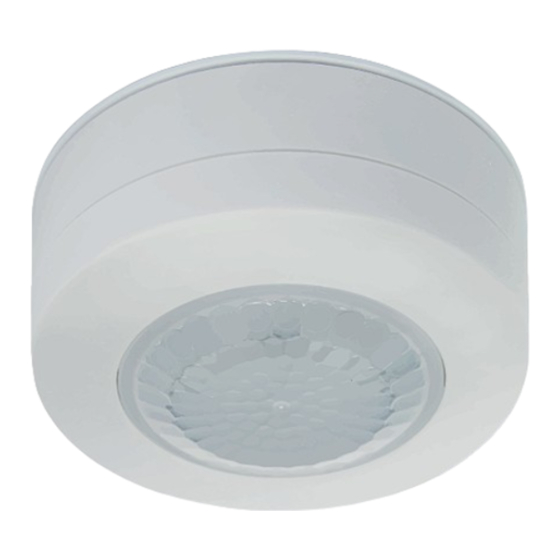
- Page 1 360° Surface Mount Ceiling PIR Light Controller Model: PDRS1500N...
-
Page 2: General Information
1. General Information These instructions should be read carefully and retained for further reference and maintenance. Timeguard reserve the right to alter these instructions Note: at any time. Up to date instructions will always be available for download at www.timeguard.com 2. - Page 3 Diameter 103, Depth 46mm • Multiple PIR Sensor Switching: A maximum of 8 PDRS1500N PIR sensors can be wired in parallel, to enable any detector to turn ON all the lights connected. (The total load must not exceed the lamp rating of a single PDRS1500N unit.
-
Page 4: Selecting A Location
4. Selecting a location • The PIR has a number of detection zones at various horizontal and vertical angles as shown below. The detection zones are a representation of the subjects walking path and not of the detection angle. Effective Approach Path Ineffective Approach Path (ACROSS) (TOWARDS) -
Page 5: Installation
• Reflective surfaces (i.e. pools of water, white painted walls, overhanging branches and other types of foliage) may cause false activation under heightened weather conditions. • During extreme weather conditions the PIR may exhibit unusual behaviour. Once normal weather resumes, the PIR will carry out normal operations. - Page 6 • Terminate the cable into the terminal block ensuring correct polarity is observed and that all bare conductors are sleeved (see section 6 Connection Diagram). • When wiring is complete, it is recommended that the ceiling mounting plate is fitted to the sensor body via the previously loosened x2 screws and fixed to the ceiling.
-
Page 7: Connection Diagram
6. Connection Diagram • Connect cables to the terminal block as follows; If the load connected to the PIR is of Class I construction, continue the earth continuity from the 230V 50hz mains circuit to the load. Parallel Wiring Connection Diagram... - Page 8 7. Setting Up Walk Test Procedure • Turn the power to the unit ON. The lamp will immediately illuminate as the unit goes through its “warm-up” period. After approximately 1 minute the lamp will extinguish. This indicates the unit is wired correctly and the unit is in Test Mode.
- Page 9 Setting Up for Automatic Operation • When walk tests are done, adjust for automatic operation. • The TIME setting controls how long the unit remains on following activation and after all motion ceases. • Use a thin flat blade screwdriver to make adjustments. •...
- Page 10 • Observe the operation of the unit. If the unit is starting to operate too early (i.e. when it is quite bright) adjust the control slightly anti-clockwise. If the unit starts to operate too late (i.e. when it is very dark). Adjust the control slightly clockwise.
-
Page 11: Troubleshooting Guide
For years 2 to 3 or with any difficulty in the first year, telephone our helpline. Note: a proof of purchase is required in all cases. For all eligible replacements (where agreed by Timeguard), the customer is responsible for all shipping/postage charges outside of the UK. - Page 12 If you experience problems, do not immediately return the unit to the store. Email the Timeguard Customer Helpline: HELPLINE helpline@timeguard.com or call the helpdesk on 020 8450 0515 Qualified Customer Support Coordinators will be online to assist in resolving your query.
Need help?
Do you have a question about the PDRS1500N and is the answer not in the manual?
Questions and answers