Table of Contents
Advertisement
Advertisement
Table of Contents

Related Manuals for Dynacord PROMATRIX System


Summary of Contents for Dynacord PROMATRIX System
- Page 1 Reference Manual...
-
Page 2: Important Safety Instructions
4. Do not expose or operate the appliance next to water or in environments with high humidity. 5. Do not cover any ventilation louvers. Mind manufacturer’s instructions when installing the appliance. 6. For maintenance and servicing, please refer to qualified service personnel only. PROMATRIX System User Handbook 1.1... - Page 3 12. Make sure to establish all connections before operating the system. Connecting/disconnecting cables during operation can cause malfunctioning or damage to the correspondent appliances. PROMATRIX System User Handbook 1.1...
- Page 4 All necessary cables, plugs, connectors or adapters for establishing connections are available through EVI Audio GmbH. Our entire accessory assortment with order-numbers is included in the corresponding owner's manuals as well as in the PA-systems price lists. PROMATRIX System User Handbook 1.1...
- Page 5 OPERATION INSTRUCTIONS 2.2.2 DPA 4000 Power Amplifier Especially designed for it, the DPA 4000 Series power amplifiers optimally match the PROMATRIX system. Thus guaranteeing trouble-free installation and operation. The power amplifiers are "stand alone" devices, offering the opportunity for them to be operated together with several other pieces of equipment, as long as all valid specifications and applicable instructions for the installation are being observed.
-
Page 6: Operation Location
- damage during transportation because of improper packaging by the customer Repair, replacing used batteries, altering, and retrofitting extensions is only admissible if EVI Audio GmbH or one of its authorized service centers or maintenance technicians carry out these tasks. PROMATRIX System User Handbook 1.1... -
Page 7: System Description
SYSTEM DESCRIPTION 3. System Description This chapter provides an overview of the general configuration of the PROMATRIX system and its most important functions. The following block diagram shows a typical PROMATRIX system installation including the DPM 4000 central unit, paging stations, audio equipment, amplifiers, power supply unit, relay board assemblies, loudspeaker lines, and control board assemblies for external signals. -
Page 8: Audio Routing
Volume And Tone Controls / Delays The PROMATRIX system provides individual volume controls for each input, output, and paging station. Even the internal audio sources, like gong/alarm tone generators, voice message playback, and pilot tone generator employ individual level controls, each. -
Page 9: Control Inputs And Outputs
Control Inputs And Outputs By using the control inputs, it is possible to link the PROMATRIX system to fire alert systems, burglary alert systems, or to a central operating desk. It is also possible to connect external switches, breakers, rotary controls or rotary encoders, respectively to query control outputs of external units (power supplies, power amplifiers, …). -
Page 10: Safety Standards
3.11 Safety Standards The PROMATRIX system complies with all applicable requirements of the IEC 849 standard – electro acoustics emergency alert PA-systems. The digital PROMATRIX manager DPM 4000 guards and monitors its entire internal functions. All connected paging stations and power amplifiers, including the wiring, are monitored via polling and pilot tone functions. -
Page 11: Software Installation
Now it comes to copying the files. After successfully finishing the installation, you can “quit” the installation software and “open” the PROMATRIX Designer application by “double clicking” the program icon. PROMATRIX System User Handbook 1.1... - Page 12 Click onto the entry "PROMATRIX" and confirm your selection with the button install/uninstall. After confirming the uninstalling procedure again, all components of the PROMATRIX Designer software including its .dll and registration files are automatically removed from your hard disk. PROMATRIX System User Handbook 1.1...
- Page 13 Digital PROMATRIX Manager DPM 4000 5.1.1 Features The Digital PROMATRIX Manager DPM 4000 represents the central unit of the PROMATRIX system incorporating all primary functions that are needed in advanced PA-system installations. The DPM 4000's most important characteristics are listed below: •...
- Page 14 OUT 2 IN 3 OUT 3 IN 4 OUT 4 SLOT 5 NRS 90219 IN 5 OUT 5 IN 6 OUT 6 IN 7 OUT 7 IN 8 OUT 8 figure 5.1 DPM 4000 block diagram PROMATRIX System User Handbook 1.1...
-
Page 15: Front View
2. LED READY This LED indicates the operation mode of the PROMATRIX System. After switching the power on, the READY LED blinks while the system boots. Depending on the complexity of the installation blinking can take several seconds. -
Page 16: Rear View
NRS 90193 DCF 77 receiver is admissible while polarity is not a critical factor. However, according to CE regulations, shielded cabling has to be used. Connect the shield to the connector's pin 10 and the signal line to pin 11. PROMATRIX System User Handbook 1.1... - Page 17 5.5 pin-assignment of the REMOTE CONTROL socket The RS-485 bus may not exceed a maximum length of 1,000m and must follow a line-structure (short stub cables are permissible). Cabling has to be carried out using twisted pair cables (38.400 Bd, 8N1) PROMATRIX System User Handbook 1.1...
- Page 18 A detailed description of available audio input modules can be found in the following chapters. The DPM 4000 is shipped with no audio input modules installed. PROMATRIX System User Handbook 1.1...
-
Page 19: Specifications
19“, 2 HE 483 x 88 x 337 mm Installation depth 340 mm (410 mm incl. connectors) Weight 6.4 kg Optionally available extensions NRS 90208 input transformer for 1 monitor input, order no. 121 641 PROMATRIX System User Handbook 1.1... - Page 20 W x H x D 37.5 x 81 x 248 mm weight 152 g (220 g including 2 x NRS 90208) extensions NRS 90208 input transformer for 1 paging station input, order-No. 121 641 PROMATRIX System User Handbook 1.1...
- Page 21 MCLK PILOT A 2 CHANNEL BCLK DIGITAL WCLK AUDIO PILOT B BOARD MON B CONTROL DPC 4000 IN B RS-485 AUDIO NRS 90208 BOARD STATUS & ID figure 5.9 block diagram 2-channel paging station module PROMATRIX System User Handbook 1.1...
- Page 22 Re-insert the module into the slot and carefully push it into the DPM 4000 until it firmly locks in place. Fix the module in place using the two locking screws and reconnect the power supply. figure 5.10 retrofitting the input transformers, location of parts (NRS 90215) PROMATRIX System User Handbook 1.1 5-10...
- Page 23 W x H x D 37.5 x 81 x 252 mm weight 160 g (173 g including NRS 90233) extensions NRS 90233 input transformer for 1 MIC/LINE input, order-No. 121 682 PROMATRIX System User Handbook 1.1 5-11...
- Page 24 The MIC / LINE input's internal PAD-switch (S1) allows switching the channels' sensitivity between microphone and line level (30 dB). The GAIN-control on the module's front panel is provided to precisely adjust the input sensitivity (range 40 dB). PROMATRIX System User Handbook 1.1 5-12...
- Page 25 Re-insert the module into the slot and carefully push it into the DPM 4000 until it firmly locks in place. Fix the module in place using the two locking screws and reconnect the power supply. PROMATRIX System User Handbook 1.1 5-13...
- Page 26 W x H x D 37.5 x 81 x 252 mm weight 160 g (186 g including 2 x NRS 90233) extensions NRS 90233 input transformer for 1 MIC/LINE input, order-No. 121 682 PROMATRIX System User Handbook 1.1 5-14...
- Page 27 MIC / LINE setting MIC / LINE jumper Input level Left margin Closed -14 dBu LINE Open +16 dBu Center position Closed -28 dBu LINE Open +2 dBu Right margin Closed -54 dBu LINE Open -24 dBu PROMATRIX System User Handbook 1.1 5-15...
- Page 28 Re-insert the module into the slot and carefully push it into the DPM 4000 until it firmly locks in place. Fix the module in place using the two locking screws and reconnect the power supply. PROMATRIX System User Handbook 1.1 5-16...
- Page 29 < 0.01 % A/D-conversion 18-bit linear, Sigma-Delta power consumption 1.4 W +5 °C ... +40 °C operational temperature range dimensions W x H x D 37.5 x 81 x 252 mm weight 150 g PROMATRIX System User Handbook 1.1 5-17...
-
Page 30: Block Diagram
-10 dBu and +12 dBu. The trim-potentiometers' coarse scales are meant for your convenience, helping you in adjusting the levels. Potentiometer setting Input level Left margin +12 dBu Center position -3 dBu right margin -10 dBu figure 5.21 internal settings, location of parts (NRS 90228) PROMATRIX System User Handbook 1.1 5-18... - Page 31 24V / 20 mA, switched via jumper audio input balancing > -30 dB 20 Hz ... 20 kHz, ± 0.5 dB frequency response S/N ratio > 95 dB (A-weighted) distortion < 0.01 % A/D-conversion 18-bit linear, Sigma-Delta PROMATRIX System User Handbook 1.1 5-19...
- Page 32 3 = negative conductor. In unbalanced configuration, the pins 3 (-) and 1 (screen) have to be bridged inside the connection plug. SHIELD BALANCED UNBALANCED LO (-) SOURCE SOURCE HI (+) MIC/ LINE figure 5.24 pin-assignment of the MIC/LINE IN XLRF-type connector PROMATRIX System User Handbook 1.1 5-20...
- Page 33 JP2 (position COMP). Normally, the compressor / limiter should be used to eliminate the risks of overdrive and clipping, when directly connecting a microphone. When shipped, the jumper is pre- set to its “Linear” position (LIN). PROMATRIX System User Handbook 1.1 5-21...
- Page 34 Re-insert the module into the slot and carefully push it into the DPM 4000 until it firmly locks in place. Fix the module in place using the two locking screws and reconnect the power supply. figure 5.26 retrofitting the input transformers, internal settings, location of parts (NRS 90234) PROMATRIX System User Handbook 1.1 5-22...
- Page 35 W x H x D 37.5 x 81 x 247 mm weight 160 g (255 g including 2 x NRS 90227) extensions NRS 90227 output transformer for 1 output order-No. 121 679 PROMATRIX System User Handbook 1.1 5-23...
- Page 36 Jumper setting for the output assignment: To be used in network installations. When used in a network environment, the following jumpers have to be open: OUT A LK10, LK11 (applies to printed board assemblies starting with index C!) OUT B LK 8, LK 9 PROMATRIX System User Handbook 1.1 5-24...
- Page 37 Re-insert the module into the slot and carefully push it into the DPM 4000 until it firmly locks in place. Fix the module in place using the two locking screws and reconnect the mains power supply. figure 5.30 output level jumpers, retrofitting transformers, location of parts (NRS 90218) PROMATRIX System User Handbook 1.1 5-25...
- Page 38 3.2 W (12 W with the maximum amount of slave clocks connected) +5 °C ... +40 °C operational temperature range dimensions W x H x D 37.5 x 81 x 247 mm weight 195 g PROMATRIX System User Handbook 1.1 5-26...
- Page 39 DATA BUS REGISTER D8 - D15 CONTROL BOARD SLAVE CONTROL CLOCK OUT2 OUT3 OUT4 BOARD OUTPUT STATUS REGISTER & ID OUT5 OUT6 OUT7 OUT8 figure 5.33 block diagram of the 8 I/O control module PROMATRIX System User Handbook 1.1 5-27...
- Page 40 Insert the printed board 86237 on the main pcb 80249C - Insert the printed board 86237 into an empty slot, starting with CN301, CN302, CN303 or CN 304. Format the inserted memory boards (only possible using the PROMATRIX Designer software). PROMATRIX System User Handbook 1.1 5-28...
-
Page 41: System Overview
PROMATRIX – DPC 4000 Paging Consoles 5.2.1 System Overview The PROMATRIX system includes 5 different models of DPC 4000 Series paging stations and one paging station extension. All microphone terminals employ gooseneck microphones, 6 or 8 function keys and a covered alarm key. - Page 42 Pre-gong buzzer compressor date / time LCD-contrast service functions figure 5.34 overview of possible paging console functions Detailed information on the different functions is provided within the following chapters of this handbook. 5-30 PROMATRIX System User Handbook 1.1...
- Page 43 What kind of gong signal is being transmitted is defined during the configuration procedure. Pressing the STOP key cancels the reproduction of the gong signal. While in setup-mode, this key is used to return to ‘normal’ user mode (ESCAPE = leaving setup-mode). PROMATRIX System User Handbook 1.1 5-31...
- Page 44 PC; e.g.: second alarm-pushbutton for transmitting an alarm signal into specific areas (selective alarm), or assigning the system ON / OFF function to the key-locked switch. Detailed information and installation instructions are provided in the chapter 5.2.13 Optionally Available Accessories. 5-32 PROMATRIX System User Handbook 1.1...
- Page 45 5.2.4 Connections 1 LAN socket This is the interface for connecting DPC 4000 Series paging stations to the PROMATRIX system. The 8-pole RJ-45 connector provides power supply, control interface RS-485, and audio connections. The microphone terminal has to be connected to a corresponding RJ-45 wall outlet using the supplied connection cord (3 m).
- Page 46 Also supplied with this handbook are prepared label-strips in German, English and French as well as empty strips ® which only have to be cut out. You can label the empty strips in handwriting or by using Letraset letters. 5-34 PROMATRIX System User Handbook 1.1...
- Page 47 6 or 7. Therefore it has priority over announcements from any paging station, except for the directing terminal (priority 10). Pressing the STOP key cancels the transmission of a gong signal. During setup mode this used back normal operating mode (escape). PROMATRIX System User Handbook 1.1 5-35...
-
Page 48: Text Message
(paging console with the highest priority possible 10). Through the directing station it is possible to cancel any signal in progress. 5-36 PROMATRIX System User Handbook 1.1... -
Page 49: System On / Off
DEVICE DESCRIPTIONS System ON / OFF The ON key switches a PROMATRIX system ON or OFF. Mostly, it is not intended that any paging station be provided with the possibility to do so. Thus, this function can be programmed via PC-configuration. - Page 50 Within an installation terminal addresses have to be assigned exclusively; a specific address can exist only once! When applying operation voltage for the first time, paging consoles start up in entry mode right away. 5-38 PROMATRIX System User Handbook 1.1...
- Page 51 6 Time / Date (does not apply to paging consoles without selection keys) The connected paging stations allow setting the date and time of the PROMATRIX system. First, by using the arrow keys (<>), select parameter 6. Using the selection keys 1 to 10 – with the 10-key representing the “0”...
- Page 52 Text message in progress, launched from another source or time-controlled ALARM No alarm signal launched Lights red Alarm signal has been launched from any source Blinks red Alarm signal has already been stopped, but keeps running until signal-end 5-40 PROMATRIX System User Handbook 1.1...
- Page 53 DEVICE DESCRIPTIONS 5.2.9 Priorities The PROMATRIX system allows setting 10 priority levels (highest priority = 10, lowest priority = 1) that include announcements, as well as alarm and gong signals, and vocal message reproduction. A higher prioritized event principally interrupts any other event with a lower priority setting. For events with equal priority the earlier launched signal is continued;...
-
Page 54: Factory Presets
Terminates any locally launched signal (gong, text, alarm) PROGRAM Assigns a program to pre-selected areas (not with DPC 4106) ALARM DIN-alarm in all areas, priority 9 (not with DPC 4106) Special functions Not programmed 5-42 PROMATRIX System User Handbook 1.1... - Page 55 1,9 kg Finish Grey-white RAL 9002, micro-structure Accessories Monitor speaker NRS 90209 Pushbutton / switch NRS 90230 Selectable, ∅ ∅ 18 mm Key-lock switch NRS 90231 ∅ ∅ 18 mm Transformer balanced NRS 90232 PROMATRIX System User Handbook 1.1 5-43...
-
Page 56: Optionally Available Accessories
OPTION 1 or OPTION 2 - terminal strip on the basic printed board assembly. 8. Re-attach the bottom plate. figure 5.39 circuit diagram pushbutton / switch 9. Software configuration with PROMATRIX Designer 5-44 PROMATRIX System User Handbook 1.1... - Page 57 OPTION 1 or OPTION 2 - terminal strip on the basic printed board assembly. 8. Re-attach the bottom plate. 9. Software configuration with PROMATRIX Designer figure 5.40 circuit diagram key-lock switch PROMATRIX System Benutzerhandbuch 1.1 5-45...
- Page 58 T2 (1, 6, 3, 4) and fixed in place using the supplied cable binder. The yellow point on the transformer marks pin 1. figure 5.41 retrofitting output transformers 4. Re-attach the bottom plate. 5-46 PROMATRIX System Benutzerhandbuch 1.1...
-
Page 59: Device Descriptions
100V line and the RJ45-wall junction box, refer to the circuit diagram. 100V loudspeaker cabling needs to be kept separated from all other paging console wiring! figure 5.43 circuit diagram for the monitor loudspeaker extension-kit (NRS 90209) PROMATRIX System Benutzerhandbuch 1.1 5-47... - Page 60 2. Detach the bottom plate (6 to 8 screws, depending on the paging station model). 3. Close the soldering-bridges “A” and “B” according to the diagram on this page. 4. Re-attach the bottom plate. figure 5.46 setting the input sensitivity 5-48 PROMATRIX System Benutzerhandbuch 1.1...
-
Page 61: Cable Length
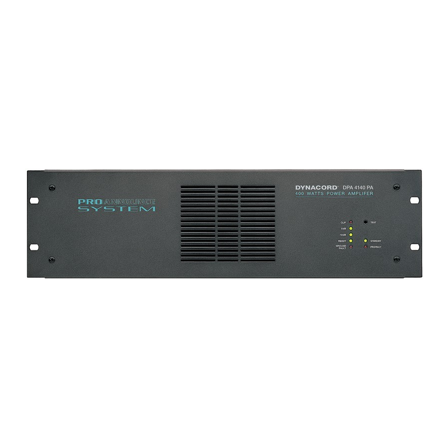
Cable length (m) 21.6 V emergency 24 V supply JY(St)Y 4x2x0,6 4 x DPC 4550 4 x DPC4550 + 4 x DPC4350 JY(St)Y 4x2x0,8 4 x DPC 4550 4 x DPC4550 + 4 x DPC4350 PROMATRIX System Benutzerhandbuch 1.1 5-49... - Page 62 DEVICE DESCRIPTIONS DPA 4000 PROMATRIX Power Amplifier 5.3.1 Characteristics The PROMATRIX system includes four DPA 4000 Series power amplifiers, offering common features as listed below • 4 models: DPA 4410 4 x 100 W DPA 4411 4 x 100 W Remote Control...
- Page 63 The module allows connecting balanced XLR-input and XLR-thru lines as well as connection to the remote control bus of the DPM 4000 (RS-485). Prior to connecting the amplifier to the operating voltage, the unit’s address has to be set using the switches “A” and “B” (A=low value part) PROMATRIX System User Handbook 1.1 5-51...
- Page 64 • TEST-button for installations with emergency switching, RESET for ground fault • LED-meter instrument; indication in the range of –13 dB to 0 dB and CLIP • Mains voltage selector switch 115/230 V AC 5-52 PROMATRIX System User Handbook 1.1...
- Page 65 • Pilot tone detection (all channels) • Ground fault detection (all channels) • Thermal overload amplifier / mains transformer • Configuration • Measured values of current and voltage at the power outputs • Extension-kits PROMATRIX System User Handbook 1.1 5-53...
- Page 66 DCS 400 Control System 5.4.1 Characteristics DCS 400 Series modules increase the PROMATRIX system's control functionality in miscellaneous ways. These printed board assemblies in the Europe standard format are usually inserted at the rear of a PA-system rack-shelf or installed in suitable distribution boxes. The DCS 400 system consists of five different modules and additional extensions: •...
-
Page 67: Installation Note
25 mA .. 65 mA Operating current at 24 V 35 mA Operating temperature range +5° C .. +40° C Dimensions (W x H x D) 160 x 25 x 100 mm Weight 135 g PROMATRIX System User Handbook 1.1 5-55... - Page 68 S2 Watch Reset DPM4000 or DCS401 EPROM SRAM EEPROM DPM4000 or DCS401 RS485 DCS416 DCS401-Address DCS412 INIT Test DCS408/9 LED1 LED2 2 x Rotary Encoder CN12 +24V BLOCKDIAGRAM DCS 401 -24V Jumper CN3, CN5 5-56 PROMATRIX System User Handbook 1.1...
- Page 69 Contact load (ohmic load) 2000 VA Contact current Contact voltage 100 V AC Operating temperature range +5° C .. +40° C Dimensions (W x H x D) 160 x 20 x 100 mm Weight 200 g PROMATRIX System User Handbook 1.1 5-57...
- Page 70 ∅ 4,2 Maximally 12 DCS 408 / DCS 409 modules can be cascaded. Using the insertion bridge CN3, select the connection of the supply voltage (CN1/CN15). BLOCK DIAGRAM DCS 408 CN15 OUTPUT INPUT +24V -24V 5-58 PROMATRIX System User Handbook 1.1...
- Page 71 Contact load (ohmic load) 1 A / 24 V DC Contact current, maximum Operating temperature range +5° C .. +40° C Dimensions (W x H x D) 160 x 17 x 100 mm Weight 155 g PROMATRIX System User Handbook 1.1 5-59...
- Page 72 Maximally 12 DCS 408 / DCS 409 modules can be max ∅ 7,5 ∅ 4,2 cascaded. Using the insertion bridge CN3, select the connection of the supply voltage (CN1/CN15). BLOCK DIAGRAM DCS 409 CN15 OUTPUT INPUT +24V -24V 5-60 PROMATRIX System User Handbook 1.1...
- Page 73 The module is to be mounted on the rear of PA-system rack-shelves or inside of suitable distribution boxes. It is for the connection of control lines, pushbuttons, switches and sensors to be able to evaluate their individual status (ON, OFF) within the PROMATRIX system. Features •...
- Page 74 ∅ 4,2 Maximally 5 DCS 412 modules can be cascaded. Using the insertion bridge CN9, select the connection of the supply voltage (CN8/CN10). BLOCK DIAGRAM DCS 412 CN10 +24V -24V OUTPUT INPUT +24V -24V 5-62 PROMATRIX System User Handbook 1.1...
- Page 75 The module can be mounted on the rear of PA-system rack-shelves or inside of suitable distribution boxes. For once, it serves for connecting analog control lines and potentiometers, with their levels being utilized within the PROMATRIX system installation to control volume controls or other continuous parameters. Additionally, it allows controlling external devices with analog inputs.
- Page 76 ∅ 7,5 ∅ 4,2 Maximally 2 DCS 416 modules can be cascaded. Using the insertion bridge CN8, CN9, select the connection of the supply voltage (CN7/CN10). Board select CN10 OUTPUT INPUT +24V -24V CN13 5-64 PROMATRIX System User Handbook 1.1...
- Page 77 This monitor module (2 HU) is for mounting in PA-system rack-shelves. It is used for acoustically and optically monitoring power amplifier outputs (monitoring) as well as for pre-listening to DPM 4000 input signals in a PROMATRIX system installation. The DCS 401 controller controls the DCS 420. Features •...
-
Page 78: Device Descriptions
1-step monitor source selection 10-step monitor source selection + 24 V - INTERFACE DCS 400 AUDIO INPUT +8 V P / S S / P S / P +5 V Meter KEYS DISPLAY SPEAKER PHONES LEVEL 5-66 PROMATRIX System User Handbook 1.1... - Page 79 DEVICE DESCRIPTIONS 5.4.8 NRS 90240 ROTARY ENCODER Description: The NRS 90240 includes a rotary encoder and connection board with mounting accessories for remotely controlling level controls, delays, and control voltages of a PROMATRIX system. Features: Rotary encoder Connection board Mounting accessories Knob Note: The cover frame needs to be ordered separately.
-
Page 80: Installation Notes
VDE 0100 and EN 60065 regulations. Specifications Operating voltage 24 V DC, -10 / +30% Operating temperature range +5° C ... +40°C Dimensions (W x H x D) 19”, 483 x 88,1 x 336,5mm Weight 5,6 kg 5-68 PROMATRIX System User Handbook 1.1... - Page 81 DEVICE DESCRIPTIONS DCS 4XXR 10 Modules max. 86264 Power +24V LED-gn LED-gn Backplane Active 86253 PROMATRIX System User Handbook 1.1 5-69...
- Page 82 25 mA ... 65 mA Operating current at 24 V 35 mA Operating temperature range +5° C ... +40°C Dimensions (W x H x D) 37.5 x 80.6 x 245 mm Weight 207 g 5-70 PROMATRIX System User Handbook 1.1...
- Page 83 CLK 7 DATA / EN LED gn 86265 2 x Rotary Encoder DCS408R / 409R SHIFT CLK / DATA / EN / RES REGISTER DCS 420 +24V Controller - PCB 86254 DCS 401R BLOCK DIAGRAMM PROMATRIX System User Handbook 1.1 5-71...
- Page 84 Mounting the module and establishing the connections are solely admissible when performed in accordance to VDE 0100 and EN 60065 regulations. Specifications Operating temperature range +5° C .. +40° C Dimensions (W x H x D) 37.5 x 80.6 x 245 mm Weight 115 g 5-72 PROMATRIX System User Handbook 1.1...
- Page 85 DATA3 DATA4_A DATA5 DATA5_A DATA_SEL DATA_SEL_A EN1_A EN2_A EN3_A EN4_A EN5_A EN6_A EN7_A MON+ MON- +24V to DCS 408/409 to DCS 412 to DCS 416/420 to next DCS 400 or to next DCS 400 PROMATRIX System User Handbook 1.1 5-73...
- Page 86 Mounting the module and establishing the connections are solely admissible when performed in accordance to VDE 0100 and EN 60065 regulations. Specifications Dimensions (W x H x D) 37.5 x 80.6 x 245 mm Weight 71 g 5-74 PROMATRIX System User Handbook 1.1...
- Page 87 DEVICE DESCRIPTIONS CLK1 CLK1_A CLK2 CLK2_A CLK3 CLK3_A RES_A *RES *RES_A DATA1_A DATA1 DATA2 DATA2_A DATA3_A DATA3 DATA4_A DATA5 DATA5_A DATA_SEL DATA_SEL_A EN1_A EN2_A EN3_A EN4_A EN5_A EN6_A EN7_A EN8_A MON+ MON- +24V PROMATRIX System User Handbook 1.1 5-75...
- Page 88 37.5 x 80.6 x 245 mm Weight 163 g Relay contacts: Contacts 2 Wechsler / 2 SPDT Contact material AgPd + 10µ Au Contact load (real) 1A / 24V DC 0.5A / 120V AC Contact current max. 5-76 PROMATRIX System User Handbook 1.1...
- Page 89 LK10 LK11 LK16 DATA5 DATA5_A DATA_SEL DATA4_SEL_A EN1_A EN2_A LK12 LK13 LK21 LK22 LK14 LK15 EN3_A EN4_A EN5_A EN6_A EN7_A EN8_A MON+ MON- +24V Signal - Relay - PCB 86257 DCS 407R BLOCK DIAGRAMM PROMATRIX System User Handbook 1.1 5-77...
- Page 90 Dimensions (W x H x D) 37.5 x 80.6 x 245 mm Weight 225 g Relay contacts: Contacts 2 Wechsler / 2 SPDT Contact material AgNi 90/10 Contact load (real) 2000 VA Contact current Switching voltage 100 V AC 5-78 PROMATRIX System User Handbook 1.1...
- Page 91 EN7_A EN8_A BR11 BR12 BR10 +24V EN 3 EN 2 Relay DATA2 Driver DATA1_A CLK1 +24V BR15 BR16 BR14 BR13 DATA5 DATA5_A +24V DATA_SEL DATA_SEL_A EN1_A MON+ MON- 100V-Relay-PCB 86258 DCS 408R BLOCK DIAGRAMM PROMATRIX System User Handbook 1.1 5-79...
- Page 92 Dimensions (W x H x D) 37.5 x 80.6 x 245 mm Weight 185 g Relay contacts: Contacts 2 Wechsler / 2 SPDT Contact material AgPd + 10µ Au Contact load 0.5A / 120V AC Contact current max. 5-80 PROMATRIX System User Handbook 1.1...
- Page 93 EN8_A BR11 BR12 BR10 +24V EN 3 EN 2 Relay DATA2 Driver DATA1_A CLK1 +24V BR15 BR16 BR14 BR13 DATA5 DATA5_A +24V DATA_SEL DATA_SEL_A EN1_A MON+ MON- Control Relay Module DCS 409R BLOCK DIAGRAM PROMATRIX System User Handbook 1.1 5-81...
- Page 94 Input voltage for on (High) > ±10 V Input current at U = 24 V = 4.8 mA Input voltage max. = ±31 V IN max Output source 24V: Output current max. 90 mA 5-82 PROMATRIX System User Handbook 1.1...
- Page 95 BR13 BR11 Input 10 BR10 EN1_A Input 9 DATA_A CLK1_A Input 8 Input 7 Input 6 Input 5 Input 4 DATA1 CLK1 Input 3 +24V Input 2 Input 1 Logic-Input-PCB DCS 412R BLOCK DIAGRAMM PROMATRIX System User Handbook 1.1 5-83...
- Page 96 Voltage range (min. .. max.) 0 V..10 V DC Output impedance 47 Ohm Maximum load 2 kOhm Reference voltage source: Output voltage 10 V DC Maximum output current 30 mA Resolution Input and Output signals 8 Bit 5-84 PROMATRIX System User Handbook 1.1...
- Page 97 DAT PCB SEL Ident RES PCB SEL EN DAC Input 1 0...10V DATA AD/DA EN ADC +18V DATA ADC Input 8 +24V 0...10V +24V -24V +18V +24V Analog I/O Module DCS 416R BLOCK DIAGRAM PROMATRIX System User Handbook 1.1 5-85...
-
Page 98: Device Descriptions
31 mA ... 40 mA Operating Current at 24 V 35 mA Operating Temperature Range +5° C ... +40°C Dimensions (W x H x D) 37.5 x 80.6 x 245 mm Weight 187 g 5-86 PROMATRIX System User Handbook 1.2... - Page 99 INIT ACTIVE Test LED rd LED ye 86285.8 CLK 7 DATA / EN LED gn N.C. CLK / DATA / EN / RES N.C. N.C. +24V Control Module DCS 421R 359 048 BLOCK DIAGRAM PROMATRIX System User Handbook 1.2 5-87...
- Page 100 GND 3 OUT 4 - INP 4 - OUT 4 + INP 4 + GND 4 GND 4 OUT SPARE - IN/OUT CC OUT SPARE + IN/OUT CC GND SPARE GND CC O U T 5-88 PROMATRIX System User Handbook 1.2...
-
Page 101: Control Indicators
Allows cascading the LF-signal for the spare amp via several DCS 422R modules. The INPUT / OUTPUT with a sensitivity of 590 mV into 600 ohms is unbalanced. Block Diagram A block diagram of the modules DCS 422R and DCS 423R can be found on page 5-93. PROMATRIX System User Handbook 1.2 5-89... - Page 102 INP 4- OUT 4+ OUT 4- Fault Amp 4 N.C. Input Spare + Input Spare - Output Spare + Output Spare - Fault AMP Spare Collecting Fault Signal - A - - B - 100V-Inputs 5-90 PROMATRIX System User Handbook 1.2...
- Page 103 COLLECTING FAULT SIGNAL is a collective fault-message, i.e. the CFS-output is active when one of the four monitored power amps fails to operate. The output can be operated with a max. power rating of 200 mA against +24V. PROMATRIX System User Handbook 1.2 5-91...
- Page 104 86279 (insert the jumper only in one pin of the 2-pole bridging strip). This sets the pilot tone recognition for all unused channels permanently to “OK”. Block Diagram A block diagram of the modules DCS 422R and DCS 423R can be found on page 5-93. 5-92 PROMATRIX System User Handbook 1.2...
- Page 105 P/S - S/P DCS 421R P/S - S/P DC -Input DC -Input +24V +15V +24V +15V PILOT TON E SPA RE A M PLIFIER SWITCH IN G BLOCK DIA G RA M 359049 DCS 422R/DCS 423R PROMATRIX System User Handbook 1.2 5-93...
- Page 106 The entire system is not functional if one module fails to operate properly. If one spare system has been switched off because of hardware limitations, all subsequent spare systems up to the eighth system are also not operational. 5-94 PROMATRIX System User Handbook 1.2...
- Page 107 DCS 422R / 423R modules. It is possible to configure up to eight identical spare systems this way. The DCS 421R control module also provides the possibility to use mixed configurations. Please contact our technical support if your interested in further details. PROMATRIX System User Handbook 1.2 5-95...
-
Page 108: Single-Channel Configuration
The following table shows a listing of needed modules for the design of different spare systems in single-channel configuration. DCS 421R SPARE AMP`s SETUP AMP´s 405R 421R 422R 423R Max.64 Max.60 3-12 Max.56 4-16 Max.52 5-96 PROMATRIX System User Handbook 1.2... -
Page 109: Multi-Channel Configuration
The following table shows a listing of needed modules for the design of different spare systems in multi-channel configuration. DCS 421R SPARE AMPs SETUP AMPs 405R 421R 422R 423R Max. 32 Max. 32 3-12 Max. 24 4-16 Max. 16 PROMATRIX System User Handbook 1.2 5-97... - Page 110 The following table shows a listing of needed modules for the configuration of different spare systems using an externally generated pilot tone signal. DCS 421R SPARE AMPs SETUP AMPs 405R 421R 422R 423R Max. Max. 3-12 Max.68 4-16 Max. 5-98 PROMATRIX System User Handbook 1.2...
- Page 111 Opposed to that, the CFS-contact is connected to ground potential (spare system o.k.) when in inactive state, while it is open on the occurrence of a “spare system fault”. As a result, an error status will also be signaled during total system power loss, which satisfies the rules of fail-safety. PROMATRIX System User Handbook 1.2 5-99...
-
Page 112: Configuration Examples
Spare Pilot Tone Pilot 19kHz Detector Prog A Pilot Detector Prog A Pilot Detector Prog A Pilot Detector Prog A Pilot Detector Pilot Detector DCS 421R SPARE AMPs SETUP AMPs 405R 421R 422R 423R 5-100 PROMATRIX System User Handbook 1.2... - Page 113 Prog B Prog D Prog B Prog D Prog B Prog D Prog B Prog D Prog B Prog D Prog B Prog D DCS 421R SPARE AMPs SETUP AMPs 405R 421R 422R 423R PROMATRIX System User Handbook 1.2 5-101...
- Page 114 Detector Prog F Prog F Pilot Detector Prog G Prog G Pilot Detector Prog H Prog H Pilot Detector Pilot Tone 19kHz Pilot Detector DCS 421R SPARE AMPs SETUP AMPs 405R 421R 422R 423R 5-102 PROMATRIX System User Handbook 1.2...
- Page 115 Prog F Prog F Pilot Detector Prog G Prog G Pilot Detector Prog H Prog H Pilot Detector Spare Pilot Tone 19kHz Pilot Detector DCS 421R SPARE AMPs SETUP AMPs 405R 421R 422R 423R PROMATRIX System User Handbook 1.2 5-103...
- Page 116 P ro g V P ro g W P ro g W P ro g X P ro g X IS P O S P DCS 421R SPARE AMPs SETUP AMPs 405R 421R 422R 423R 5-104 PROMATRIX System User Handbook 1.2...
- Page 117 Prog S Prog S Prog T Prog T Prog U Prog U Prog V Prog V Prog W Prog W Prog X Prog X DCS 421R SPARE AMPs SETUP AMPs 405R 421R 422R 423R PROMATRIX System User Handbook 1.2 5-105...
- Page 118 P ro g V P ro g W P ro g W P ro g X P ro g X IS P O S P DCS 421R SPARE AMPs SETUP AMPs 405R 421R 422R 423R 5-106 PROMATRIX System User Handbook 1.2...
- Page 119 Prog A Pilot Detector Spare Pilot Detector Prog A Pilot Detector Prog A Pilot Detector Prog A Pilot Detector Prog A Pilot Detector Pilot Detector DCS 421R SPARE AMPs SETUP AMPs 405R 421R 422R 423R PROMATRIX System User Handbook 1.2 5-107...
- Page 120 Prog B Prog D Prog B Prog D Prog B Prog D Prog B Prog D Prog B Prog D Prog B Prog D DCS 421R SPARE AMPs SETUP AMPs 405R 421R 422R 423R 5-108 PROMATRIX System User Handbook 1.2...
- Page 121 DCS 416 1 - 8 1 - 8 DCS 416 9 - 16 9 - 16 è Connect the control module DCS 401 via RJ-45 cable to the REMOTE CONTROL socket on the DPM 4000. PROMATRIX System User Handbook 1.1...
- Page 122 DCS 401 control modules installed in the system. All components sharing the network are listed in the component list. This procedure takes approximately 20 seconds. Afterwards, the system is ready for operation. PROMATRIX System User Handbook 1.1...
- Page 123 DMM 4650 sequence is possible as well. Programming examples for interconnecting the DMM 4650 are provided in the file Demo99_2.pmx, which is installed during the installation of the PROMATRIX Designer software within the following directory: /promatrix/examples/. PROMATRIX System User Handbook 1.1...
- Page 124 6.3 NRS 90226 Adapter Printed Board Assembly Adapter printed board assembly for connecting RJ45 lines and single conductors to be used with paging consoles, I/O-lines (slot 5), remote lines (DCS), and monitoring. characteristics: 2 x RJ-45 sockets, 8-pole binding post. PROMATRIX System User Handbook 1.1...
Need help?
Do you have a question about the PROMATRIX System and is the answer not in the manual?
Questions and answers