Table of Contents
Advertisement
Quick Links
Download this manual
See also:
Owner's Manual
Advertisement
Table of Contents

Related Manuals for Dynacord DPM 8016


Summary of Contents for Dynacord DPM 8016
- Page 1 DPM 8016 en | Operation manual...
-
Page 3: Table Of Contents
DPM 8016 Table of Contents | en Table of contents Safety notes Brief description System description Scope of delivery and warranty Installation Front Back Installation Connections Power supply voltage Ethernet REMOTE CAN BUS Control port Configuration Installing extension cards Network configuration... -
Page 4: Safety Notes
| Safety notes DPM 8016 Safety notes Danger! The lightning symbol inside a triangle notifies the user of high-voltage, uninsulated lines and contacts inside the devices that could result in fatal electrocution if touched. Warning! An exclamation mark inside a triangle refers the user to important operating and service instructions in the documentation for the equipment. - Page 5 DPM 8016 Safety notes | en 14. Please ensure that no dripping water or spray can penetrate the inside of the device. Do not place any objects filled with fluids, such as vases or drinking vessels, on top of the device.
- Page 6 | Safety notes DPM 8016 Caution! Risk of explosion if battery is not replaced correctly. Must be replaced only with the same or equivalent type of battery. 16-Dec-13 | 02 | F01U259190 Operation manual...
-
Page 7: Brief Description
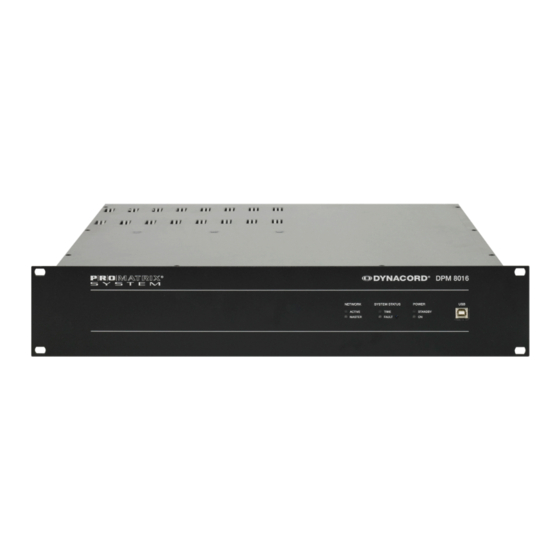
PROMATRIX 8000 system. A single DPM 8016 can manage up to 16 call stations and up to 500 loudspeaker circuits; in larger systems, up to ten DPM 8016 controllers can be linked with each other via a digital audio and control bus. -
Page 8: System Description
A single DPM 8016 can manage up to 16 call stations and up to 500 zones; in larger systems, up to 10 DPM 8016 controllers can be linked with each other via a digital audio and control bus. Control inputs and outputs can be... - Page 9 Audio routing A digital 36 x 16 audio matrix is integrated into the DPM 8016. Up to 16 local audio inputs, 4 internal generators, and 16 optional CobraNet network inputs are available. The 16 matrix outputs can be used as local audio outputs, or optionally provided via the CobraNet network.
- Page 10 The PROMATRIX 8000 system also supports emergency power operation – in the event of a power failure, the DPM 8016 can assume all power management functions, that is, all unnecessary internal and external consumers switch to standby mode, or are deactivated and only reactivated again when required.
- Page 11 DPM 8016 for batch messages. Operating Instructions In accordance with the specified and technical details for this product, the DPM 8016 can be used to control and monitor public address and call systems within the building installation, as well as for professional audio systems.
-
Page 12: Scope Of Delivery And Warranty
2-pole connector for 24 V DC input (Phoenix PC 5/2-STF1-7.62 – 1777833) 12-pole connector for GPIO (Phoenix MC 1.5/12-STF-3.81 – 1827800) Warranty card with safety notes Table 4.1: Scope of delivery Warranty For information regarding the warranty, see www.dynacord.com 16-Dec-13 | 02 | F01U259190 Operation manual... -
Page 13: Installation
FAULT LED This LED illuminates yellow during a reset or in the event of a watchdog error in the DPM 8016. It also indicates faults in external system components (end levels, call stations, relay cards, etc.). The LED is... -
Page 14: Back
DPM 8016 is disconnected from the voltage supply or if the voltage supply is switched off or fails. USB interface Used to connect the DPM 8016 to a PC. For future applications. See the Section Connections, page 17 Back Figure 5.1:... -
Page 15: Installation
Installation The DPM 8016 has been developed for horizontal installation in a conventional 19" rack cabinet. As a rule, the DPM 8016 must be mounted in such a way that the ventilation slots are not blocked on either side. Figure 5.2: Air supply and ventilation of the DPM 8016 The ventilation direction runs from left to right when the device is observed from the front. - Page 16 | Installation DPM 8016 Figure 5.3: Attachment on the front panel When installing in cabinet racks, installation rails should always be used to prevent the front panel distorting. 16-Dec-13 | 02 | F01U259190 Operation manual...
-
Page 17: Connections
(AWG16) can be used. Recommended connecting line: Symmetrical cable configuration with flexible 2 x 0.14 mm² shielding. Although all analog inputs and outputs of the DPM 8016 can also have asymmetrical configurations, a symmetrical audio connection cable is a better alternative. -
Page 18: Power Supply Voltage
Power supply voltage The DPM 8016 requires a DC 24 V voltage supply. The scope of delivery includes a 2-pole connector. Conductor cross-sections of 0.2 mm² (AWG24) to 6 mm² (AWG10) can be used. Recommended connecting cable: Flexible CU strand, LiY, 1.5 mm². -
Page 19: Remote Can Bus
T568B is more widely used. LED status lights The Ethernet interface of the DPM 8016 controller has an orange and a green LED to display the status of the Ethernet connection. If no network cable is connected, both LEDs remain unlit. - Page 20 | Connections DPM 8016 Data rate (in kbit/s) Bus length (in meters) 62.5 1000 2500 5000 Table 6.2: Data rate and bus length of the REMOTE CAN BUS The following diagrams show the assignment of the CAN jack / CAN connector.
- Page 21 DPM 8016 Connections | en Bus length (in Data transmission cable Connection Maximum data resistance (in transmission Resistance per unit Cable cross- mΩ) rate (in mΩ/m) section 0 to 40 < 70 0.25 to 0.34 mm² 1000 kbit/s at AWG23, AWG22...
-
Page 22: Control Port
DPM 8016 Control port The control port on the rear of the DPM 8016 controller is split into two halves. The upper half has eight freely configurable control inputs, and a DCF77 receiver can also be connected. The lower half has six freely configurable control outputs and a ready contact, and slave clocks can also be connected. - Page 23 To operate the externally connected elements, a voltage source is available on the connection 24/48V/200mA; see also the following diagram. Notice! The voltage value used as the supply voltage for the DPM 8016 controller is always present on the 24/48V output. Caution! The maximum permissible power on the 24/48V output is 200 mA.
- Page 24 Net software allows the user to configure the fault types for which the changeover contact should switch over and signal the status “Not ready”. To integrate the DPM 8016 into the hazard alert systems, a normally-closed contact (standby current principle) is recommended, i.e., the left and middle pin.
-
Page 25: Configuration
For precise installation instructions, see the description of the respective module. Extension slots Eight slots, which are numbered 1 through 8, are available on the rear panel of the DPM 8016 for extending the system. These slots allow any combination of extension cards of the following types: •... -
Page 26: Network Configuration
Figure 7.1: Installation of an audio extension card Network module slot The network module slot on the rear panel of the DPM 8016 can be used to retrofit an audio network interface to a CobraNet network. The CM-1 module used here has two Ethernet connections to set up a redundant network. - Page 27 ID 192.168.1 can be retained, and • no other device has the host ID 100. If at least one of these three conditions is not met, the default IP address of the DPM 8016 must be changed. Example: The following diagram shows a sample application with four DPM 8016 controllers in a connected Ethernet.
-
Page 28: Operation
| Operation DPM 8016 Operation To operate the DPM 8016, see the IRIS-Net documentation. 16-Dec-13 | 02 | F01U259190 Operation manual... -
Page 29: Maintenance
DPM 8016 Maintenance | en Maintenance The DPM 8016 does not require any maintenance. Operation manual 16-Dec-13 | 02 | F01U259190... -
Page 30: Technical Data
See technical specifications of used output module Frequency response 20 Hz to 20 kHz (-0.5 dB) Signal to noise ratio (A-weighted) DPM 8016 analog in to analog out: 106 dB typical THD+N < 0.01% Crosstalk < 100 dB @ 1 kHz... -
Page 31: Power Consumption
Dimensions (W x H x D) 19”, 2 HU, 483 x 88 x 376 mm Weight DPM 8016 (without optional modules): 7.25 kg DPM UI-1 Universal Input Module: 100 g DPM AO-1 Analog Output Module: 100 g PMX-MM-2 Message Manager Module: 85 g... - Page 32 0.060 A 0.170 A mode (-3 dB) Table 10.1: DPM 8016 power consumption at 24 V DC Power consumption of call stations For each DPC 8015 call station: 0.080 A (with active loudspeaker: 0.190 A) For each DPC 8120 call station extension: 0.020 A...
-
Page 33: Block Diagram
DPM 8016 Technical data | en 10.2 Block diagram AUDIO AUDIO NETWORK MODULES MODULES 2 - 8 Channels Analog I/O 16 Inputs / 16 Outputs Digital I/O AUDIO AUDIO AUDIO AUDIO AUDIO AUDIO AUDIO AUDIO SLOT 4 SLOT 1 SLOT 2... -
Page 34: Dimensions
| Technical data DPM 8016 10.3 Dimensions 10.4 Standards The DPM 8016 meets the following standards (correct as of July 2012): • EN 54-16 • EN 55103-1 • EN 55103-2 • EN 55022 • EN 55024 • EN 60945... -
Page 35: Appendix
Different network protocols can be used for communication between the devices connected to the Ethernet. The DPM 8016 uses the TCP/IP protocol, which means this is an IP network. In an IP network, IP addresses are used for the logical address assignment of devices. The DPM 8016 uses version IPv4 (Internet Protocol Version 4) for address assignment, which means an IP address is 32 bits (= 4 bytes) long. - Page 36 | Appendix DPM 8016 correspond to the suffix /24, because with the subnet mask 255.255.255.0, the first 24 places of an IP address are selected as the network address (binary format). The choice of subnet mask and the resulting different split of the IP address into network element and host element have an effect on the maximum number of addressable devices within a network.
-
Page 37: Table Of Ip Addresses
DPM 8016 Appendix | en 11.2 Table of IP addresses Project: ________________________________________ Subnet mask Gateway Device Name in IRIS-Net Location/Description IP address Operation manual 16-Dec-13 | 02 | F01U259190... - Page 40 Bosch Sicherheitssysteme GmbH Robert-Bosch-Ring 5 85630 Grasbrunn Germany www.dynacord.com © Bosch Sicherheitssysteme GmbH, 2013...
Need help?
Do you have a question about the DPM 8016 and is the answer not in the manual?
Questions and answers