Table of Contents
Advertisement
Quick Links
Advertisement
Table of Contents

Subscribe to Our Youtube Channel
Related Manuals for AXIOMTEK tBOX321-870-FL Series


Summary of Contents for AXIOMTEK tBOX321-870-FL Series
- Page 1 Series Embedded System User’s Manual...
-
Page 2: Disclaimers
Axiomtek does not make any commitment to update the information in this manual. Axiomtek reserves the right to change or revise this document and/or product at any time without notice. No part of this document may be reproduced, stored in a retrieval system, or transmitted, in any form or by any means, electronic, mechanical, photocopying, recording, or otherwise, without the prior written permission of Axiomtek Co., Ltd. -
Page 3: Safety Precautions
Safety Precautions Before getting started, please read the following important safety precautions. User should not modify any unmentioned jumper setting without Axiomtek FAE’s instruction. Any modification without instruction might cause system to become damage The tBOX321-870-FL does not come equipped with an operating system. An operating system must be loaded first before installing any software into the computer. -
Page 4: Classification
Classification Degree of production against electric shock: not classified Degree of protection against the ingress of water: IP40 Equipment not suitable for use in the presence of a flammable anesthetic mixture with air or with oxygen or nitrous oxide. Mode of operation: Continuous General Cleaning Tips You may need the following precautions before you begin to clean the computer. - Page 5 Cleaning Tools: Although many companies have created products to help improve the process of cleaning your computer and peripherals users can also use household items to clean their computers and peripherals. Below is a listing of items you may need or want to use while cleaning your computer or computer peripherals.
- Page 6 If the computer equipments need the maintenance or are beyond repair, we strongly recommended that you should inform your Axiomtek distributor as soon as possible for the suitable solution. For the computers that are no longer useful or no longer working well, please contact your Axiomtek distributor for recycling and we will make the proper arrangement.
-
Page 7: Table Of Contents
Table of Contents Disclaimers ......................ii Safety Precautions ....................iii Classification ......................iv CHAPTER 1 INTRODUCTION ................1 General Description ................1 System Specifications ................ 2 1.2.1 CPU ........................2 1.2.2 System I/O ......................2 1.2.3 System Specification ..................2 1.2.4 Driver CD Content ..................... - Page 8 This page is intentionally left blank. viii...
-
Page 9: Chapter 1 Introduction
Series User’s Manual CHAPTER 1 INTRODUCTION This chapter contains general information and detailed specifications of the tBOX321-870-FL. The Chapter 1 includes the following sections: General Description System Specification Dimensions I/O Outlets Package List General Description ®... -
Page 10: System Specifications
Series User’s Manual System Specifications 1.2.1 Onboard Intel® Core™ i7-3517UE processor (4M Cache, up to 2.8 GHz) Onboard Intel® Core™ i3-3217UE processor (3M Cache, 1.6 GHz) BIOS American Megatrends Inc. BIOS. “Load Optimized Default” to backup customized Setting in the BIOS flash chip to ... -
Page 11: Driver Cd Content
Series User’s Manual Weight 5.06 kg (11.15 lb) without package 6.5 kg (14.33 lb) with package Dimensions 288.5mm(W) x 211.3mm(D) x 85.2mm(H) NOTE: All specifications and images are subject to change without notice. 1.2.4 Driver CD Content ... -
Page 12: Dimensions
Series User’s Manual Dimensions The following diagrams show you dimensions and outlines of the tBOX321-870-FL. Introduction... -
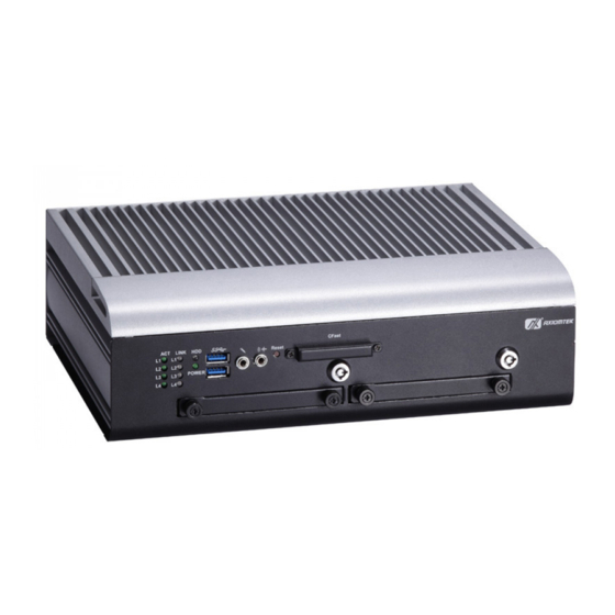
Page 13: I/O Outlets
Series User’s Manual I/O Outlets The following figures show you I/O outlets on front view of the tBOX321-870-FL. Front View Front View drawing Rear View Rear View drawing Introduction... -
Page 14: Packing List
M12 Power cable (optional) M12 Audio cable (optional) M12 Power Adapter (optional) Remote switch cable (optional) Express Mini Card Module (optional) If you can not find this package or any items are missing, please contact Axiomtek distributors immediately. Introduction... -
Page 15: Chapter 2 Hardware Installation
Series User’s Manual CHAPTER 2 HARDWARE INSTALLATION The tBOX321-870-FL is convenient for your various hardware configurations, such as HDD (Hard Disk Drive), CFast card and Express Mini Card. The chapter 2 will show you how to install the hardware. -
Page 16: Installing The Express Mini Card
Series User’s Manual Installing the Express Mini Card Step 1 Turn off the system, and unplug the power cord. Step 2 Turn the system upside down to locate screws at the bottom, loosen screws to remove the bottom cover. -
Page 17: Chapter 3 Jumper Setting & Connector
SBC layout NOTE: We strongly recommended that you should not modify any unmentioned jumper setting without Axiomtek FAE’s instruction. Any modification without instruction might cause system to become damage. Jumper Setting & Connector... -
Page 18: Jumper Setting Summary
Series User’s Manual Jumper Setting Summary Proper jumper settings configure the tBOX321-870-FL to meet your application purpose. We are herewith listing a summary table of all jumpers and default settings for onboard devices, respectively. Description Function Jumper Setting Normal(Default) -
Page 19: Connectors
Series User’s Manual Connectors Connectors connect the CPU card with other parts of the system. Loose or improper connection might cause problems. Make sure all connectors are properly and firmly connected. 3.3.1 VGA & DVI Connector DB15 connector commonly used for the CRT Monitor. -
Page 20: Serial Port Connector
Series User’s Manual 3.3.2 Serial Port Connector The COM1~COM4 Port connector is a standard DB-9 connector.The pin assignment of RS- 232/RS-422/RS-485 is listed on the following table. If you need COM port to support RS-422 or RS-485, please selection to the BIOS items. -
Page 21: Led Indicators
Series User’s Manual 3.3.4 LED Indicators Status\LED ACT( L1~L4) LINK(L1~L4) POWER LAN Linked Bright 100Mbps Blue LED 1000Mbps Yellow LED HDD Active Flash Power on Bright 3.3.5 DC Power Input connector The DC power input connector is M12 A-code Male 5Pin connector... -
Page 22: Digital I/O Connector
Series User’s Manual 3.3.7 Digital I/O Connector The tBOX321-870-FL support an isolated 4-in/4-out Digital I/O (DIO) Signal Signal EXT POWER COM+ OUT0 OUT1 OUT2 OUT3 COM- NOTE: Please refer to Appendix B for more information about Digital I/O 3.3.8... -
Page 23: Pci-Express Mini Card Connector
Series User’s Manual 3.3.9 PCI-Express Mini Card Connector The PCI Express Mini Card connectors with support for a PCI Express x1 link and a USB 2.0 link. A PCI Express Mini Card can be applied to either PCI Express or USB 2.0. -
Page 24: 3.3.10 Cfast™ Socket
Series User’s Manual A PCI Express Mini Card can be applied to either PCI Express or USB 2.0. The USB 2.0 support will be helpful during the transition to PCI Express, because peripheral vendors will need time to design their chipsets to have the PCI Express function. -
Page 25: Usb2.0 M12 Connector
Series User’s Manual 3.3.11 USB2.0 M12 Connector The USB2.0 connector is M12 A-code Male 8Pin connector Signal Signal Shell CHS GND 3.3.12 Audio M12 Connector The Audio connector is M12 D-code Female 5Pin connector Signal Line Out - L... - Page 26 Series User’s Manual This page is intentionally left blank. Jumper Setting & Connector...
-
Page 27: Chapter 4 Ami Bios Setup Utility
Series User’s Manual CHAPTER 4 AMI BIOS SETUP UTILITY This chapter provides users with detailed description about how to set up basic system configuration through the AMI BIOS setup utility. Starting To enter the setup screens, follow the steps below: Turn on the computer and press the <Del>... -
Page 28: Navigation Keys
Series User’s Manual Navigation Keys The BIOS setup/utility uses a key-based navigation system called hot keys. Most of the BIOS setup utility hot keys can be used at any time during the setup navigation process. These keys include <F1>, <F10>, <Enter>, <ESC>, <Arrow> keys, and so on. -
Page 29: Main Menu
Series User’s Manual Main Menu System Time/Date Use this option to change the system time and date. Highlight System Time or System Date using the <Arrow> keys. Enter new values through the keyboard. Press the <Tab> key or the <Arrow>... -
Page 30: Advanced Menu
Series User’s Manual Advanced Menu The Advanced menu allows users to set configuration of the CPU and other system devices. You can select any of the items in the left frame of the screen to go to the sub menus: ►... - Page 31 Series User’s Manual ACPI Settings You can use this screen to select options for the ACPI Configuration, and change the value of the selected option. A description of the selected item appears on the right side of the screen.
- Page 32 Series User’s Manual S5 RTC Wake Settings Use this option to wake on the system on the setting time. When enabled System will wake on the time specified. CPU Configuration This screen shows the CPU Configuration. AMI BIOS Setup Utility...
- Page 33 Series User’s Manual SATA Configuration You can use this screen to select options for the SATA Configuration, and change the value of the selected option. SATA Controller(S) Use this item to enable or disable the integrated SATA controllers. (Default: Enabled) ...
- Page 34 Series User’s Manual PCH-FW Configuration You can use this screen to confirm ME Firmware version. USB Configuration You can use this screen to select options for the USB Configuration, and change the value of the selected option. Legacy USB Support This is for supporting USB device under legacy OS such DOS, when choosing AUTO”, the system will automatically detect any USB device is plugged into the...
- Page 35 Series User’s Manual AMI BIOS Setup Utility...
- Page 36 Series User’s Manual NCT6106D Super IO Configuration Use this screen to select options for the Super IO Configuration, and change the value of the selected option Serial Port 0-3 configuration 1. Serial port: This option used to enable or disable the serial port.
- Page 37 Series User’s Manual AMI BIOS Setup Utility...
- Page 38 Series User’s Manual NCT6106D H/W Monitor This screen shows the Hardware Health Configuration. WatchDog Configuration After the system stops working for a while, it can be auto-reset by the Watchdog Timer. The integrated Watchdog Timer can be set up in the system reset mode by this option.
-
Page 39: Chipset Menu
Series User’s Manual Chipset Menu The Chipset menu allows users to change the advanced chipset settings. PCH-IO Configuration This screen shows the Chipset Configuration AMI BIOS Setup Utility... - Page 40 Series User’s Manual System Agent (SA) Configuration 1. Graphics Configuration This option allows users to change the integrated graphic device settings. Primary IGFX Boot Display Select the video device which will be activated during POST. DVMT Pre-Allocated Pre-allocated memory is the small amount of system memory made available at boot time by the system BIOS for video.
- Page 41 Series User’s Manual 2. Memory Configuration This screen shows the memory information. AMI BIOS Setup Utility...
-
Page 42: Boot Menu
Series User’s Manual Boot Menu The Boot menu allows users to change boot options of the system. You can select any of the items in the left frame of the screen to go to the sub menus: Setup Prompt Timeout Set the Timeout for wait press key to enter Setup Menu ... -
Page 43: Security Menu
Series User’s Manual Security Menu The Security menu allows users to change the security settings for the system. Supervisor Password This item indicates whether a supervisor password has been set. If the password has been installed,『 Installed』 displays. If not, 『Not Installed』displays. -
Page 44: Save & Exit Menu
Series User’s Manual Save & Exit Menu The Exit menu allows users to load the system configuration with optimal or failsafe default values. Save Changes and Exit When you have completed the system configuration changes, select this option to leave Setup and reboot the computer so the new system configuration parameters can take effect. -
Page 45: Appendix Awatchdog Timer
Series User’s Manual APPENDIX A WATCHDOG TIMER What is Watchdog Timer The integrated W atchdog Timer can be set up by programming. There are 1~255 levels available. As long as the vaule of timer is set, after enabling, the countdown of the value is starting. - Page 46 Series User’s Manual Sample of Watchdog application Assume there is program A which needs to maintain running in a system. T he value of W atchdog Timer must be set bigger than the running time of program A. Then, after the running time of program A is finished, either to disable or to reset watchdog timer.
-
Page 47: Appendix Bdigital I/O
Series User’s Manual APPENDIX B DIGITAL I/O Digital I/O Specification Digital Input: Input channels: 4, sink/source type Input voltage: 0 to 30VDC at 25Hz Input level for dry contacts: Logic level 0: close to ground Logic level 1: open Input level for wet contacts: Logic level 1: +/-3VDC max. - Page 48 Series User’s Manual Digital Input Wiring DRY contact Logic level 0: close to ground Logic level 1: open EXT_POWER XIN1 XIN2 XIN3 XIN4 DIO_GND WET contact Logic level 1: +/-3VDC max. Logic level 0: +/- 10VDC min. to +/-30VDC max...
Need help?
Do you have a question about the tBOX321-870-FL Series and is the answer not in the manual?
Questions and answers