Table of Contents
Advertisement
Quick Links
Advertisement
Table of Contents

Related Manuals for AXIOMTEK tBOX323-835-FL Series


Summary of Contents for AXIOMTEK tBOX323-835-FL Series
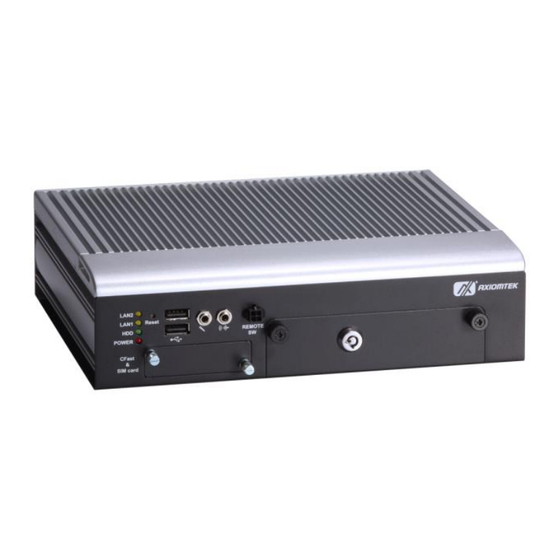
- Page 1 Series Embedded System User’s Manual...
-
Page 2: Disclaimers
Axiomtek does not make any commitment to update the information in this manual. Axiomtek reserves the right to change or revise this document and/or product at any time without notice. No part of this document may be reproduced, stored in a retrieval system, or transmitted, in any form or by any means, electronic, mechanical, photocopying, recording, or otherwise, without the prior written permission of Axiomtek Co., Ltd. -
Page 3: Safety Precautions
Safety Precautions Before you begin, please review these crucial safety precautions: User should not modify any unmentioned jumper setting without Axiomtek FAE’s instruction. Any modification without instruction might cause system to become damage The tBOX323-835-FL does not come with an operating system pre-installed.. -
Page 4: Classification
CAUTION A risk of explosion may occur if the battery is replaced by an incorrect type. Dispose of used batteries according to the instructions. WARNING ⚫ Do not touch the hot surface of the system unit when it is turned on. ⚫... - Page 5 Cleaning Tools: While various companies offer specialized products to facilitate the cleaning process for computers and peripherals, users can also utilize common household items. Below is a list of recommended items for cleaning your computer and its peripherals. Please note that certain components may necessitate the use of specific cleaning products.
- Page 6 Trademarks Acknowledgments Axiomtek is a trademark of Axiomtek Co., Ltd. IBM, PC/AT, PS/2, VGA are trademarks of International Business Machines Corporation. ®...
-
Page 7: Table Of Contents
Table of Contents Disclaimers ......................ii Safety Precautions ....................iii Classification ......................iv SECTION 1 INTRODUCTION................. 1 General Description ................1 System Specifications ............... 2 1.2.1 CPU ........................2 1.2.2 System I/O ......................2 1.2.3 System Specification ..................2 1.2.4 Driver CD Content .................... - Page 8 How to Use the Watchdog Timer ..............35 APPENDIX B DIGITAL I/O ................37 Digital I/O Specification ................... 37 Digital I/O Software Programming ..............37 viii...
-
Page 9: Section 1 Introduction
Series User’s Manual SECTION 1 INTRODUCTION This chapter contains general information and detailed specifications of the tBOX323-835-FL. The Chapter 1 includes the following sections: ◼ General Description ◼ System Specifications ◼ Dimensions ◼ I/O Outlets ◼ Package List General Description ®... -
Page 10: System Specifications
Series User’s Manual System Specifications 1.2.1 ⚫ ◼ Onboard Intel® Atom™ E3845 processor (2M Cache, 1.91 GHz) ⚫ BIOS ◼ American Megatrends Inc. BIOS. “Load Optimized Default” to backup customized Setting in the BIOS flash chip to ◼ prevent from CMOS battery fail ⚫... -
Page 11: Driver Cd Content
Series User’s Manual ⚫ Weight ◼ 3 kg (6.61 lb) without package ◼ 3.8 kg (8.37 lb) with package ⚫ Dimensions ◼ 244mm(W) x 180.5mm(D) x 65.1mm(H) NOTE: All specifications and images are subject to change without notice. 1.2.4 Driver CD Content ⚫... -
Page 12: Dimensions
Series User’s Manual Dimensions The following diagrams show you dimensions and outlines of the tBOX323-835-FL. Introduction... -
Page 13: I/O Outlets
Series User’s Manual I/O Outlets The following figures show you I/O outlets on front view of the tBOX323-835-FL. ⚫ Front View ⚫ Front View drawing ⚫ Rear View ⚫ Rear View drawing Introduction... -
Page 14: Packing List
M12 LAN cable (optional) ⚫ M12 Power cable (optional) ⚫ M12 Power Adapter (optional) ⚫ Remote switch cable (optional) ⚫ Express Mini Card Module (optional) If you can not find this package or any items are missing, please contact Axiomtek distributors immediately. Introduction... -
Page 15: Section 2 Hardware Installation
Series User’s Manual SECTION 2 HARDWARE INSTALLATION The tBOX323-835-FL is convenient for your various hardware configurations, such as HDD (Hard Disk Drive), CFast card and Express Mini Card. The chapter 2 will show you how to install the hardware. -
Page 16: Installing The Express Mini Card And Sim Card
Series User’s Manual Installing the Express Mini Card and SIM card Step 1 Turn off the system, and unplug the power cord. Step 2 Turn the system upside down to locate screws at the bottom, loosen screws to remove the bottom cover. -
Page 17: Installing Hdmi Bracket
Series User’s Manual Installing HDMI bracket Step 1 Fasten the bracket at the position as shown. Step 2 Connect HDMI cable and tied on bracket by cable tie as shown. Hardware Installation... - Page 18 Series User’s Manual This page is intentionally left blank. Hardware Installation...
-
Page 19: Section 3 Jumper Setting & Connector
Series User’s Manual SECTION 3 JUMPER SETTING & CONNECTOR mSATA/CFast Setting Step 1 Turn off the system, and unplug the power cord. Step 2 Turn the system upside down to locate screws at the bottom, loosen screws to remove the bottom cover. -
Page 20: Connectors
Series User’s Manual Connectors Connectors connect the CPU card with other parts of the system. Loose or improper connection might cause problems. Make sure all connectors are properly and firmly connected. 3.2.1 VGA Connector DB15 connector is commonly used for the CRT monitor. -
Page 21: Serial Port Connector
Series User’s Manual 3.3.3 Serial Port Connector The COM1~COM4 Port connector is a terminal block. The pin assignment of RS- 232(4pin)/422/RS-485 is listed on the following table. If you need COM port to support RS- 232(4pin)/422 or RS-485, please selection to the BIOS items. -
Page 22: Usb2.0 Stack Ports
Series User’s Manual 3.3.4 USB2.0 Stack Ports Signal USB Port 0 Signal USB Port 6 USB VCC USB VCC (+5V level) (+5V level) USB #0_D- USB #6_D- USB #0_D+ USB #6_D+ Ground (GND) Ground (GND) 3.3.5 LED Indicators LED Indicator... -
Page 23: M12 Lan Connector (Lan1,2)
Series User’s Manual 3.3.7 M12 LAN Connector (LAN1,2) The M12-8pin LAN Connector is A-Code type which can support 10/100/1000 Mbps 10/100 Mbps 1000 Mbps MDI 2+ MDI 3+ MDI 3- TX - MDI 0- RX + MDI 1+ TX +... -
Page 24: Sim Card Connector
Series User’s Manual 3.3.9 SIM Card Connector The SIM Card slot is a ISO 7816 standard 6-pin connector for PCI Express Mini Card used. Signal SIM_PWR LOCK SIM_RESET SIM_CLK OPEN SIM_VPP SIM_DATA Jumper Setting & Connector... -
Page 25: Pci-Express Mini Card Connector
Series User’s Manual 3.3.10 PCI-Express Mini Card Connector The PCI Express Mini Card connector supports for a PCI Express x1 link and a USB 2.0 link. A PCI Express Mini Card can be applied to either PCI Express or USB 2.0. The USB 2.0 support will be helpful during the transition to PCI Express, because peripheral vendors will need time to design their chipsets to have the PCI Express function. -
Page 26: Cfast™ Socket
Series User’s Manual A PCI Express Mini Card can be applied to either PCI Express or USB 2.0. The USB 2.0 support will be helpful during the transition to PCI Express, because peripheral vendors will need time to design their chipsets to have the PCI Express function. During the transition, PCI Express Mini Cards can be quickly implemented by using USB 2.0. -
Page 27: Serial Port Connector
Series User’s Manual 3.2.12 Serial Port Connector The COM port connector is a terminal block. The pin assignment of RS-232 is listed on the following table. RS-232 DCD, Data carrier detect RXD, Receive data TXD, Transmit data DTR, Data terminal ready... -
Page 28: Hdmi Conncetor
Series User’s Manual 3.2.14 HDMI Conncetor HDMI connector is commonly used for the display. Description Description TMDS data 2+ TMDS clock shield TMDS data 2 shield TMDS clock- TMDS data 2- TMDS data 1+ No connected TMDS data 1 shield... -
Page 29: Section 4 Ami Bios Setup Utility
Series User’s Manual SECTION 4 AMI BIOS SETUP UTILITY This chapter provides users with detailed description about how to set up basic system configuration through the AMI BIOS setup utility. Starting To enter the setup screens, follow the steps below: Turn on the computer and press the <Del>... -
Page 30: Navigation Keys
Series User’s Manual Navigation Keys The BIOS setup/utility uses a key-based navigation system called hot keys. Most of the BIOS setup utility hot keys can be used at any time during the setup navigation process. These keys include <F1>, <F10>, <Enter>, <ESC>, <Arrow> keys, and so on. -
Page 31: Main Menu
Series User’s Manual Main Menu ➢ System Time/Date Use this option to change the system time and date. Highlight System Time or System Date using the <Arrow> keys. Enter new values through the keyboard. Press the <Tab> key or the <Arrow>... -
Page 32: Advanced Menu
Series User’s Manual Advanced Menu The Advanced menu allows users to set configuration of the CPU and other system devices. You can select any of the items in the left frame of the screen to go to the sub menus: ►... - Page 33 Series User’s Manual ACPI Settings You can use this screen to select options for the ACPI Configuration, and change the value of the selected option. A description of the selected item appears on the right side of the screen.
- Page 34 Series User’s Manual NCT6106D Super IO Configuration Use this screen to select options for the Super IO Configuration, and change the value of the selected option Serial Port 1-4 configuration 1. Serial port: This option used to enable or disable the serial port.
- Page 35 Series User’s Manual Serial Port 5 configuration This option used to enable or disable the console redirection. Serial Port Console Redirection This option used to setting the console redirection AMI BIOS Setup Utility...
- Page 36 Series User’s Manual NCT6106D H/W Monitor This screen shows the Hardware Health Configuration. CPU Configuration This screen shows the CPU Configuration. AMI BIOS Setup Utility...
- Page 37 Series User’s Manual IDE Configuration You can use this screen to select options for the SATA Configuration, and change the value of the selected option. ➢ SATA Mode Use this item to choose the SATA operation mode. Here are the options for your selection, IDE Mode, AHCI Mode.
-
Page 38: Chipset Menu
Series User’s Manual Chipset Menu The Chipset menu allows users to change the advanced chipset settings. ➢ USB Configuration This screen shows the Chipset Configuration AMI BIOS Setup Utility... -
Page 39: Boot Menu
Series User’s Manual Boot Menu The Boot menu allows users to change boot options of the system. You can select any of the items in the left frame of the screen to go to the sub menus: ➢ Setup Prompt Timeout Set the Timeout for wait press key to enter Setup Menu ➢... -
Page 40: Security Menu
Series User’s Manual Security Menu The Security menu allows users to change the security settings for the system. ➢ Administrator Password This item indicates whether a supervisor password has been set. If the password has been installed,『 Installed』 displays. If not, 『Not Installed』displays. -
Page 41: Save & Exit Menu
Series User’s Manual Save & Exit Menu The Exit menu allows users to load the system configuration with optimal or failsafe default values. ➢ Save Changes and Reset When you have completed the system configuration changes, select this option to leave Setup and reboot the computer so the new system configuration parameters can take effect. - Page 42 Series User’s Manual This page is intentionally left blank. AMI BIOS Setup Utility...
-
Page 43: Appendix Awatchdog Timer
Series User’s Manual APPENDIX A WATCHDOG TIMER What is Watchdog Timer The integrated Watchdog Timer can be set up by programming. There are 1~255 levels available. As long as the vaule of timer is set, after enabling, the countdown of the value is starting. - Page 44 Series User’s Manual Sample of Watchdog application Assume there is program A which needs to maintain running in a system. T he value of Watchdog Timer must be set bigger than the running time of program A. Then, after the running time of program A is finished, either to disable or to reset watchdog timer.
- Page 45 Series User’s Manual APPENDIX B DIGITAL I/O Digital I/O Specification Digital Input: Input channels: 6, sink/source type Input voltage: 0 to 30VDC at 25Hz Input level for dry contacts: Logic level 0: close to ground Logic level 1: open Input level for wet contacts: Logic level 1: +/-3VDC max.
- Page 46 Series User’s Manual Digital Input Wiring Dry Contact Wet Contact Digital Output Wiring Digital I/O...
Need help?
Do you have a question about the tBOX323-835-FL Series and is the answer not in the manual?
Questions and answers