Table of Contents
Advertisement
Quick Links
Advertisement
Table of Contents

Related Manuals for AXIOMTEK tBOX510-518-FL-24-110MRDC


Summary of Contents for AXIOMTEK tBOX510-518-FL-24-110MRDC
- Page 1 tBOX510-518-FL-24- 110MRDC Embedded System User’s Manual...
-
Page 2: Disclaimers
Axiomtek does not make any commitment to update the information in this manual. Axiomtek reserves the right to change or revise this document and/or product at any time without notice. -
Page 3: Safety Precautions
Most electronic components are sensitive to static electrical charge. Disconnect the power cord from the tBOX510-518-FL-24-110MRDC prior to making any installation. Be sure both the system and all external devices are turned OFF. Sudden surge of power could ruin sensitive components. Make sure the tBOX510-518-FL-24- 110MRDC is properly grounded. -
Page 4: Classification
Classification Degree of production against electric shock: not classified Degree of protection against the ingress of water: IP30 Equipment not suitable for use in the presence of a flammable anesthetic mixture with air or with oxygen or nitrous oxide. Mode of operation: Continuous General Cleaning Tips You may need the following precautions before you begin to clean the computer. - Page 5 Cleaning Tools: Although many companies have created products to help improve the process of cleaning your computer and peripherals users can also use household items to clean their computers and peripherals. Below is a listing of items you may need or want to use while cleaning your computer or computer peripherals.
-
Page 6: Scrap Computer Recycling
Scrap Computer Recycling Please inform the nearest Axiomtek distributor as soon as possible for suitable solutions in case computers require maintenance or repair; or for recycling in case computers are out of order or no longer in use. Trademarks Acknowledgments Axiomtek is a trademark of Axiomtek Co., Ltd. -
Page 7: Table Of Contents
Table of Contents Disclaimers ......................ii Safety Precautions ....................iii Classification ......................iv Scrap Computer Recycling .................. vi SECTION 1 INTRODUCTION................. 1 General Description ................1 System Specifications ............... 2 1.2.1 CPU ........................2 1.2.2 System I/O ......................2 1.2.3 System Specification .................. - Page 8 This page is intentionally left blank. viii...
-
Page 9: Section 1 Introduction
Package List General Description ® The tBOX510-518-FL-24-110MRDC is an embedded system that supports the 7th Gen. Intel Celeron -3965U / Core™ i3-7100U / i5-7300U / i7-7600U processor (2.2 up to 2.8 GHz) onboard. ® It is compatible with Windows 10 and Linux and has been optimized for the most endurable operation. -
Page 10: System Specifications
User’s Manual System Specifications 1.2.1 Onboard Intel® Core™ Celeron-3965U / Core™ i3-7100U / i5-7300U / i7-7600U processor (2.2 up to 2.8 GHz) processor (2M / 3M Cache 2.2GHz up to 2.8 GHz) BIOS AMI (American Megatrends Inc.) UEFI (Unified Extensible Firmware Interface) BIOS “MI (“Load Optimized Default”... - Page 11 User’s Manual Storage Temperature -40°C ~ +85°C (- 40ºF ~ 176ºF) Humidity 0% ~ 95% (non-condensation) Vibration Endurance With wall mount 3 Grms w/ SSD (5 ~ 500Hz, X, Y, Z direction; random) ...
-
Page 12: Dimensions
User’s Manual Dimensions The following diagrams show you the dimensions and outlines of the tBOX510-518-FL-24- 110MRDC. Introduction... - Page 13 User’s Manual Introduction...
-
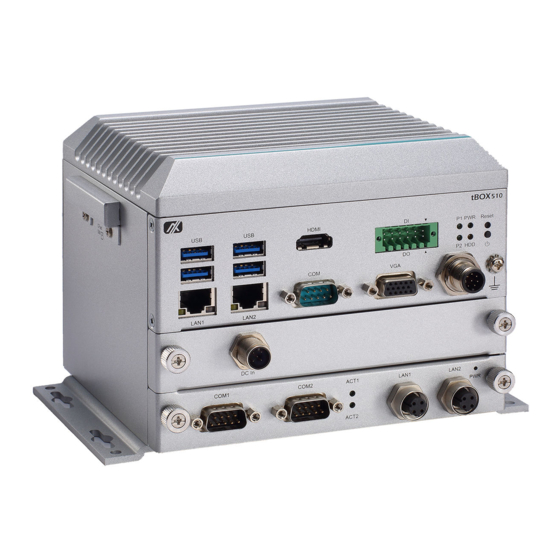
Page 14: I/O Outlets
I/O Outlets The following figures show you the I/O outlets on the front view, top view of the tBOX510-518-FL-24-110MRDC. Packing List The package bundled with your tBOX510-518-FL-24-110MRDC should contain the following items: Standard Optional accessories tBOX510-518-FL-24-110MRDC system unit x 1 ... -
Page 15: Section 2 Hardware Installation
User’s Manual SECTION 2 HARDWARE INSTALLATION The tBOX510-518-FL-24-110MRDC is flexible for your different hardware configurations, such as the hard disk drive and CFast. Chapter 2 will show you how to install the hardware parts. Installing the Memory & Wireless Modules Step 1 Turn off the system. - Page 16 User’s Manual Step 3 Put the thermal pad on the SO-DIMM socket. Then insert the module’s gold finger into the socket and push the module down to complete memory installation. Step 4 Insert the Mini PCIe card into the socket and fasten screws. (Note: the Mini PCIe...
-
Page 17: Installing The Solid-State Disk And Cfast Card
User’s Manual Installing the Solid-State Disk and CFast Card Step 1 Turn off the system. Step 2 Loosen the screws as shown below, and pull out the SSD tray from the system. Be sure to unplug the internal power cable before pulling it out. -
Page 18: Installing The Pim (Plug-In Module)
User’s Manual Installing the PIM (Plug-in Module) Step 1 Turn off the system. Step 2 Loosen all cover screws and remove the cover from the system. Step 3 Install the module as shown below, and fasten the screws firmly to complete the installation. -
Page 19: Installing The Din-Rail Mounting Kit
User’s Manual Installing the DIN-rail Mounting Kit Step 1 Prepare the DIN-rail mount assembly components (screws and the bracket) ready. Step 2 Assemble the brackets to the bottom of the system unit and fasten all screws tight. Introduction... -
Page 20: Installing The Wall Mounting Kit
User’s Manual Installing the Wall Mounting Kit Step 1 Prepare the wall mount assembly components (screws and brackets) ready. Step 2 Assemble the brackets to the bottom of the system unit and fasten all screws tight. Introduction... -
Page 21: Installing The Anti-Vibration Kit
User’s Manual Installing the Anti-vibration Kit Step 1 Prepare the Anti-Vibration Kit components (screws and brackets) ready. Step 2 Assemble the brackets to the bottom of the system unit and fasten screws tight. Introduction... - Page 22 User’s Manual This page is intentionally left blank. Introduction...
-
Page 23: Section 3 Connector
User’s Manual SECTION 3 CONNECTOR Connectors Connectors connect the CPU board with the other parts of the system. Loose or improper connection might cause problems. Make sure all connectors are properly and firmly connected before your turn on the system. -
Page 24: Ethernet Ports
User’s Manual 3.1.2 Ethernet Ports LAN chip: Intel Ethernet Controller I210. The board has dual RJ-45 connectors, supporting 10/100/1000 Base-T with 1.5KV magnetic isolation protection. Pin Description 10/100Base-T 1000Base-T 1 Transmit data+ or bidirectional BI_DA+ 2 Transmit data- or bidirectional... -
Page 25: Wireless
User’s Manual 3.1.5 Wireless 1 x Full size Mini Card socket supports a module with USB, PCIe and SIM Interfaces (Socket 1). 1 x Full size Mini Card socket supports a module with USB and PCIe Interfaces (Socket 2). -
Page 26: Usb
User’s Manual 3.1.6 4 x USB3.0 Pin Signal Pin Signal USB_VCC SSRX2+ USB_Data2- USB_Data2+ 8 SSTX2- SSTX2+ SSRX2- 3.1.7 USB2.0 M12 Connector The USB2.0 connector is an M12 A-code Male 8-Pin connector Signal Signal Shell CHS GND 3.1.8 COM Port ... -
Page 27: Led
User’s Manual 3.1.10 On front panel LED LED Indicator Description PWR/ Green Power on HDD/ Yellow HDD activity P1/ Green Programmable P2/ Green Programmable 3.1.11 Power & Reset Button Power button settings for software must be set up first. - Page 28 User’s Manual This page is intentionally left blank. Connectors...
-
Page 29: Chapter 4 Ami Uefi Bios Utility
User’s Manual CHAPTER 4 AMI UEFI BIOS UTILITY The AMI UEFI BIOS provides users with a built-in setup program to modify basic system configuration. All configured parameters are stored in a flash backup that saves the setup information whenever the power is turned off... -
Page 30: The Main Menu
User’s Manual The Main Menu Once you enter the AMI BIOS Aptio Setup Utility, the Main Menu appears on the screen. In the Main Menu, there are several Setup functions and a couple of Exit options for your selection. Use Select Screen Keys (or Move Keys) to select the setup page you intend to configure and then press <Enter>... -
Page 31: Advanced Features
User’s Manual Advanced Features The Advanced menu also allows users to set configuration of the CPU and other system devices. Users can select any items in the left frame of the screen to go to sub menus: ► Hardware Monitor ►... - Page 32 User’s Manual Hardware Monitor This screen displays the temperatures of CPU and system, as well as system voltages (+3.3V, +12V and +5V ,etc). AMI UEFI BIOS Utility...
- Page 33 User’s Manual F81803 Super IO Configuration Use this screen to select options for the F81803 Super IO Configuration, and change the value of the selected option. A description of the selected item appears on the right side of the screen. For items marked with “”, please press <Enter>...
- Page 34 User’s Manual Serial Port 1 Configuration Use these items to set parameters related to serial port 1. Serial Port 1 Select Mode Use this option to set RS-232/RS-422/RS-485 mode. AMI UEFI BIOS Utility...
- Page 35 User’s Manual CPU Configuration This screen shows the CPU version and its detailed information. AMI UEFI BIOS Utility...
- Page 36 User’s Manual SATA Configuration SATA Mode Selection The AHCI (Advanced Host Controller Interface) mode is how SATA controller(s) operate. Serial ATA Port 0~1 It shows the device installed in connector SATA0~1. AMI UEFI BIOS Utility...
- Page 37 User’s Manual PCH-FW Configuration This screen shows ME Firmware information. AMI UEFI BIOS Utility...
- Page 38 User’s Manual Trusted Computing Select the Security Device Support to enable or disable the TPM function. AMI UEFI BIOS Utility...
- Page 39 BIOS flash utility is a tool for flashing BIOS on setup menu. Follow the steps to flash BIOS. Create a folder and rename it to Axiomtek on the root of USB storage (Ex: X:\Axiomtek). Copy the BIOS file to the Axiomtek folder (Ex: X:\Axiomtek\SBC87518X.005).
- Page 40 User’s Manual AMI UEFI BIOS Utility...
- Page 41 User’s Manual AMI UEFI BIOS Utility...
- Page 42 User’s Manual Device Configuration Device configuration divides into two parts: one part is onboard device; the other is module device. The Module Device Configuration menu would dynamically appear when a module device is plugged into the slot. When no module is plugged in, the screen would only show Onboard Device Configuration.
- Page 43 User’s Manual Onboard DIO Configuration In the onboard DIO configuration, the screen displays DIO information and set I/O. (Please refer below graphics.) AMI UEFI BIOS Utility...
- Page 44 User’s Manual AMI UEFI BIOS Utility...
- Page 45 User’s Manual AMI UEFI BIOS Utility...
- Page 46 User’s Manual Module COM Port Configuration When the module has COM port functions, the module COM configuration menu would show. The default setting for all serial ports is RS232. You can change the setting by selecting the value you want in each COM port type. The system supports RS422 &...
-
Page 47: Chipset Feature
User’s Manual Chipset Feature The Chipset menu allows users to change the advanced chipset settings. Users can select any of the items in the left frame of the screen to go to the sub menus: ► System Agent (SA) Configuration For items marked with “”, please press <Enter>... - Page 48 User’s Manual Memory Configuration This screen shows the system memory information. AMI UEFI BIOS Utility...
-
Page 49: Security
User’s Manual Security The Security menu allows users to set an administrator password and a user password to enhance system security. No password is set in the default setting. (Please refer below graphics.) Administrator Password This item indicates whether an administrator password has been set (installed or uninstalled). -
Page 50: Boot Type
User’s Manual Boot Type The Boot menu allows users to change boot options of the system. Setup Prompt Timeout Use this item to set up number of seconds to wait for setup activation key where 65535(0xFFFF) means indefinite waiting. -
Page 51: Save & Exit
User’s Manual Save & Exit The Save & Exit menu allows users to load system configurations with optimal or fail-safe default values. Save Changes and Exit When users have completed the system configuration changes, select this option to leave Setup and return to Main Menu. - Page 52 User’s Manual Save Changes After completing the system configuration changes, select this option to save changes. Select Save Changes from the Save & Exit menu and press <Enter>. Select Yes to save changes. Discard Changes Select this option to quit Setup without making any permanent changes to the system configurations.
-
Page 53: Appendix Apower Button Setting For Windows
User’s Manual APPENDIX A POWER BUTTON SETTING FOR WINDOWS To define how the power button operates, go to the console of the PC and then follow below figures to complete the setting. Power Button Setting For Windows... - Page 54 User’s Manual Power Button Setting For Windows...
- Page 55 User’s Manual Power Button Setting For Windows...
- Page 56 User’s Manual This page is intentionally left blank. Power Button Setting For Windows...
-
Page 57: Appendix Bdigital I/O
User’s Manual APPENDIX B DIGITAL I/O Digital Input: Ext Power Input Voltage: 30Vdc Max. Digital Input channels: 4, sink/source type Digital Input voltage: 0 to 30VDC Input level for dry contacts: Logic level 0: close Logic level 1: open Input level for wet contacts: Logic level 1: +/-3VDC max. - Page 58 User’s Manual Digital Input Wiring Dry Contact (1): With external power. Dry Contact (2): Without external power. Digital I/O...
- Page 59 User’s Manual Wet Contact (1): Wet Contact (2): Digital Output Wiring DO drive high: x_OUT equal to COM-(up to 200mA) DO drive low: High impedance Digital I/O...
Need help?
Do you have a question about the tBOX510-518-FL-24-110MRDC and is the answer not in the manual?
Questions and answers